


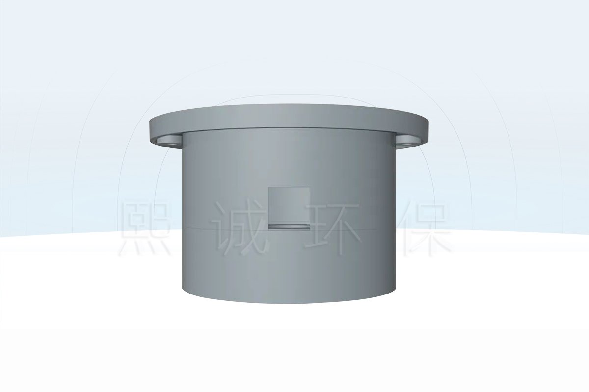
Description
Air Velocity Sensor Overview
This air velocity sensor is designed for low-speed airflow measurement at a fume hood sidewall or another suitable flat-panel location. The selected sensing element converts local air movement into a scaled output for a compatible fume hood monitor, airflow controller or building-control input. Its job is measurement: the receiving equipment displays the value, applies alarm thresholds or uses the signal within a ventilation-control sequence.
Choose This Sensor When
Use the sensor when the project requires a continuous electrical representation of low air velocity rather than a periodic handheld reading. It is a practical candidate for fume hood face-velocity monitoring, laboratory enclosure airflow indication and other low-range ventilation measurements where the installation point, range and output can be defined before ordering.
- The required full-scale range is 0.5, 1, 2 or 5 m/s.
- The monitor or controller accepts a confirmed 0-10 V, 0-5 V, 4-20 mA or compatible communication input.
- A sidewall or flat panel can accommodate the documented sensor body, flange and cable route.
- The project can correlate the installed reading with an accepted measurement at the hood opening.
- The receiving system, alarm logic and airflow-control device are defined separately.
What the Sensor Measures
The device measures air movement at the sensing location, not exhaust volume through an entire duct and not containment performance by itself. In a sidewall-sensing arrangement, the local reading changes with the pressure-driven airflow through the hood and sensor path. During commissioning, that signal is related to the actual average velocity through the open sash area under the approved hood condition.
This distinction matters because two hoods can produce different relationships between a sidewall reading and the velocity across the sash opening. Hood geometry, sensor location, sash position, room disturbances and exhaust condition all influence the installed result. The sensor provides a repeatable electrical measurement input; the project commissioning process establishes how that input represents the hood’s operating target.
What Remains in the Control System
The air velocity transmitter does not include a local touchscreen, alarm annunciator or damper actuator. A monitor may display the measurement and warn the operator. A controller may compare the input with a setpoint and command a damper, Venturi air valve or fan-speed interface. Those devices, their control logic and final acceptance remain separate from the sensor.
Before selection, identify the receiving device and its input type, the desired measuring range, the supply available at the sensor, the panel construction and the cable distance. This prevents a mechanically suitable sensor from arriving with the wrong signal or an output that cannot be scaled by the installed controller.
Key Specifications and Mechanical Dimensions
The published family data covers four low-velocity ranges, several output choices and a compact round-flange housing. Selectable fields are order-specific: the delivered unit should identify the selected range, sensing configuration and output. Values that are ambiguous in the source record have been excluded from the table rather than treated as standard features.
Published Measurement and Electrical Data
| Specification | Published Product-Family Value |
|---|---|
| Product function | Low-range air velocity sensor/transmitter |
| Selectable ranges | 0-0.5, 0-1, 0-2 or 0-5 m/s |
| Accuracy | 0.05 m/s + 3% of measured value |
| Resolution | 0.02 m/s |
| Supply | 12-36 VDC; 24 VDC is shown in the terminal reference |
| Supply allowance | Source specifies at least 1.5 W available |
| Analog output options | 0-10 V, 0-5 V or 4-20 mA |
| Communication connection | POW+, GND, A and B terminal arrangement; protocol to be confirmed for the ordered version |
| Operating environment | -5 to +70 deg C; 0-95% RH |
| Housing | Flame-retardant ABS; off-white/gray finish |
| Mounting | Sidewall or flat-panel insertion mounting |
The range is not a software label to be chosen after commissioning unless that capability is explicitly confirmed for the supplied version. Match the full-scale value to the expected operating window and to the receiving input scaling. An unnecessarily broad range reduces the useful share of the output assigned to normal hood operation, while a range below the possible maximum can saturate before the highest operating condition is reached.
Housing, Flange and Panel Opening
The dimension drawing shows a 70 mm circular outside envelope, a 53 mm body reference, a 39 mm depth and a 5 mm flange reference. A 60 mm feature is also identified on the front view. The installation drawing provides 55 mm and 60 mm opening references together with 2.5 mm self-tapping and 3.5 mm standard screw options. Confirm the final mounting drawing supplied with the selected version before the hood panel is drilled.
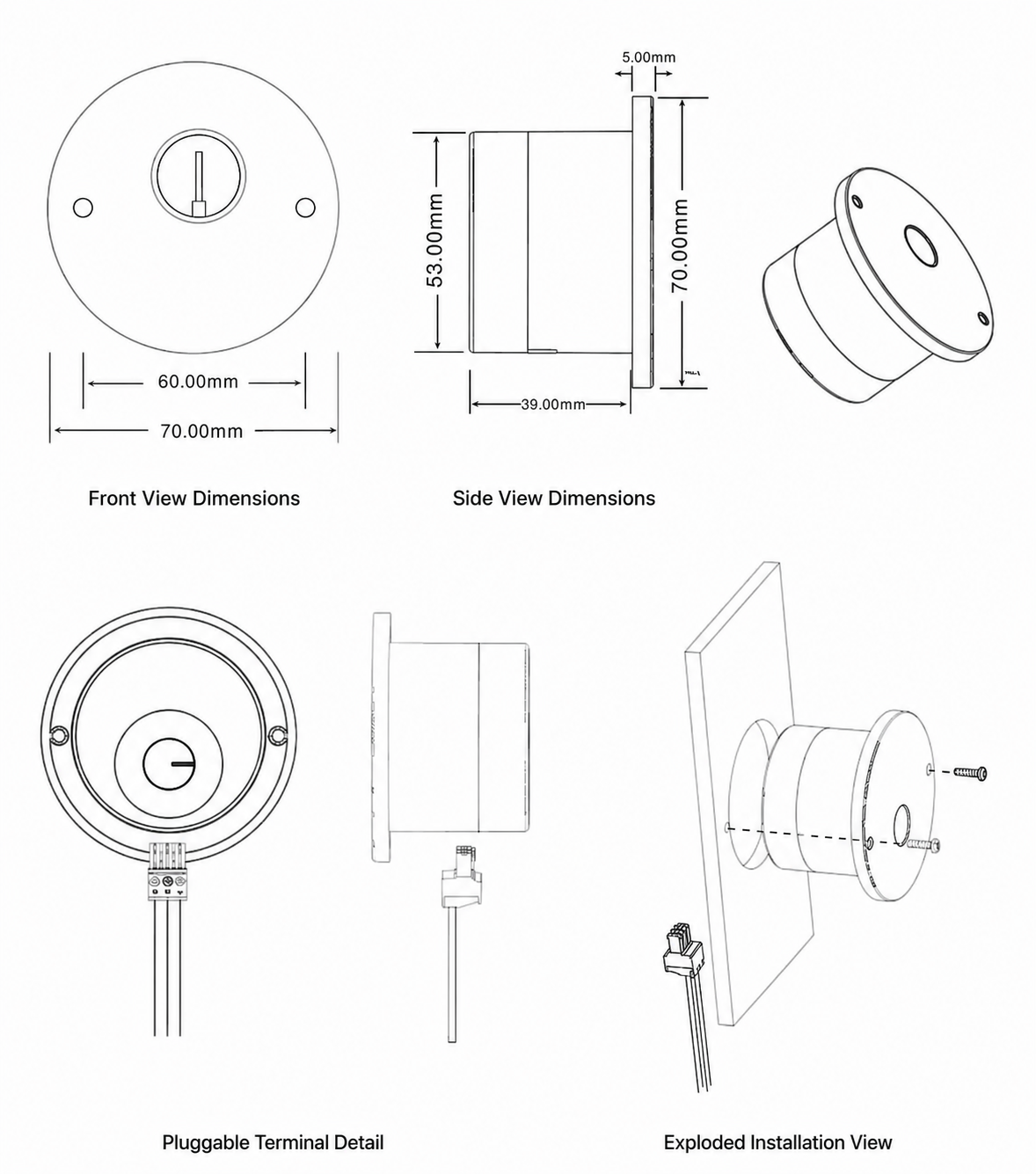
Allow rear clearance for the inserted body, removable terminal connection and cable bend. The front flange must sit flat against the mounting surface so that the body is not twisted or loaded by an uneven panel. For retrofit work, record the existing opening, panel thickness, available rear space and cable direction instead of selecting the replacement from front diameter alone.
Face Velocity Measurement and Signal Meaning
The product family is described with thermal-dissipation or Pitot-based sensing configurations. These are alternative measurement approaches, not a claim that every supplied sensor contains both. The quotation and delivered documentation should identify which configuration applies, because the sensing path, environmental suitability and commissioning checks depend on the selected version.
Thermal-Dissipation and Pitot-Based Configurations
A thermal-dissipation sensor relates air movement to heat transfer from a sensing element. As local velocity changes, the electronics convert the corresponding thermal response into a scaled measurement signal. The source describes digital calibration, linearization and temperature compensation within the transmitter. These functions support low-range measurement, but they do not remove the need to verify the installed reading against the real hood condition.
A Pitot-based configuration derives a velocity-related signal from pressure created by moving air. Its installation must preserve the intended pressure path and avoid blocked or poorly located openings. Because the first-source record presents the two principles as family alternatives, the project should not substitute one for the other without confirming the ordered construction, connection and calibration data.
From Local Air Movement to a Scaled Output
The measurement chain is straightforward: air moves through or across the installed sensing path; the sensing element responds; the transmitter linearizes the result; and the selected output represents velocity over the ordered range. For a 0-10 V version, for example, the receiving controller must use the same zero and full-scale values as the sensor. A 4-20 mA version requires the matching current input and loop arrangement. A communication version requires confirmation of the actual protocol, addressing and data definition.
The signal is therefore meaningful only when four fields agree: sensor range, output type, receiving-input type and controller scaling. A stable voltage or current does not prove that those fields match. During setup, check the zero or low-flow response, apply a known operating condition and compare the controller display with the expected engineering value.
Why Site Correlation Is Required
Sidewall face-velocity sensing is an indirect representation of average velocity through the sash opening. The sensor observes the airflow at its own path, while the commissioning instrument samples the hood opening. Their numerical values are not assumed to be identical; the control or monitoring system uses an established relationship between them.
That relationship should be set under a documented sash opening, exhaust condition and room condition. After correlation, verify more than one operating point when the hood is used over a variable range. If the sensor is relocated, the hood geometry changes or the exhaust system is modified, repeat the relevant verification. The sensor output can then serve as a continuous operating input, while periodic hood performance checks remain part of the facility’s approved procedure.
Output Options, Terminals and Wiring
Output selection determines how the measured velocity reaches the fume hood monitor or airflow controller. The published product family includes 0-10 V, 0-5 V and 4-20 mA analog variants, plus a version illustrated with A/B communication terminals. Confirm the output at quotation stage; the same housing does not mean that every signal type is present on every unit.
Analog Voltage and Current Outputs
The analog terminal arrangement uses POW+ for the positive DC supply, GND for the common return and OUT for the velocity signal. A voltage-output version requires a compatible high-impedance analog input and a shared signal reference. A 4-20 mA version requires the current-input arrangement specified by the receiving device. The controller scaling must use the selected sensor range so that its displayed engineering value corresponds to the transmitter output.
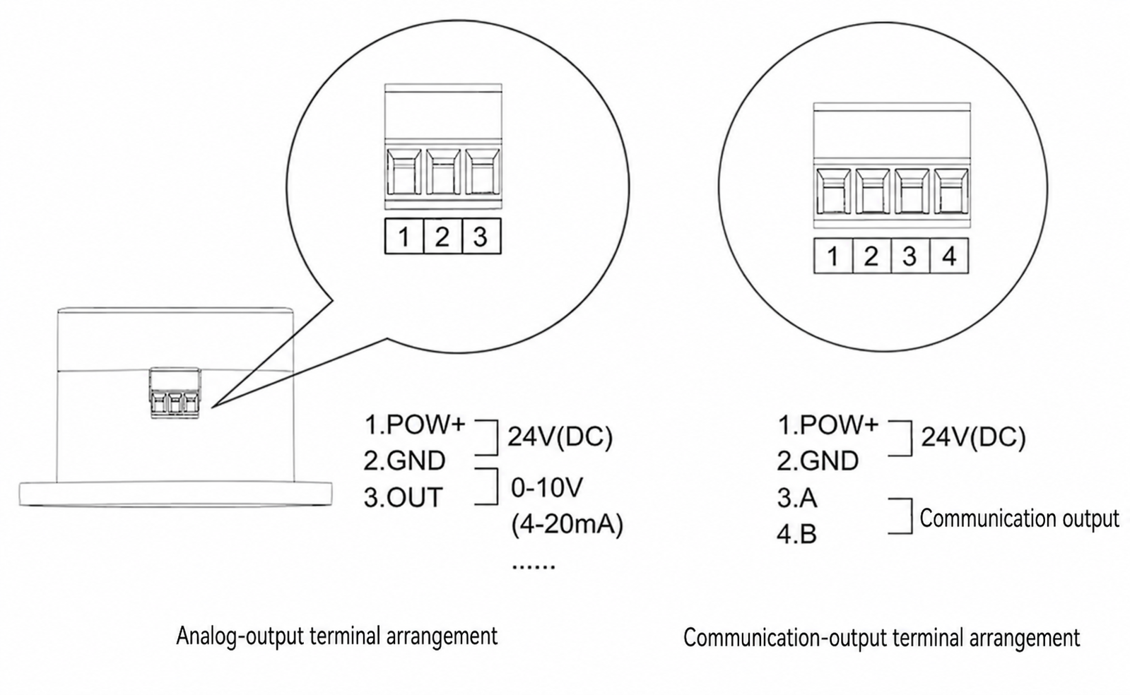
For example, a controller configured for 0-5 m/s must not be paired with a 0-1 m/s sensor and left with the 0-5 m/s scaling. The electrical signal may still vary normally, but the displayed velocity will be wrong. Record the ordered range and signal beside the hood tag, and verify the controller’s zero and full-scale values during commissioning.
Communication Terminal Arrangement
The communication drawing shows POW+, GND, A and B. It establishes the terminal roles but does not identify a protocol in the available product record. Confirm the communication protocol, address method, baud rate, parity and register definition for the delivered version before it is connected to a controller or supervisory network. Do not treat A/B labels alone as proof of Modbus compatibility.
Keep communication polarity consistent through the network and follow the project requirements for topology, shielding, grounding and termination. Where the sensor connects first to a dedicated hood controller, the BMS should normally obtain the engineered value from that controller rather than creating an undocumented parallel connection to the sensor.
Cable-Distance References and Receiving Devices
The source lists reference distances of 70 m for 0.5 mm2 BVVR conductors, 200 m for 1.0 mm2 and 300 m for 1.5 mm2. These figures help estimate cable sizing, but final allowable distance also depends on the selected output, voltage drop, loop resistance, electrical interference, cable routing and receiving-input requirements. Confirm the cable schedule for the actual signal rather than applying the longest figure automatically.

Route sensor wiring away from moving sash parts, mains conductors and high-noise motor or variable-frequency-drive cables. Label the sensor end and controller end with the hood tag, range and signal type. Before energizing the circuit, check polarity, supply voltage and the receiving input. After energizing, compare the raw signal and displayed engineering value at a known airflow condition.
Installation and Functional Verification
Mechanical location is part of the measurement system. A correctly wired airflow velocity sensor can still produce an unrepresentative signal if the opening is obstructed, the flange is distorted or the sensing path sits in a local eddy. Coordinate the location with the hood manufacturer and controls designer before the sidewall is machined.
Sidewall or Flat-Panel Mounting
The documented arrangement inserts the rear body through a central opening and fixes the front flange parallel to the sidewall or flat mounting surface. The drawing shows 55 mm and 60 mm opening references and alternative screw details. Use the drawing issued for the delivered sensor to finalize the opening and fasteners; panel material and thickness can change the appropriate hardware.
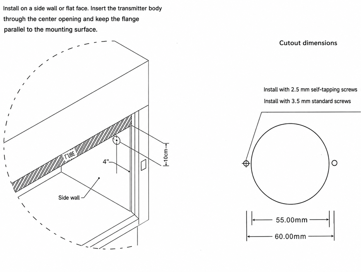
Check the rear space before drilling. The body, removable terminal and cable bend must clear the hood liner, sash guides, counterweight path and service panels. Keep the cable accessible for testing or replacement. Seal or finish the panel penetration according to the hood construction and project requirements without blocking the intended sensing path.
Avoiding Disturbed or Unrepresentative Airflow
Choose a position that reflects the intended sidewall-sensing arrangement and remains clear of direct drafts from doors, supply diffusers and frequently moved equipment. The sensor should not interfere with normal hood work or the sash mechanism. Avoid locations where a shelf, internal baffle change or cable bundle can obstruct the opening after handover.
A sidewall sensor observes airflow driven by the hood pressure relationship. It should not be installed as though it were a duct probe intended to calculate total volume. If the project needs duct velocity or airflow volume, review the required probe location, duct area and calculation method separately. For a fume hood, the commissioning target remains the accepted face-velocity condition at the sash opening.
Commissioning Against the Hood Opening
First verify supply, output type, range and controller scaling with the exhaust system in a known state. Then measure the hood opening using the project’s accepted instrument and traverse method at the documented sash position. Compare that result with the sensor signal or controller display and establish the required correlation in the receiving system.
Test the normal operating point and other relevant sash or exhaust conditions rather than accepting a single convenient reading. Confirm that the signal changes in the expected direction, remains stable and returns when the condition is repeated. Where alarms or closed-loop control use the signal, test the threshold and controlled response through the complete system.
Record the sensor range, output, location, controller scaling, reference instrument and accepted results for the hood tag. Repeat the relevant verification after sensor replacement, relocation, major hood modification or a change that affects the exhaust and room-air relationship. No universal recalibration interval is stated for this product; follow the facility’s approved inspection and certification program.
Applications, System Fit and Product Selection
The product is suitable where low air velocity must be converted into a continuous electrical input. Its strongest page-specific fit is fume hood face-velocity measurement, but the available ranges can also support compatible laboratory enclosure and ventilation measurements. Selection should begin with the physical variable and receiving system, not with the housing appearance.
Fume Hood Face Velocity Measurement
For a fume hood, the sensor is normally installed at a sidewall or approved panel location that responds to the hood’s pressure-driven airflow. A monitor can use the input to show face velocity and generate local alarms. A fume hood face velocity controller can use the signal as part of a closed-loop sequence that commands an exhaust damper, Venturi air valve or fan interface. In both cases, field correlation links the sensor signal to the accepted measurement at the sash opening.
The sensor can support a constant-volume hood where continuous monitoring is required, or a variable-volume hood where the control strategy uses face-velocity feedback. It does not determine the target velocity or prove containment. Those requirements come from the project basis, hood design, risk assessment and commissioning procedure.
Sensor Versus Monitor and Controller
Select this page when the required item is the sensing/transmitting device. Select the fume hood airflow monitor when operators need a local display, alarms and approved commands. A controller is required when the system must compare the measurement with a setpoint and regulate exhaust equipment. One project may use all three products, but they perform different functions.
The broader Fume Hood System Accessories category includes related operator panels, sensors and electrical accessories. Keep each device on the controls schedule with its own supply, signal, connection and responsibility so that a sensor is not ordered as a substitute for the display or controller.
Choosing Range and Output
Choose the smallest range that includes the expected maximum and any commissioning or emergency condition the sensor must represent. The 0-0.5 and 0-1 m/s options devote more of the signal span to low-speed measurement; the 0-2 and 0-5 m/s options accommodate higher conditions. The final choice should follow the actual application and input scaling rather than an assumption that a broader range is always better.
Use 0-10 V or 0-5 V when the receiving device is designed for the matching voltage input and the cable arrangement is appropriate. Use 4-20 mA when the project and controller require a current input. Choose the communication version only after the protocol and integration details have been confirmed. Specify the supply separately from the output so that a 24 VDC terminal reference is not mistaken for the only accepted supply within the published 12-36 VDC range.
Information Required for a Quotation
For each sensor tag, provide the application, required velocity range, preferred output, available DC supply, receiving monitor or controller, hood and sash arrangement, proposed mounting location, panel material and thickness, opening drawing, cable length and route, quantity and destination. Include the control schematic and input specification when available.
The quotation should identify the proposed sensing configuration, selected range and output, terminal arrangement, included mounting components and applicable published performance values. It should also state any information that must be confirmed before manufacture. This tag-level schedule is important for custom laboratory projects because visually similar sensors can be configured for different ranges and receiving interfaces.
Frequently Asked Questions
Is this sensor the same as a fume hood airflow monitor?
No. The air velocity sensor produces a measurement signal. A fume hood airflow monitor receives and displays the value, applies the configured alarm logic and may provide operator controls. A controller is additionally required when the measurement must regulate exhaust airflow.
Which measurement ranges are available?
The published product family offers 0-0.5, 0-1, 0-2 and 0-5 m/s ranges. Select the range against the expected operating and maximum conditions, then use the same full-scale value in the receiving monitor or controller.
Can the sensor provide both voltage and 4-20 mA outputs?
The source lists 0-10 V, 0-5 V and 4-20 mA as output options. Treat them as selectable variants unless the quotation explicitly confirms multiple outputs on one unit. The sensor output and controller input must match.
Does the A/B terminal version use Modbus?
The available drawing confirms POW+, GND, A and B terminals but does not identify the protocol. Confirm the protocol, addressing and data definition for the delivered communication version before integration.
Can the sidewall reading be used as face velocity without commissioning?
No. Sidewall sensing measures airflow at the sensor path, while face velocity is evaluated across the sash opening. The installed system must establish and verify the relationship under the documented hood condition before the value is used for alarms or control.
How far can the sensor be wired from the controller?
The source provides reference distances of 70 m with 0.5 mm2 conductors, 200 m with 1.0 mm2 and 300 m with 1.5 mm2. Final distance depends on the output type, voltage drop, loop resistance, interference, routing and receiving input, so confirm the project cable schedule.
What information is needed to select the correct version?
Provide the velocity range, output, supply, receiving device, hood arrangement, mounting panel, cable route and length, quantity and destination. A hood-front or sidewall drawing and controls schematic help confirm the opening, clearance and electrical interface.
Contact the Xicheng Engineering Team Today
Send the hood drawing, expected velocity range, required output, available DC supply, receiving monitor or controller, mounting location, panel construction and cable schedule. XICHENG will review the sensor configuration, mechanical fit and signal interface and provide a project-specific proposal and quotation.
Shenzhen Office: No. 34 Zhenxing Road (Shengtaian Heavy Industrial Park B), Loucun, Guangming New Dist, Shenzhen, Guangdong, China
WhatsApp: +86 18126478161
Engineering Mailbox: fanalax34@gmail.com