


Key Specifications and First Selection
An ESD lab bench should be selected as an electrostatic discharge control system at the point of work. The work surface is important, but it is only one part of the path. A complete configuration identifies the selected surface material, connection from the surface to the common point ground, grounding lead, frame bonding where specified, personnel-grounding interface, accessories and the method used to test the installed workstation. A product cannot become an ESD workstation simply because it is called anti-static or because a mat is placed on an ordinary table.
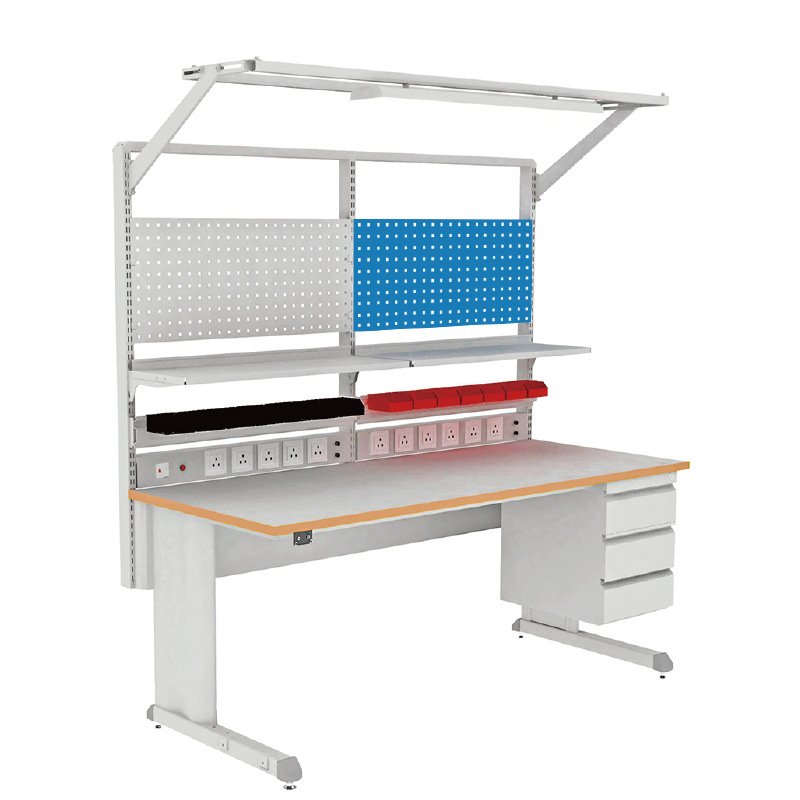
The high-intent term electrostatic discharge workstation is used for laboratories and electronics areas that need to protect sensitive devices during assembly, test, inspection or repair. The selected frame can be fixed height, manually adjustable, crank-adjustable or electrically adjustable. Those choices change the load path, working-height range, cable movement, accessory arrangement and test access. Do not combine a fixed-frame load value with an electric-lift rating or assume that all surface and frame components are conductive.
| First selection field | Decision required | Why it changes the workstation | Information to confirm before release |
|---|---|---|---|
| ESD control path | Work surface, common point ground, cord, plug and personnel connection | Determines how charge is directed and how continuity is checked | Resistance targets, test method, test voltage and connection responsibilities |
| Frame and height | Fixed, manual, crank or electric structure | Changes height, load, power, cable movement and stability | Work position, adjustment frequency, load and selected mechanism |
| Worktop and equipment | Surface type, thickness, edge, local device supports and tools | Affects ESD behavior, chemical use, support and cleanability | Device sensitivity, equipment footprint, soldering or chemical exposure |
| Accessories | Shelves, lights, power rail, bins, drawers and monitor mount | Each accessory adds load and may require its own ESD assessment | Attachment load, electrical scope, grounding status and clearances |
Separate surface performance from the entire system
Surface resistance, point-to-ground resistance, frame bonding and personnel grounding are not interchangeable measurements. A worktop can have an appropriate surface property while the grounding lead is absent or disconnected. A metal frame can be present without forming the intended controlled path. The final specification should identify what is being measured, from where to where, with what instrument and at what stage of installation. This prevents an incomplete workstation from being described as a complete ESD control area.
Reference dimensions and mechanisms
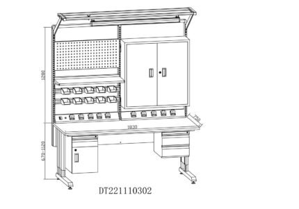
Published ESD workbench families show several separate arrangements: 1073, 1500 and 1800 mm widths at 800 mm depth with 700-1100 mm manual or electric height in one family; a 1250 x 750 mm electric worktop with 610-1200 mm height, 250 kg distributed load and 38 mm/s movement in another; and 1200, 1600 or 2000 mm by 800 mm powered stations at 690-1180 mm with a 300 kg stated load in a third. These references guide initial selection only. A final bench must use one compatible mechanism, frame, worktop, grounding system and load definition.
Start with the device and task
Provide the device sensitivity and handling process, whether work involves assembly, PCB inspection, rework, measurement or repair, and whether the operator is seated or standing. Record soldering, flux, cleaning chemicals, optical instruments, power supplies, computer equipment, tool storage and any controlled-area requirements. This lets the finished ESD laboratory workbench support the actual task without treating unrelated accessories as automatically static-controlled.
ESD System Scope and Grounding Path
An ESD workstation is a controlled path for charge management, not a single material claim. The project should define the sensitive devices, required work-surface behavior, common point ground, personnel grounding equipment and the tests needed after the workstation is assembled. IEC 61340-5-1 and ANSI/ESD S20.20 are often referenced within facility ESD programs, but a furniture page should not claim organization-wide conformity without the required control plan, records and site procedures.
The work-surface path
The selected ESD work surface may be static-dissipative or conductive according to its material and intended use. Its surface resistance should be defined separately from the resistance between the surface and the common point ground. Edge banding, seams, cut-outs, conductive layers, mats and attachment hardware can affect the path. Record the selected material, thickness, edge treatment, grounding point location and test access before equipment is placed on the surface.
Common point ground and personnel interfaces
The common point ground should be specified with the required leads, connectors and any safety resistance. Personnel grounding may use wrist-strap connection points, footwear and flooring practices, or other facility-defined methods. These are related parts of the broader workstation but should be listed individually. A wrist-strap socket does not prove that the worktop, frame, operator and building grounding system are connected correctly; each path needs the specified installation and check method.
Frame bonding and non-ESD parts
Powder-coated steel, aluminum extrusion, painted components, plastic bins, task lights, control panels, display arms and drawers can have different electrical behavior. Do not use the words conductive or dissipative for an entire workstation unless the released configuration identifies the relevant components and test points. Where the frame is intended to be bonded, the connection method and accessible bonding points should be documented. Where an accessory has no stated ESD property, describe it as a selected accessory rather than an ESD component.
Installation and periodic checks
Check the surface, common point ground, cord, connectors and personnel interfaces after installation and at the interval required by the site’s control program. Any new worktop, cut-out, power strip, upper shelf, drawer, mat or cable change can alter the original arrangement. Keep the selected test method, instrument settings, measurement points, acceptance criteria, tester responsibility and retest interval with the released workstation documentation.
Frames, Work Surfaces and Load Conditions
The ESD control fields do not remove the ordinary mechanical requirements of a laboratory workbench. The selected frame must support the worktop, instruments, accessories and operator use condition, while the work surface must retain its specified electrical role at seams, edges and cut-outs. Steel frames, aluminum-profile systems and lifting bases are all possible directions, but their dimensions, load ratings, attachment methods and grounding details remain configuration-specific.
Reference configuration families
| Configuration family | Published planning direction | Mechanical distinction | ESD boundary |
|---|---|---|---|
| Manual or electric bench family | 1073/1500/1800 mm width, 800 mm depth, 700-1100 mm height and 300 kg stated load in one family | Manual, electric and crank variants have different operating loads and movement behavior | Worktop, ground point and test fields must be selected for the final version |
| Electric workstation reference | 1250 x 750 mm top, 610-1200 mm height, 250 kg distributed load and 38 mm/s in another family | Includes an electric lift and separate stability structure | A conductive worktop does not make the control panel or every mechanism conductive |
| Aluminum-profile accessory station | 1200-2280 mm lengths, 600/750/900 mm depths and up to 500 kg stated reference in one family | Uprights, shelving and light support are selected with the profile system | Each attachment needs an identified material and grounding relationship |
| Steel-frame workstation family | Single-sided 1500/1800/2100 x 750 x 800 mm examples | Frame and optional accessories can form an electronics work area | Conflicting published family load values require a selected final schedule |
Work surface selection
An ESD laminate, volume-conductive top, dissipative surface material or controlled mat system should be selected from the device sensitivity, electrical targets, mechanical use, chemical exposure, heat and cleaning method. The table surface needs enough support for the equipment feet and enough edge integrity around cut-outs, fixtures and mounted instruments. A surface used for soldering, flux removal or solvent wiping may need a different chemical review from one used only for dry electronics assembly.
Distributed, local and accessory loads
Published bench capacities often describe an evenly distributed condition. A large power supply, microscope, test fixture, soldering extraction arm, display mount, upper shelf or drawer bank can create a local or offset load that is not represented by that value. Define the total worktop mass, equipment footprints, feet locations, center of gravity, shelf contents, drawer load and any force applied during adjustment. If the bench has casters or lift movement, their conditions need separate approval from the stationary load.
Frame material and equipment access
Steel frames can provide a stable work surface and support for standard storage. Aluminum-profile frames can provide repeatable slots for accessories and task equipment. Neither material choice alone guarantees ESD continuity. The final arrangement should show which components are structural, which are electrical-control components, and which are only accessories. Leave access to grounding points, test locations, power connections, equipment rear panels and service routes after shelves and storage are installed.
Chemical and thermal boundaries
Electronic work can introduce fluxes, solvents, cleaners, hot tools or battery processes. Define the actual substances, temperature and contact method before selecting the worktop and edge treatment. An ESD surface should not be assumed to tolerate every chemical or hot tool. Where the task requires a different chemical work surface, consider a separate protected process area instead of compromising the selected static-control arrangement.
Height, Accessories and Ongoing Control
The workbench height should be selected for the device-handling task, operator posture and equipment view line. A fixed-height frame may be appropriate for a repeatable process. A manually adjusted, crank-operated or electrically adjusted frame can support different users and tasks, but it introduces separate movement, power, cable and load considerations. Height adjustment does not remove the need for an accessible ESD connection and a stable equipment layout at every selected position.
Fixed, manual and electric arrangements
Fixed benches are simple to plan where the operator posture and equipment location are stable. Manual adjustment can suit occasional setup changes, provided the tool, crank or locking mechanism remains accessible and the equipment condition is defined. Electric lift bases are useful for more frequent changes but need the selected power supply, controller, cable slack, movement clearance, duty condition and load during travel. A height range stated for one lift family must not be applied to a different frame or surface configuration.
Accessory system planning
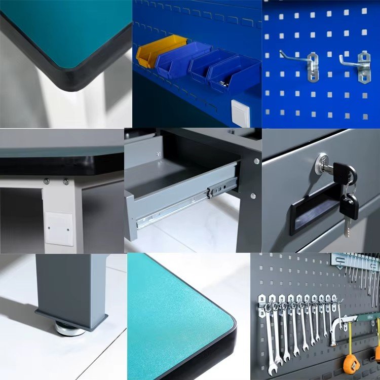
Shelves, task lights, power rails, tool panels, parts bins, monitor arms, drawers and suspended cabinets can improve the work sequence but should be treated as individual technical items. Their attachment loads, working height, electrical supply, cable paths and ESD behavior may differ. A power rail may be electrically powered without providing a static-control ground. A plastic parts bin may be useful for storage without being a controlled dissipative component. Keep each accessory on the released configuration list.
Cables, service routes and motion
Route power, data, test leads, grounding cords and instrument cables so they do not pull on the common point ground, obstruct adjustment, create snag points or block access to test locations. An electric height-adjustable configuration needs a full-travel review with all cables and hoses connected. A manual bench still needs enough service slack for maintenance and equipment repositioning. Do not hide a grounding point behind a fixed cabinet or a permanently loaded drawer.
Worktop openings and shared positions
Cable grommets, outlet boxes, test-lead openings, microscope mounts and service cut-outs should be located before the work surface and grounding path are finalized. An opening can interrupt a conductive layer, remove usable ESD surface area or force a grounding cord into an inaccessible position. In a shared position, give each operator a defined work zone, personnel-grounding interface and reachable test point rather than asking several users to work across one uncontrolled surface. Record the position of each opening, mounted device, ground point and accessory upright on the released drawing.
Maintenance and retest triggers
Review the work surface, grounding components, accessory attachments, cable condition, frame fasteners, height mechanism and equipment layout at the site’s defined interval. Retest the affected ESD path after replacing a top, adding a mat, moving a ground point, changing a power rail, adding an upper module, modifying an opening or relocating the station. A visible surface can remain clean and undamaged while a grounding path has changed; the documented test process detects that difference.
Applications, EPA Fit and Product Boundary
An ESD laboratory workbench can support electronics assembly, PCB inspection, test, repair, calibration and other device-handling tasks where the work area forms part of a wider electrostatic discharge control program. The useful configuration begins with the sensitive item and process. A large test fixture needs a different support and cable arrangement from small component assembly; soldering, optical inspection, cleaning or battery handling can each introduce different worktop, extraction, lighting or chemical boundaries. Where the layout is a conventional fixed line without ESD requirements, a laboratory wall bench or laboratory island bench provides the more appropriate starting point for the furniture plan.
Electronics assembly and PCB work
Electronics assembly often needs a stable surface, defined component placement, task lighting, tool storage and accessible power or data connections. The selected ESD path should remain accessible while the board, fixture, mat, wrist strap, test lead and tools are in normal use. Upper shelves and parts bins should not turn a grounded work surface into an inaccessible collection area. When a process uses solder, flux or solvent, verify that the selected surface and cleaning method suit those materials.
Inspection, repair and laboratory testing
Inspection and repair tasks may require a microscope, display, power supply, measurement instrument or articulated support. Each can create local load, cable and visibility constraints. The workstation drawing should identify its footprint, maintenance access and any attachment to the frame. A precision instrument with vibration limits may be better served by a dedicated laboratory instrument table or anti-vibration balance table instead of using an ordinary ESD workbench as its support.
Controlled areas and combined requirements
Some electronics operations combine static control with cleanliness or process-specific material requirements. In those cases the ESD path, cleanability and environmental requirements should be reviewed independently. A related stainless steel laboratory bench may define an open stainless steel furniture configuration, but it does not replace the complete electrical-control fields of an ESD workbench. Similarly, an ESD label does not establish particle suitability or chemical compatibility.
What this product is not
This page is not for ESD mats, wrist straps, ionizers, continuous monitors, ESD chairs, ESD carts or a facility-wide ESD program. Those items can form part of a project, but they are not interchangeable with the principal workstation. The page also does not describe a clean bench, fume hood, biosafety cabinet or generic office table. The released product is a selected laboratory workbench with a documented static-control arrangement.
Installation, Test Planning and RFQ
The released installation should show the workbench position, worktop, frame, common point ground, grounding lead, power, data, equipment, accessories and required test access. Before equipment is installed, confirm that the floor, building grounding interface, service connections and work area layout support the selected configuration. A completed bench should retain an accessible way to inspect and test the intended static-control path.
Installation sequence
Assemble and level the selected frame, install the work surface, then fit the grounding point and leads according to the project electrical plan. Add uprights, shelves, lights, power rails, drawers and storage only after their attachment and routing are clear. Place equipment in the documented order and check local support, cable travel, operator reach and access to the ground point. For a height-adjustable model, perform the required movement check with the planned equipment and cable condition.
Test planning
The test plan should identify the surface-resistance measurement, point-to-ground measurement, grounding-continuity check and personnel-grounding interfaces that apply to the selected program. Define test equipment, settings, contact positions, environmental conditions, acceptance limits, responsible person, records and retest timing before handover. Different tests answer different questions; one successful resistance reading should not be used as proof of an entire workplace control program.
Test access after normal setup
Plan the test locations after the normal equipment, shelves, bins and operator tools are installed, not only on an empty worktop. The common point ground, surface test area and personnel connection should remain reachable without dismantling the work station or disconnecting active equipment. If a task uses a removable mat, portable fixture or temporary instrument, define whether it is part of the routine test condition and where it is placed during a check. This prevents a documented test plan from becoming impractical during normal production or laboratory work.
| Planning item | Required project input | Decision produced | Check before release |
|---|---|---|---|
| Device and task | Device sensitivity, process, operator posture, instruments and chemicals | Surface, worktop, height and accessory arrangement | Work area supports the real task without blocking test access |
| ESD path | Surface property, ground point, cord, plug, bonding and personnel interfaces | Grounding configuration and measurement plan | Each selected path is accessible and included in the test method |
| Frame and loads | Dimensions, equipment mass, local supports, shelves, drawers and mobility | Frame, worktop support and height mechanism | Distributed, local, accessory and moving loads are distinct |
| Utilities and delivery | Power, data, lighting, cable route, installation location and destination | Installation scope and service routing | Cables, grounding leads and accessories remain protected and reachable |
Information for a project-ready quotation
Provide the device and work process; required bench width, depth and height; fixed, manual or electric adjustment; selected worktop; intended electrical behavior and test method; ground point and building connection details; equipment schedule; local and total loads; accessories; power and data; chemicals or hot-tool use; cleaning method; quantity; installation conditions; and destination. The resulting proposal can define the ESD lab bench as a complete configuration with its mechanical and electrical boundaries clearly stated.
Frequently Asked Questions
Is an anti-static mat on a standard table the same as an ESD workstation?
No. A mat can be one selected component, but an ESD workstation also needs a defined work surface, grounding path, common point ground, personnel connection where required, test method and controlled accessory arrangement. The full path and verification method should be specified for the actual task.
Should the frame be steel or aluminum profile?
Choose the frame from required load, accessories, workspace layout and service routing. Steel and aluminum can each support selected workstation arrangements, but neither choice automatically establishes a static-control path. The work surface, bonding and ground points must be defined separately.
Can the bench be height-adjustable?
Yes, a selected manual, crank or electric configuration can be considered. The released design must define its working-height range, moving load, controls, cables, stability and access to the grounding components. Do not apply a range or load from an unrelated lift mechanism.
Are all accessories ESD controlled?
No. Shelves, lights, power rails, drawers, bins and monitor arms may be structural or electrical accessories without being static-control components. Each item should be specified by material, attachment, load, electrical scope and grounding relationship.
Does this product make an entire facility ESD compliant?
No. Facility-wide control also depends on procedures, flooring, personnel practices, instruments, verification and records. The selected workstation is one controlled point of work within that broader program.
Contact the Xicheng Engineering Team Today
Send the device-handling process, required worktop, grounding and test method, equipment schedule, target bench dimensions, height arrangement, accessories and installation conditions. The engineering proposal can define a suitable ESD laboratory workstation configuration and pricing within 24 hours.
Manufacturing Head Office: No. 34 Zhenxing Road (Shengtaian Heavy Industrial Park B), Loucun, Guangming New Dist, Shenzhen, Guangdong, China
Direct Hotline / WhatsApp: +86 18126478161
Engineering Mailbox: fanalax@gmail.com