


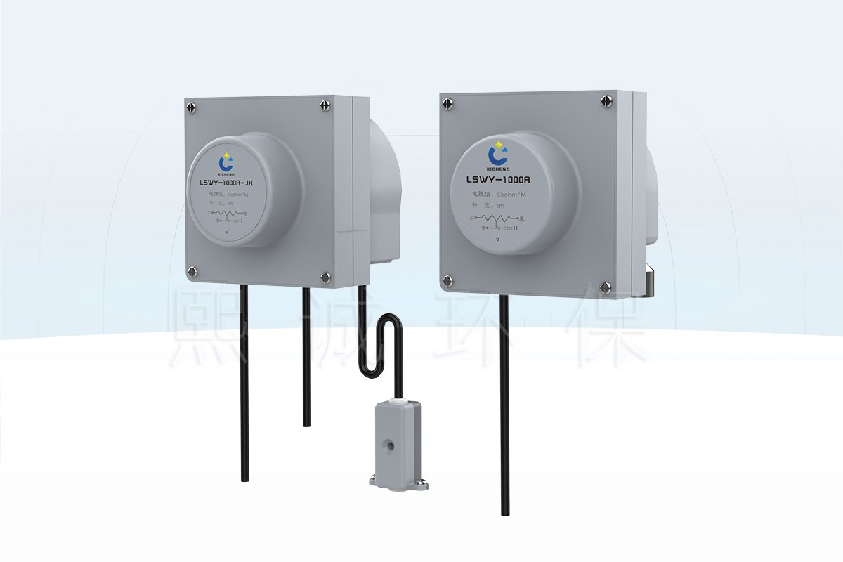
String Potentiometer for Fume Hood Sash Position
This string potentiometer measures the linear position of a vertical fume hood sash. A flexible cable attaches to the sash or a mechanically equivalent moving point. As the sash rises and falls, the cable extends from or returns to a spring-loaded reel, rotating a precision potentiometer and changing the resistance signal received by the controller.
Choose This Sensor When
The draw-wire structure is a practical choice when a protected, nearly straight cable path can follow the complete sash movement. It avoids adding a separate coupling to a pulley shaft and makes the measured travel easy to relate to the physical sash opening. The 1,000 mm range suits vertical travel that remains inside the usable cable stroke with margin at both ends.
- The sash travels no more than the usable portion of the 1,000 mm cable range.
- The sensor can be mounted so the cable remains in line with the outlet.
- The controller accepts the selected 5 kOhm or 10 kOhm potentiometer input.
- The cable path is protected from sharp edges, moving counterweights and work-area interference.
- The automatic-sash or VAV controller can calibrate closed and open positions.
Key Product Data
The sensor uses a flame-retardant ABS enclosure, a spring-return reel, a high-precision sliding resistor and a slip ring for signal transfer. Maximum cable travel is 1,000 mm, with measurement error within 2%. The product family supports 5 kOhm and 0-10 kOhm resistance configurations, selected to match the controller input rather than combined as two simultaneous outputs.
What the Sensor Does Not Control
The fume hood sash position sensor reports travel; it does not drive the sash or decide when movement is allowed. The automatic sash controller uses the position feedback together with manual commands, occupancy input and obstruction protection. In a VAV system, a separate airflow controller can map sash opening to an exhaust-airflow command.
The product image also shows a JK configuration with a separate anti-pinch signal path. That signal remains a distinct controller input. The resistance output reports position and must not be treated as proof that the descending sash path is clear.
Key Specifications and Sensor Configurations
Match the travel and resistance configuration before ordering. The 5 kOhm and 10 kOhm references represent different potentiometer versions within the product family. The controller input, cable route and optional anti-pinch connection determine the correct configuration.
| Specification | Product Data |
|---|---|
| Sensor type | Spring-return draw-wire potentiometer |
| Measured variable | Linear fume hood sash travel |
| Maximum cable travel | 1,000 mm |
| Resistance configurations | 5 kOhm or 0-10 kOhm, selected for the controller input |
| Measurement error | Within 2% |
| Enclosure | Flame-retardant ABS |
| Signal transfer | Precision slip ring |
| Return mechanism | Spring-loaded cable reel |
| Maximum cable speed | 1 m/s |
| Maximum instantaneous acceleration | 2 m/s2 |
| Mounting | Four side fixing holes; direct or bracket mounting |
| Optional signal path | Separate anti-pinch signal connection on the JK configuration |
5 kOhm and 10 kOhm Versions
A 1,000 mm / 5 kOhm configuration is identified in the product specification, while the wiring and product reference also show a 0-10 kOhm version. Choose the resistance that the controller is designed to measure. The controller’s calibration converts the resistance at closed and open positions into sash height or opening percentage.
Do not connect a 5 kOhm sensor and leave the input scaled as a 10 kOhm device, or vice versa. The signal may still change with sash movement, but the displayed position and airflow mapping can be wrong. Record the resistance version on the hood controls schedule and verify it before calibration.
Travel and Dynamic Limits
The 1,000 mm figure is maximum cable extension, not the recommended normal travel between hard limits. Leave a buffer at both ends so the reel is not pulled to full extension or forced against the return stop. The cable should remain below 1 m/s, and instantaneous acceleration should remain below 2 m/s2. These limits protect the cable, reel, spring and potentiometer during automatic motion.
How the Draw-Wire Position Signal Works
The sensor converts linear sash movement into a variable resistance. Cable extension rotates the spring-loaded reel, the reel drives the potentiometer and the wiper position changes the resistance seen by the controller. The return spring rewinds the cable as the sash moves back, keeping the cable under controlled tension.
Cable, Reel and Potentiometer Relationship
The cable attachment point must move in a repeatable relationship with the sash. Direct attachment to the moving frame gives a one-to-one travel relationship when the cable follows the same direction. Attachment to a counterweight or intermediate mechanism can also work, but the controller calibration must reflect the actual movement ratio.
The reel and spring maintain cable take-up. They are not intended to pull a binding sash or absorb uncontrolled impacts. Sash balance, guide condition and motor motion therefore influence sensor life. Dust accumulation can increase reel friction, so the enclosure and outlet area should remain accessible for inspection.
Resistance as Position Feedback
The potentiometer output is a position signal, not a powered 0-10 V transmitter output. The compatible controller applies its measurement circuit across the resistance terminals and reads the wiper position. Closed and open calibration points translate that electrical value into sash height or percentage.
The precision slip ring carries the resistance signal from the rotating reel assembly to the fixed external cable. Stable wiring and secure terminals are necessary because added contact resistance or an intermittent conductor can appear as a false sash movement. During commissioning, inspect both the raw input value and the displayed position through the full travel.
Why Linear Cable Travel Matters
A side load at the cable outlet increases rubbing and changes how the cable lays on the reel. XICHENG specifies a maximum alignment deviation of 1 degree, equivalent to no more than 10 mm lateral displacement over a 1,000 mm run. If the sash path cannot meet this condition directly, use a suitable guide pulley that redirects the cable while keeping the section entering the sensor straight.
Potentiometer Wiring and Controller Input
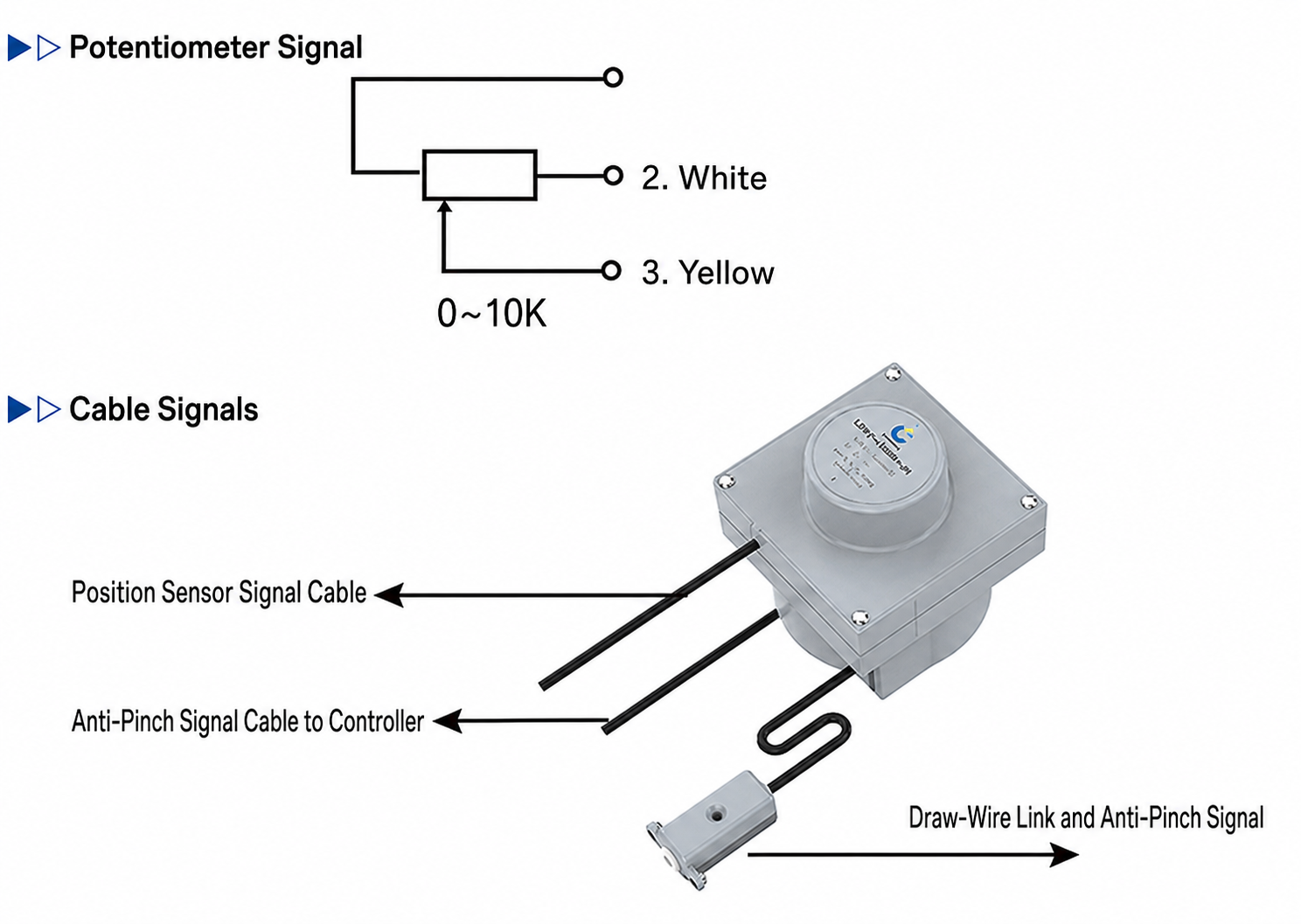
The position output uses a three-terminal potentiometer circuit. The controller reads the wiper position relative to the resistance ends and converts that value into sash travel. The wiring image also identifies separate cables for position feedback and the optional anti-pinch signal on the JK arrangement.
Position-Signal Connection
Use the wiring drawing supplied with the selected sensor to identify both resistance ends and the wiper. The reference image labels white and yellow conductors on the potentiometer circuit, but final conductor identification follows the delivered version. Check resistance smoothly across the full travel before connecting the controller.
Route the position-signal cable away from the sash drive motor, mains wiring and sharp metal edges. Secure the fixed cable so movement occurs only at the draw wire, not at the electrical connection. After connection, verify that raising the sash changes the controller input in the expected direction. If direction is reversed, correct the terminal or controller configuration according to the wiring instructions rather than changing the mechanical cable path.
Position Feedback Versus Anti-Pinch Input
The JK configuration shows a separate anti-pinch signal cable and a draw-wire link associated with that function. It is not part of the potentiometer resistance output. Connect each signal to the assigned controller input so the position value and obstruction state remain independent.
A valid position reading cannot replace obstruction detection. The controller may know the sash is descending, but only the configured safety input can report the relevant anti-pinch condition. Test both signals separately during commissioning and confirm the required motor response.
Continuity and Scaling Checks
With power isolated as required, check end-to-end resistance and wiper continuity while extending the cable slowly. The value should change smoothly without jumps or open circuits. After controller connection, calibrate the closed and working or full-open points and compare the displayed position with measured sash travel.
Installation, Cable Routing and Protection
Installation quality directly affects measurement repeatability and cable life. Mount the enclosure on a rigid part of the hood frame, keep the cable outlet aligned with sash movement and protect the full path from guides, counterweights, sharp edges and service access.
Mounting the Sensor Housing
The enclosure provides four side fixing holes and can be mounted directly or on an additional bracket. Choose an orientation that keeps the outlet facing the measured direction and leaves access to the cover, electrical cable and reel area. The bracket must remain rigid as the sash changes direction.
Position the sensor outside the contaminated work zone whenever the hood design allows. Do not place it where routine sash movement, counterweight travel or maintenance work can strike the housing. Before final tightening, cycle the sash manually and observe the cable path from closed to maximum opening.
Keeping the Draw Wire Straight
The cable should leave the sensor in a straight line. Keep angular deviation within 1 degree; over a 1,000 mm run, lateral displacement should not exceed 10 mm. Where the moving point does not align with the outlet, install a suitable pulley so the cable enters the sensor straight. The pulley must rotate freely and preserve the required travel ratio.
Avoid rubbing the cable on a hole edge, bracket or sash frame. Side rubbing can wear the cable and introduce friction or hysteresis into the position reading. Keep the cable path protected but visible enough for inspection.
Travel Margin and Safe Handling
Set the sensor position so neither the closed nor fully open sash reaches the reel’s mechanical end. Leave enough buffer for installation tolerances and controller stopping distance. The automatic sash motor should stop from position feedback before the sensor reaches full extension.
Do not pull out an unsecured sensor cable and release it to snap back. The spring return can damage the cable, reel or enclosure and can injure the installer. Hold the cable under control until its attachment point is secured. Keep cable speed below 1 m/s and instantaneous acceleration below 2 m/s2.
Maintenance Checks
Inspect cable alignment, attachment, surface condition and smooth return. Remove dust around the reel outlet before it affects movement. If the signal becomes unstable, check mechanical drag and electrical continuity before changing controller calibration. Replace a frayed, kinked or damaged cable assembly rather than continuing operation with an unreliable position signal.
Calibration, System Fit and Sensor Selection
The string pot sensor fits systems that can provide a straight linear measurement path and a compatible resistance input. Selection covers three linked choices: travel range, potentiometer resistance and mechanical attachment. The controller then maps the resistance signal to actual sash position.
Closed and Open Calibration
After installation, place the sash at its defined closed position and record the controller input. Move it to the normal working height or maximum calibrated opening and record the second point. The controller uses these values to calculate position across the travel. Check an intermediate position with a physical measurement to confirm the relationship is reasonable.
Repeat the full movement several times and verify that closed and open readings return consistently. A changing endpoint can indicate cable slip, attachment movement, reel drag or an electrical connection problem. Correct the cause before using the signal for motor limits or VAV airflow mapping.
Draw-Wire Versus Rotary Position Sensor
Choose this draw-wire sensor when the cable can follow the sash directly and remain protected. A rotary fume hood sash position sensor is more suitable when a pulley or shaft already provides a stable rotational relationship to sash movement. The two structures require different mounting, calibration and failure checks.
The draw-wire sensor measures linear extension directly but needs cable alignment and overtravel protection. The rotary sensor avoids a long draw-wire path but depends on pulley coupling, rotation ratio and shaft fit. Select the structure that fits the actual hood mechanism instead of treating the two sensors as interchangeable housings.
Automatic Sash and VAV Integration
The position signal can connect to an automatic fume hood sash controller for travel limits and movement logic. It can also support a VAV controller that relates sash opening to exhaust demand. The related automatic fume hood sash motor provides movement; the sensor only reports position.
For multiple horizontal sash panels or unusual motion, one linear cable may not describe the complete opening area. Provide the sash arrangement so the number of sensors and calculation method can be selected correctly.
Information Required for a Quotation
Send the hood and sash drawing, total travel, attachment point, available mounting space, cable route, controller model, required 5 kOhm or 10 kOhm input, anti-pinch option, electrical cable length, quantity and destination. XICHENG will match the sensor configuration, resistance, mounting arrangement and signal connections to the hood controls.
Frequently Asked Questions
Is this a 5 kOhm or 10 kOhm string potentiometer?
The product family includes a 1,000 mm / 5 kOhm configuration and a 0-10 kOhm configuration. Select the version that matches the controller’s resistance input and record it before calibration.
Can the full 1,000 mm cable travel be used as normal sash travel?
Leave margin at both ends instead of using the mechanical reel limits as routine controller stops. The usable sash travel must fit inside the cable range with allowance for installation tolerance and stopping distance.
How straight must the cable run?
Keep the cable within 1 degree of the outlet centerline, equivalent to no more than 10 mm lateral deviation over 1,000 mm. Use a suitable pulley when the sash path cannot meet this alignment directly.
Does the sensor control the automatic sash motor?
No. It supplies position feedback. The automatic sash controller reads that signal and commands the motor according to the calibrated limits and safety inputs.
Is the anti-pinch signal part of the position output?
No. The JK reference shows separate position and anti-pinch signal paths. They connect to different controller inputs and are tested independently.
What can cause an unstable position reading?
Common causes include cable rubbing, excessive angle, loose attachment, dust in the reel, damaged cable, slip-ring or conductor discontinuity and incorrect controller scaling. Inspect the mechanical path and signal continuity before recalibrating.
Contact the Xicheng Engineering Team Today
Send the sash drawing, travel, mounting location, cable path, controller input resistance, anti-pinch requirement and quantity. XICHENG will provide the matched draw-wire sensor configuration, connection information and quotation.
Manufacturing Head Office: No. 34 Zhenxing Road (Shengtaian Heavy Industrial Park B), Loucun, Guangming New Dist, Shenzhen, Guangdong, China
Direct Hotline / WhatsApp: +86 18126478161
Engineering Mailbox: fanalax@gmail.com