


Specifications
Sizes & Interfaces
Functions
Applications
Selection
Installation
FAQ
Contact
The BAC211 laboratory VAV terminal controller is a configured terminal-unit controller for projects that coordinate local temperature with the airflow delivered through a selected VAV terminal assembly. BAC211 combines temperature-related inputs, relay functions for reheat or fan-related control, an integrated rotary actuator, and BMS communication. It is not a complete room controller: the terminal, airflow sensor, upstream system, temperature sequence, reheat device, wiring, and commissioning requirements remain part of the delivered project configuration.
BAC211 at a Glance
Control Role
Use this VAV terminal controller where a defined terminal sequence must coordinate zone-temperature inputs, airflow conditions, and a selected rotary airflow-control device. BAC211 supports local-zone, AHU-supply-air, and VAV-exhaust-air temperature inputs together with reheat and fan-related interfaces.
Key Hardware Data
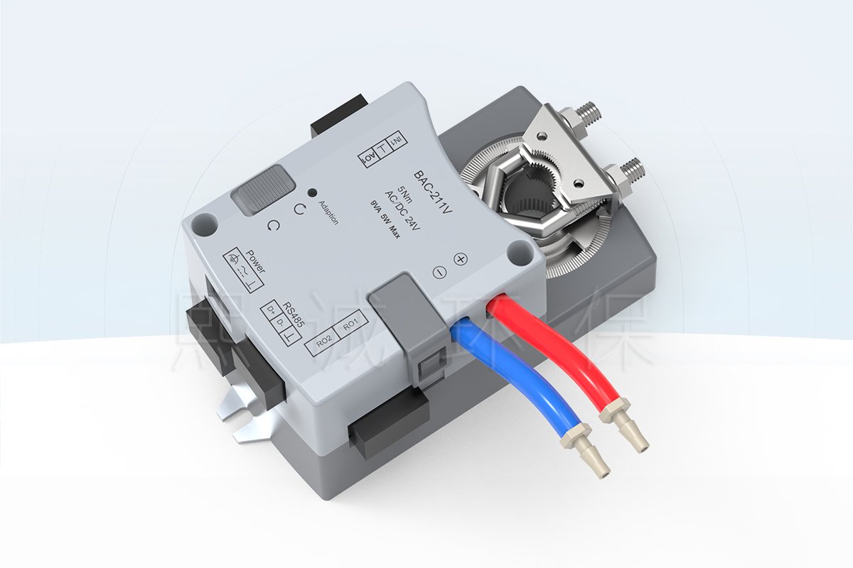
The controller uses a 5 N m integrated actuator with 60-second travel and AC/DC 24 V power. Check its 130 x 85 x 71.5 mm reference dimensions, 8 to 15 mm shaft range, and 35 mm minimum shaft length against the selected terminal assembly.
Configuration Inputs
Confirm the terminal airflow device, temperature sensors, reheat type, fan function, supply, I/O, BMS points, alarm and failure sequence, commissioning method, and supplied scope. Those project fields determine the delivered controller configuration.
Product Overview
Where the Laboratory VAV Terminal Controller Fits
A VAV terminal controller belongs at the terminal-unit level, where a selected airflow-control device, temperature signals, and optional reheat or fan functions need to follow one coordinated sequence. BAC211 is therefore positioned around the terminal and its local zone, rather than around an entire laboratory room or fume hood. The controller should be reviewed with the selected terminal airflow device, actuator interface, sensors, panel or BMS connection, and the project sequence.
Temperature and Airflow Control Boundary
Temperature inputs do not by themselves define terminal airflow, and an actuator position does not by itself prove the delivered airflow or zone condition. The final result depends on terminal sizing, airflow measurement, supply-air conditions, heat-load assumptions, sensor placement, reheat device, upstream pressure, sequence of operation, and commissioning. BAC211 provides controller and actuator interfaces within that system boundary; it does not replace the terminal unit, the reheat coil, sensors, BMS logic, balancing, or final acceptance testing.
How BAC211 Differs From BAC001
BAC211 is designed for VAV terminal temperature and airflow control. BAC001 serves a separate single-duct application and should be evaluated only when its I/O, terminal arrangement, and temperature-control sequence match the project. Select between them from the actual terminal architecture rather than from similar model names.
Product Selection Summary
Choose This Controller When
Choose the BAC211 VAV terminal controller when the project needs a terminal-level control assembly that combines a selected rotary airflow device with local temperature inputs and defined reheat, fan, relay, or BMS functions. It is appropriate when the terminal control sequence is known and the controller can be matched to the actual shaft, airflow device, sensors, reheat hardware, power supply, and network point list.
Conditions To Confirm Before Selection
- The VAV terminal type, airflow range, airflow measurement method, shaft size, rotation direction, mechanical load, and available mounting envelope.
- The zone-temperature, AHU-supply-air, and VAV-exhaust-air inputs required by the selected sequence, including sensor type and location.
- Whether modulating reheat hot water, on/off reheat hot water/electric heat, fan series/parallel, or another relay function is required.
- Power, analog and digital inputs, relay load, BMS protocol and points, display need, alarm/failure sequence, and commissioning responsibility.
Information Needed To Configure the Product
Provide the terminal drawing, airflow device and shaft information, airflow range, temperature-control objective, sensor list, reheat and fan requirements, power source, I/O schedule, BMS point list, alarm/failure sequence, quantity, destination, and commissioning responsibility. The documented configuration should identify the controller revision, actuator interface, sensor and reheat scope, relay functions, communication points, supplied documents, items requiring final confirmation, and commercial pricing.
Key Specifications
BAC-211V Controller and Interface Data
| Item | Product Data | Selection Note |
|---|---|---|
| Configuration | BAC211 / BAC-211V | Confirm final revision and terminal sequence. |
| Integrated actuator | 5 N m; 60 s travel | Verify shaft, rotation, load, and failure requirement. |
| Power | AC 24 V +/-10%, 9 VA max; DC 24 V +/-10%, 5 W max | Confirm protective device and combined load. |
| Temperature context | NTC local zone, AHU supply-air, and VAV exhaust-air temperature shown | Confirm installed sensor types and used inputs. |
| Reheat and fan interfaces | Modulating reheat; on/off reheat; fan series/parallel shown | Confirm the selected sequence and relay duty. |
| Network | RS-485; Modbus RTU/BACnet MSTP marked | Confirm protocol, point list, addressing, and BMS responsibility. |
| Mechanical reference | 8-15 mm shaft; 35 mm minimum shaft length | Verify the terminal actuator interface. |
Dimensions and Mounting Reference
The controller body has a 130 x 85 x 71.5 mm reference envelope and an approximate weight of 0.568 kg. Use these values with the terminal drawing to review shaft access, cable and tubing clearance, manual-operation access, enclosure space, and service access. Confirm the final mounting drawing against the controller revision supplied for the project.
Temperature, Airflow, and Terminal Functions
Temperature Inputs for Terminal Control
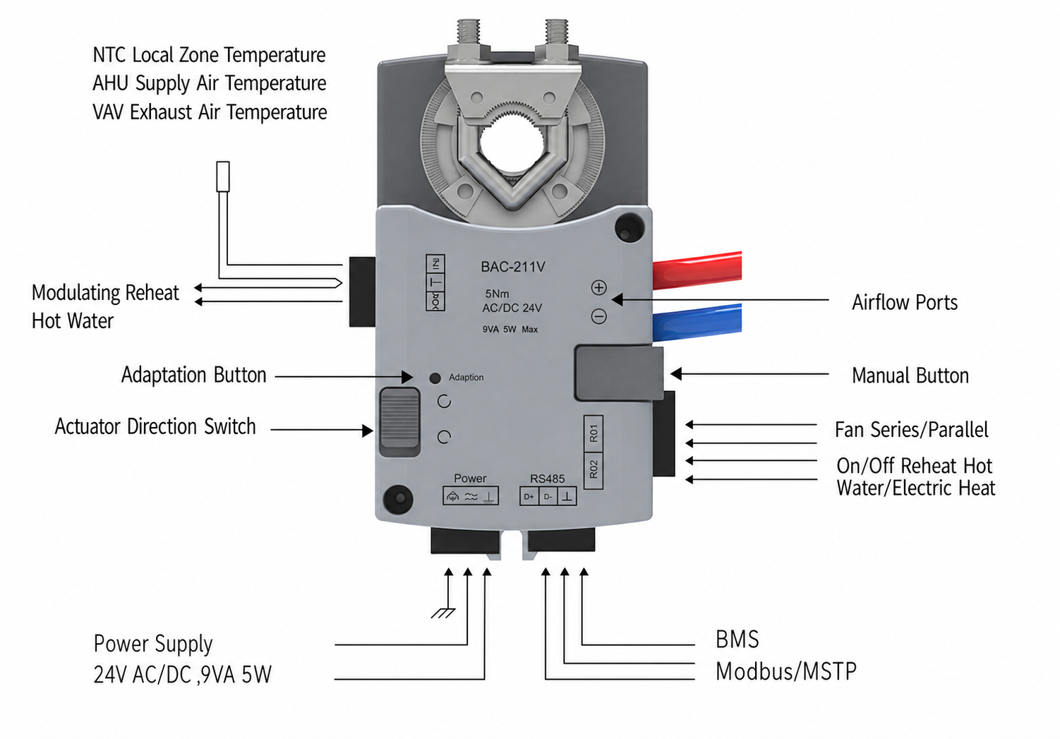
The BAC-211V function reference identifies NTC local-zone temperature, AHU supply-air temperature, and VAV exhaust-air temperature context. These inputs allow a configured terminal sequence to account for the local condition and the air delivered through the terminal. Confirm the actual inputs, sensor types, location, scaling, and sequence for each project.
Airflow Device and Integrated Actuator
The controller uses a 5 N m integrated rotary actuator with 60-second travel. Match it to the selected terminal device by shaft range, shaft length, rotation direction, torque/load, mechanical stops, mounting access, and required failure behavior. An integrated actuator simplifies the controller/actuator interface, but the VAV terminal, airflow pickup, damper blade or valve, and final airflow verification remain separate project considerations.
Reheat, Fan, Relay, and BMS Functions
Available BAC211 configurations support modulating hot-water reheat, on/off hot-water or electric reheat, and series or parallel fan functions. It also marks RS-485 BMS communication with Modbus/MSTP terminology. The final I/O schedule must identify which outputs are used, their electrical duty, the required interlocks, and which controller or BMS owns each command.
Adaptation and Manual Operation
The illustrated BAC-211V assembly includes adaptation, actuator-direction, and manual controls. Use these features with the approved terminal setup procedure. After any adaptation or manual movement, verify actual airflow, actuator direction, temperature response, relay behavior, and the selected sequence through the project commissioning method.
Applications and Project Fit
Laboratory VAV Terminal Zoning
Use BAC211 in a configured VAV terminal application where a local zone temperature condition must be coordinated with the terminal airflow device. It can form part of laboratory ventilation or HVAC zoning where the project specifies the airflow target, temperature sequence, reheat strategy, sensor package, network integration, and acceptance method. It is not a substitute for a room-wide supply/exhaust balance controller or a fume hood face-velocity controller.
When a Different Product Should Be Evaluated
Evaluate BAC001 when the procurement task is a separately defined single-duct controller. Evaluate a laboratory room controller when one controller must coordinate multiple supply/exhaust devices and the room pressure relationship. Evaluate a differential-pressure sensor when only measurement and signal transmission are required. Evaluate a fume hood controller when sash movement or face velocity defines the primary demand. These products may interoperate in a project but have different control boundaries.
VAV Terminal Selection Guide
Start With the Terminal, Not the Controller Name
Begin with the physical terminal and the environmental objective. Identify whether the selected device is a VAV box, a damper-based terminal, or another airflow-control arrangement; then confirm its airflow range, measurement method, shaft, actuator load, duct conditions, and accessible mounting space. The product name alone does not establish that one controller/actuator combination will fit every terminal. The BAC211 actuator and the selected terminal must be reviewed as a mechanical and control pair.
Define the Temperature Sequence
State what the zone-temperature sensor is intended to achieve and how it relates to airflow. In a terminal sequence, a local temperature condition can influence the airflow target, a reheat demand, a fan command, or a coordinated combination. BAC211 can use local-zone, AHU supply-air, and VAV exhaust-air temperature inputs with reheat or fan-related functions. The operating sequence is configured for the selected terminal and project. Define heating, cooling, deadband, airflow limits, reheat staging or modulation, fan behavior, alarms, and the action needed when a temperature input fails.
Coordinate Airflow and Reheat
Airflow and reheat must be reviewed together. Reducing airflow can change the air available to condition the zone, while reheat can change the air temperature without proving that the required ventilation airflow is present. The project sequence should therefore identify the minimum and maximum terminal airflow, any safety or ventilation minimum, the temperature setpoint strategy, the reheat device, the permitted fan modes, and the signals that command or verify each function. Final performance depends on the terminal, coil or electric-heater capacity, supply-air condition, sensor placement, and field balancing.
Review the I/O and Network Schedule Before Purchase
List every installed input and output rather than relying on a generic terminal diagram. BAC211 provides two analog inputs, one digital input, two relay outputs, and an RS-485 communication interface. Confirm which inputs are used for temperature or other sensor signals; which relay controls a fan, reheat device, or interlock; the electrical duty of those relay circuits; which BMS points are required; and whether Modbus RTU or BACnet MSTP is the applicable network implementation. This makes the controller configuration, electrical scope, and commissioning responsibility visible before equipment is ordered.
Acceptance Should Test the Selected Sequence
Commissioning should test the actual terminal sequence across the project operating states, not simply power the controller and observe actuator motion. Verify airflow at the selected terminal, zone-temperature response, sensor inputs, reheat or fan outputs, relay operation, BMS readings, alarms, and any defined failure state. Record the delivered configuration and measured results so future maintenance does not assume that an unrecorded wiring or setup change is a standard BAC211 function.
Engineering Boundaries and Project Responsibilities
Controller Scope Versus Terminal-System Scope
The BAC211 controller is one component in a terminal assembly. The terminal casing, damper or valve body, airflow pickup, shaft, reheat coil or electric heater, fan equipment, field sensors, electrical protection, ductwork, BMS programming, balancing, and safety acceptance are separate parts of the project scope. BAC211 provides controller and actuator interfaces, but complete terminal performance still depends on the selected airflow device, sensors, reheat or fan equipment, and control sequence.
Temperature Control Does Not Replace Ventilation Verification
A zone can reach a temperature setpoint while airflow is outside its intended range, particularly where reheat is active or the airflow device has been changed. Conversely, a terminal can deliver the target airflow without satisfying a temperature-control objective. Treat airflow measurement, temperature sensing, actuator travel, reheat output, and BMS values as related but separately verified conditions. The commissioning plan should state which instruments, locations, operating states, and acceptance criteria are used for each result.
Configuration Changes Require Reconfirmation
Recheck the controller configuration when the terminal size, shaft, actuator load, temperature sensor, reheat device, relay load, control signal, network interface, or sequence of operation changes. These changes can alter mechanical compatibility, electrical scope, signal scaling, output assignment, and commissioning requirements. Keeping the final point list, wiring drawing, control sequence, and installed revision together helps avoid treating a previous project configuration as a universal BAC211 standard.
Buyer Decision Notes
Use Key Product Data for Terminal Selection
Compare actuator torque and travel, power, mechanical interface, temperature inputs, relay functions, and RS-485 communication during terminal selection. Then confirm the terminal, sensors, reheat or fan equipment, I/O assignments, and BMS configuration for the project.
Installation, Wiring, and Commissioning
Checks Before Installation
Before installation, verify the controller revision, terminal shaft and rotation, mechanical clearance, selected sensor inputs, reheat and fan wiring, 24 V supply, relay load, BMS cable route, grounding/shielding, and the final sequence. Keep low-voltage signal wiring separate from higher-voltage relay circuits as required by the project wiring design.
Commissioning the Terminal Sequence
Confirm safe actuator travel, correct direction, sensor response, required airflow, temperature sequence, reheat or fan output, network points, alarms, and failure response. Record the final settings, measured results, approved controller and terminal revisions, selected sensor and reheat configuration, and any remaining items requiring confirmation before handover.
Technical Data, Configuration, and Documentation
Data Needed for the Final Configuration
Submit the VAV terminal drawing, airflow device, shaft data, airflow range, zone and supply-air conditions, sensor list, reheat and fan requirements, power, I/O and relay schedule, BMS points, alarm/failure sequence, quantity, destination, and commissioning responsibility. These fields define the delivered BAC211 configuration.
Documents for Installation and Handover
Depending on the selected configuration, documentation can include controller reference data, dimensions, terminal and wiring information, I/O schedule, BMS point list, sequence-of-operation details, and commissioning records. The final project documents define the installed assembly.
Related Products
Related Airflow and Laboratory Controls
For terminal branch airflow control without BAC211 temperature/reheat scope, evaluate the Duct Airflow Controller. For a room/zone pressure-and-airflow task, evaluate the Zone Pressure and Airflow Controller. Evaluate BAC001 separately when the project uses a single-duct terminal sequence and its available I/O and control functions match the application.
Frequently Asked Questions
Is BAC211 a room controller?
No. BAC211 is positioned as a VAV terminal temperature-and-airflow controller. A room controller has a broader task of coordinating room-level supply/exhaust devices and pressure relationships.
Does BAC211 include every reheat and fan function shown?
No. BAC211 supports reheat and fan-related interfaces, but the supplied configuration must identify the connected devices, output assignment, relay duty, and control sequence.
What temperature inputs are shown?
Available NTC temperature inputs cover the local zone, AHU supply air, and VAV exhaust air. Confirm the actual sensors and used inputs for the selected sequence.
What must be confirmed before ordering?
Confirm terminal type, airflow device and shaft, airflow range, sensor package, reheat/fan functions, power, I/O, BMS points, alarm/failure sequence, and commissioning responsibility.
Contact the Xicheng Engineering Team Today.
Send the VAV terminal drawing, airflow range, temperature inputs, reheat or fan requirement, and BMS point list. XICHENG can prepare a BAC211 configuration and pricing aligned with the selected terminal assembly.
Manufacturing Head Office: No. 34 Zhenxing Road (Shengtaian Heavy Industrial Park B), Loucun, Guangming New Dist, Shenzhen, Guangdong, China
Direct Hotline / WhatsApp: +86 18126478161
Engineering Mailbox: fanalax@gmail.com