


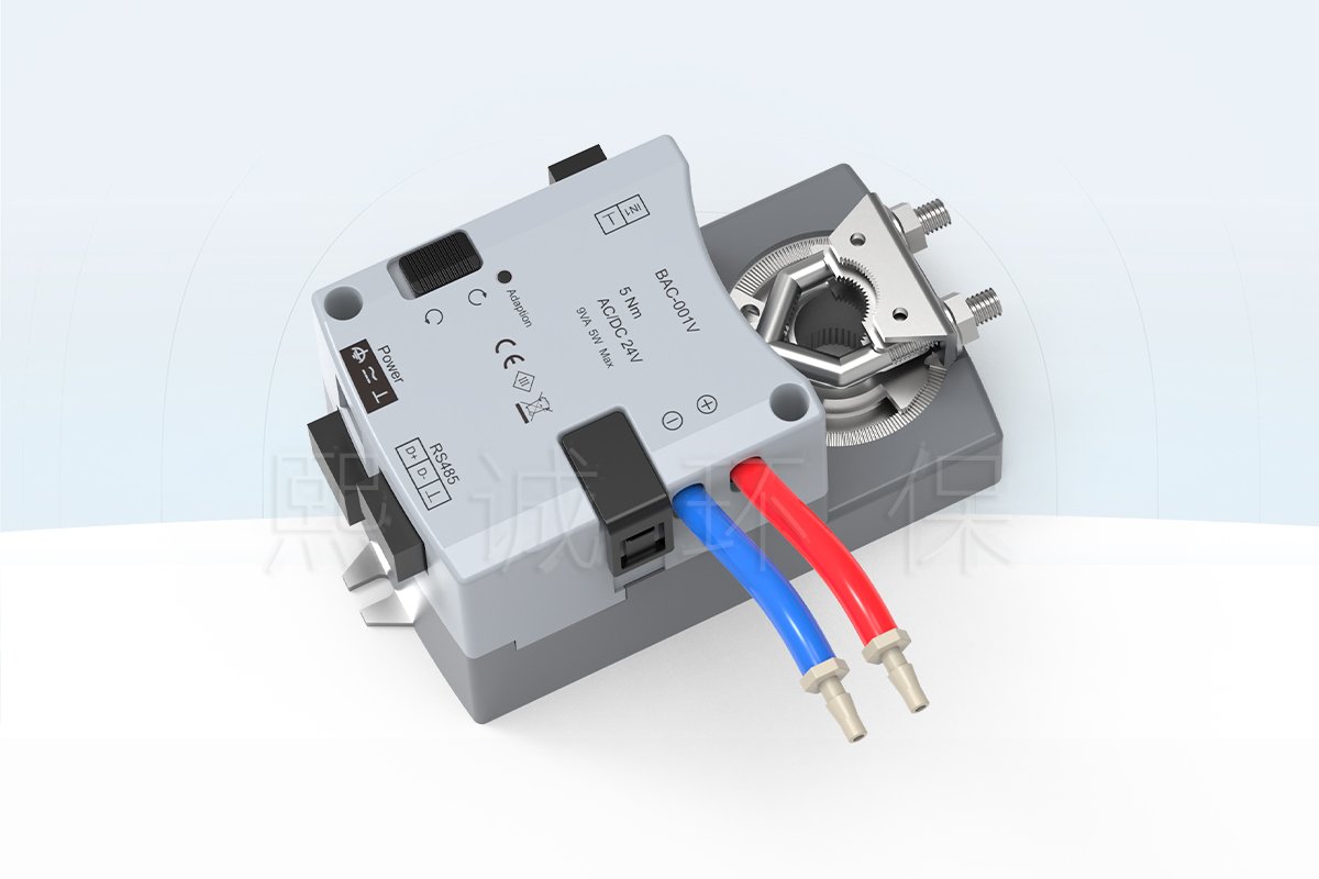
Single-Duct VAV Controller for Configured Temperature Control
This single-duct VAV controller is an integrated controller-and-actuator assembly for a VAV terminal whose damper position and airflow response are part of a temperature-control sequence. It combines a direct-mounted actuator, one temperature-input interface, differential-pressure measurement and an RS-485 communication connection in one enclosure. The product is intended to be selected with the terminal unit and its actual control sequence, rather than as a generic replacement for every damper actuator or room thermostat.
BAC001 is the XICHENG configuration identified for single-duct temperature control. Its published hardware covers a 5 N m or 10 N m actuator configuration, 60-second travel, 8-15 mm shaft interface, pressure-sensor ports and 24 V AC/DC power. The final assembly must still match the damper shaft, sensor type, duct pressure condition and BMS requirements on the project schedule.
What Buyers Need to Confirm First
- Terminal arrangement: confirm that the application is a single-duct VAV terminal and identify the damper shaft size, usable shaft length and mounting clearance.
- Control input: state whether the temperature input is used for local-zone, AHU supply-air or VAV single-duct temperature monitoring, then confirm the required sensor type.
- Airflow method: provide the airflow pickup arrangement, available duct-pressure conditions and required minimum, normal and maximum airflow values.
- Integration: identify the selected RS-485 protocol, network topology, power source and BMS point requirement before wiring is released.
Why an Integrated VAV Controller Changes the Installation Scope
An integrated VAV controller actuator reduces the number of field-mounted devices at the terminal, but it does not remove the engineering decisions around damper sizing, airflow pickup, temperature sensing or network commissioning. The actuator, pressure ports and controller are installed together; the connected terminal still needs correct mechanical alignment and the programmed sequence still needs to reflect the intended zone operation.
Product Boundary
This product is not a stand-alone room thermostat, a general-purpose 0-10 V damper actuator, or a complete air-handling-unit controller. It is also not automatically interchangeable with a fume hood airflow controller. Laboratory supply, exhaust or tracking applications should only use it where the single-duct terminal arrangement and the selected control logic have been confirmed. For a different terminal-control interface and published reheat/fan-related context, review the Laboratory VAV Terminal Controller separately.
Key Specifications and Physical Interface
The following values are published for the BAC001 family. They support preliminary selection and a drawing review; they are not a substitute for a project-specific terminal schedule. Confirm the selected torque, shaft connection, sensor and protocol before purchase.
| Selection field | Published BAC001 reference | What to confirm for the project |
|---|---|---|
| Integrated actuator | 5 N m or 10 N m configuration; 60 s travel | Required damper torque, stroke direction and control sequence |
| Shaft interface | 8-15 mm shaft; 35 mm minimum shaft length | Actual terminal shaft geometry and usable mounting length |
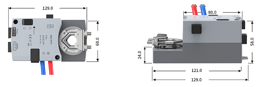
| Controller size | 129.0 x 69.0 x 58.0 mm reference envelope | Clearance around the terminal and access for wiring/tubes |
| Power | AC 24 V +/-10%, 9 VA maximum; DC 24 V +/-10%, 5 W maximum | Available supply and total panel/load design |
| Differential pressure sensor | +/-250 Pa; less than 3% of reading; less than 0.05 Pa zero drift | Pickup layout, pressure condition and airflow calculation basis |
| Environment | 0 to +50 C; 10-95% RH non-condensing | Actual enclosure and ambient condition |
Reference Dimensions Before Mechanical Release
The product drawing shows a 129.0 mm overall length, 69.0 mm body width and 58.0 mm height, with a 121.0 mm mounting-side depth and a 24.0 mm base profile. Use these as reference dimensions when checking access to the damper shaft, tubing ports, terminal cover and cable route. Do not infer the terminal-unit enclosure dimensions from the controller drawing.
Actuator Selection Is a Mechanical Check, Not a Keyword Choice
The published 5 N m and 10 N m options identify available actuator configurations. They do not prove that either torque is suitable for a particular VAV damper. The purchase request should identify the damper manufacturer or drawing, blade arrangement, shaft size, operating pressure and any spring or linkage resistance. That information allows the actuator configuration to be selected against the actual terminal rather than against a nominal duct diameter.
Published Environmental Limits
The published operating condition is 0 to +50 C at 10-95% relative humidity without condensation; the stated storage condition is -20 to +50 C. Where the controller will be installed in a damp, corrosive, outdoor or high-temperature location, the enclosure, cable entry and exposed components require a separate suitability review.
Control, Airflow Sensing and Local Service Controls
A single-duct VAV controller does not create useful control merely by rotating a shaft. It needs a defined relationship between temperature demand, damper position and the airflow measurement used by the selected sequence. BAC001 provides the physical elements for that arrangement: integrated actuation, differential-pressure ports, a temperature input, an adaptation control, a direction switch and a manual control.
Integral Differential-Pressure Measurement
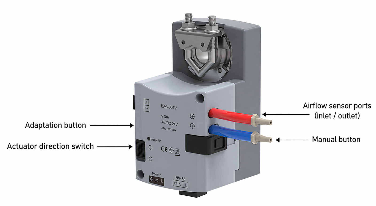
The published pressure-sensor range is +/-250 Pa, with accuracy stated as less than 3% of reading and zero drift below 0.05 Pa. The red and blue ports are identified as the airflow-sensor inlet and outlet. Their tubing must connect to the terminal’s intended pressure pickup arrangement with no kinks, leaks, crossed connections or unsupported tubing. The controller cannot correct an incorrectly installed pickup or an airflow coefficient that does not match the terminal.
Adaptation, Direction and Manual Operation
The functional view identifies an adaptation button, actuator direction switch and manual button. These controls help with commissioning and mechanical checks, but they do not replace documented sequence setup, airflow balancing or acceptance testing. Before operating a terminal, verify that the commanded direction opens and closes the intended damper path and that the displayed or commissioned response follows the selected control logic.
Temperature Demand and Airflow Demand Are Related but Not Identical
For a temperature-control application, the selected temperature input supplies the demand signal used by the configured control sequence. Airflow feedback is derived from the terminal’s pressure pickup arrangement. The two should be commissioned together: a temperature-input problem can produce the wrong demand, while an airflow-pickup problem can make a correctly driven actuator appear to deliver the wrong air volume. The submittal should state the temperature sensor, airflow pickup and intended minimum/maximum airflow values together.
Do Not Treat Actuator Position as Airflow Proof
Damper position may be useful for a mechanical check, but it is not a measured airflow value. The terminal’s installed pressure condition, pickup design, damper characteristic and ductwork determine the actual result. Commissioning must therefore include the specified airflow method, not only a visual check that the shaft turns.
Temperature Input and BMS Integration
BAC001 provides one published temperature-input interface. The source product sheet names NTC-10K and NTC-20K sensor options and describes the input for local-zone, AHU supply-air or VAV single-duct temperature monitoring. Select the sensor and its installation location from the actual sequence. A temperature label alone does not define whether the project needs room sensing, supply-air sensing or another control point.
Temperature Sensor Selection
Provide the sensor type, location, wiring length and control purpose with the enquiry. A local-zone sensor can serve a different decision than a supply-air temperature sensor, even when both are nominally temperature inputs. The final control drawing should identify the sensor type supported by the delivered configuration rather than assuming all NTC variants are interchangeable.
RS-485 Communication
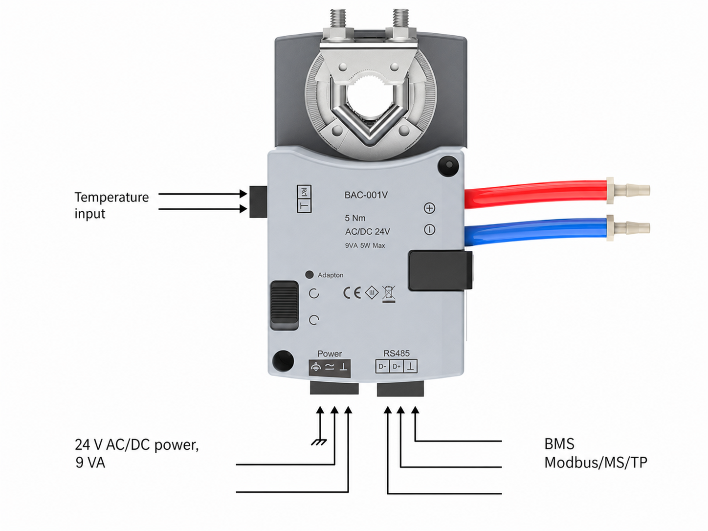
The source identifies RS-485 communication and names Modbus RTU / BACnet MS/TP, with a published 9.6-76.8 kbps communication range. Confirm the protocol selection, device address, baud rate, termination, cable route and required BMS points before the network is closed. Protocol names indicate available integration paths; they do not by themselves define the selected point map or front-end graphics.
Power and Wiring Sequence
The published power values are AC 24 V +/-10% at 9 VA maximum or DC 24 V +/-10% at 5 W maximum. Use the project electrical design to check transformer capacity, common reference and protection. Keep the temperature-input cable, power cable and communications connection identifiable at the terminal so that subsequent service does not rely on tube colour or actuator position alone.
What the BMS Schedule Must State
At minimum, state the controller tag, selected protocol, network address, monitored values, commanded values, alarm or status requirements, temperature-sensor purpose and the sequence used at occupied, setback, override and fault conditions. Where the project uses a local display or supervisory controller, include the responsibility boundary for configuration and graphics.
Applications and Product Fit
This VAV temperature controller is suited to a configured single-duct terminal arrangement where temperature input, airflow measurement and damper actuation must be coordinated. Typical evaluation contexts include commercial HVAC zone terminals, VAV terminal units associated with AHU supply air, and laboratory airside systems that use a compatible single-duct terminal. The application must be defined by its actual terminal and control sequence, not by the building type alone.
Single-Duct VAV Terminal Units
The direct-mounted actuator and pressure-sensor ports make BAC001 relevant when a VAV terminal requires integrated hardware rather than a separately mounted controller and actuator. Confirm the terminal shaft, pickup geometry, damper torque, mounting clearance and airflow setpoints before it is selected. A terminal with a different shaft form, pressure pickup or control architecture may require another configuration.
AHU Supply-Air and Zone-Temperature Context
The published product information names local-zone, AHU supply-air and VAV single-duct temperature monitoring as temperature-input contexts. These are different applications and should not be combined into one generic sequence. The approved control drawing must show what the input measures, how it influences the damper, and what other devices own heating, cooling, fan or central-air-handling functions.
Laboratory Airside Projects
In a laboratory project, this controller can be reviewed for a compatible terminal application, but it is not a substitute for a fume hood face-velocity controller or a room-pressure controller. A fume hood exhaust sequence has its own face-velocity sensing, sash logic, emergency mode and system interlocks. A room-pressure sequence has its own reference pressure and airflow tracking requirements. Select the product that matches the controlled object and the documented sequence.
When a Different Product Is the Better Fit
Use a dedicated fume hood controller when the primary input is face velocity or sash position. Use a zone pressure controller when the controlled variable is room differential pressure. Use a more extensive terminal-control configuration when the project needs the specific interface scope published for the Laboratory VAV Terminal Controller. These boundaries prevent a nominally similar actuator/controller from being selected for the wrong sequence.
Installation and Commissioning Checks
The controller should be installed only after the terminal mechanical arrangement and the approved wiring documentation are available. Protect the actuator from torsion during mounting, ensure the shaft is within the stated interface range, and keep access to the manual, adaptation and connection points after the terminal is closed.
Mechanical Installation
- Confirm the terminal damper is mechanically free and the shaft is 8-15 mm with at least 35 mm usable length.
- Select the published 5 N m or 10 N m configuration against actual damper torque and operating conditions.
- Mount the controller without forcing the actuator body against the terminal enclosure or obstructing the manual control.
- Check direction before final linkage or clamp tightening; correct direction is a system requirement, not an assumed default.
Sensor Tubes and Electrical Connections
Route the inlet/outlet pressure tubes to the intended pickup points and protect them from crushing, condensate traps and accidental disconnection. Connect the approved 24 V supply, selected temperature sensor and RS-485 network in accordance with the issued terminal wiring diagram. Do not use the illustration alone as a field wiring release when the project has a controlled drawing or point list.
Commissioning Sequence
Verify power first, then actuator direction and travel. Confirm the temperature input has a credible value for its stated location, then verify the pressure-tube orientation and the airflow method selected for the terminal. Configure network settings before final BMS handover. Balance and acceptance should demonstrate the agreed minimum, normal and maximum airflow response under the installed duct conditions, rather than relying only on a successful manual stroke.
Information to Keep with the Terminal
Record the controller tag, torque version, damper shaft size, terminal model, temperature sensor, pressure pickup, airflow setpoints, control sequence, network address, protocol and commissioning result. This information makes later service and replacement traceable without reinterpreting the entire system from device labels.
Single-Duct VAV Controller Selection Summary
Select BAC001 when the project needs an integrated actuator/controller arrangement for one VAV duct path, one selected temperature input, differential-pressure sensing and RS-485 building-management integration. The product should be configured from the terminal mechanics and the control drawing, not selected solely because it includes a VAV actuator.
Choose This Product When
- The controlled object is a single-duct VAV terminal with an 8-15 mm shaft and sufficient mounting length.
- The sequence needs a selected temperature input together with measured differential pressure and damper actuation.
- A 5 N m or 10 N m, 60-second integrated actuator is suitable for the actual terminal damper.
- The installation can use the approved 24 V supply and a specified RS-485 protocol arrangement.
Do Not Select It from the Product Name Alone
Do not use a single-duct VAV controller as a general replacement for an arbitrary damper actuator, a room thermostat, a fume hood face-velocity controller or a room differential-pressure controller. The term “VAV controller” describes a product family, not one universal sequence. The mechanical terminal, sensing arrangement and programmed logic decide whether this configuration is appropriate.
Information Needed for a Configured Quotation
Provide terminal-unit make or drawing, shaft dimensions, damper torque information, required minimum/normal/maximum airflow, pressure pickup arrangement, temperature sensor and location, operating condition, power supply, selected protocol, BMS point list, quantity and destination. Include the control schematic and terminal schedule where available. The returned configuration should identify the actuator torque, temperature-input arrangement, communication selection and any remaining installation dependencies.
Related Product Paths
For a terminal controller with its own published temperature, reheat/fan-related and interface context, see the Laboratory VAV Terminal Controller. For duct airflow control with a different application focus, see the Duct Airflow Controller. For fume hood face-velocity control, review the Fume Hood Face Velocity Controller.
Frequently Asked Questions
Is BAC001 a VAV box controller with an actuator?
It is an integrated single-duct VAV controller and actuator arrangement. The published BAC001 configuration includes 5 N m or 10 N m actuator options, a 60-second travel time, differential-pressure sensing and one temperature-input interface. The compatibility decision still depends on the particular VAV terminal and damper.
What shaft sizes can the controller mount on?
The published shaft range is 8-15 mm, with a 35 mm minimum shaft length. Confirm usable shaft length, clearances and torque requirements from the actual terminal drawing before ordering.
Does it support Modbus or BACnet?
The source identifies RS-485 communication and names Modbus RTU and BACnet MS/TP. Confirm the supplied protocol selection, addressing and point list for each project before commissioning.
Can it be used for a laboratory fume hood?
Not as a direct substitute for a fume hood controller. A fume hood needs a control sequence built around face velocity, sash condition, alarms and exhaust-system coordination. BAC001 should be evaluated only when it is controlling a compatible single-duct terminal within the wider laboratory airside design.
Contact the Xicheng Engineering Team
For a single-duct VAV controller configuration, send the VAV terminal drawing, damper shaft dimensions, required airflow setpoints, temperature-sensor requirement, pressure pickup details, selected BMS protocol and control sequence. Xicheng can review the mechanical and integration inputs and return the applicable controller configuration and pricing.
Manufacturing Head Office: No. 34 Zhenxing Road (Shengtaian Heavy Industrial Park B), Loucun, Guangming New Dist, Shenzhen, Guangdong, China
Direct Hotline / WhatsApp: +86 18126478161
Engineering Mailbox: fanalax@gmail.com