


Description
Transparent Air Damper for Visible Duct Inspection
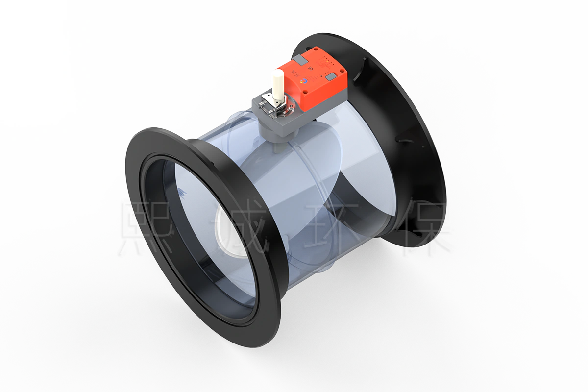
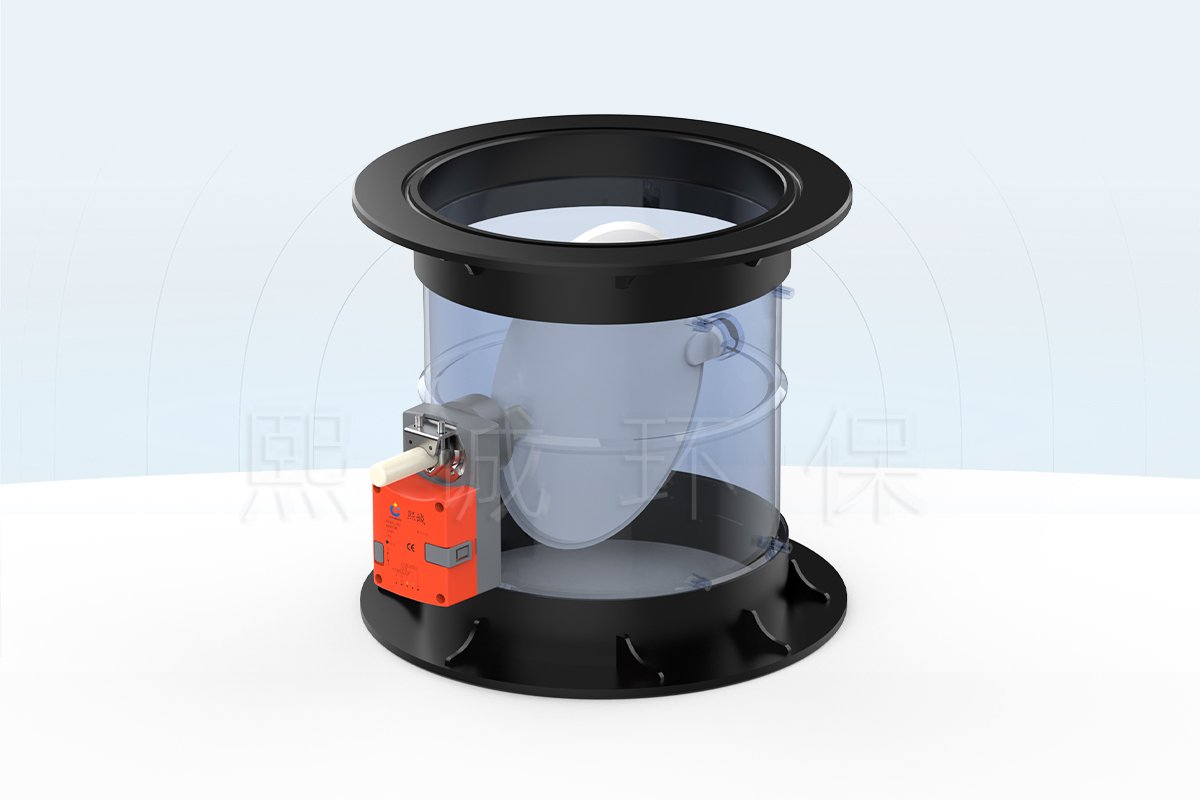
A transparent acrylic air damper combines a round ventilation damper with a clear body that keeps the blade and internal surface visible. It is intended for branches where an operator, technician or instructor needs to check blade movement, deposits, condensation or general internal condition without first opening the duct. The available product is a 250 mm or 315 mm round damper with manual or electric operation.
The clear body changes how the damper can be inspected, but it does not turn the damper into an airflow meter. Actual airflow still depends on fan operation, duct pressure, system resistance and blade position. Use measured airflow whenever the ventilation design requires a numerical flow rate or acceptance value.
The inspection benefit is greatest when the viewing purpose is defined before installation. The clear section can help verify blade travel, reveal visible deposits or condensation and support teaching or demonstration work. It should therefore face an accessible, illuminated location rather than being hidden above equipment or wrapped in opaque insulation.
Key Decision Data
- Available openings: 250 mm and 315 mm round bodies, with the flange and overall envelopes listed in the specification section below.
- Operating options: manual adjustment or electric actuation; the motorized version requires the project voltage, command, feedback, travel-time and power-loss position.
- Visible construction: a one-piece acrylic body keeps the blade, silicone edge and internal surface in view for inspection.
- Closure reference: the manufacturer states sealing up to 98%, but this is not a certified leakage class without a stated test pressure and method.
- Primary limitation: visual confirmation does not measure airflow, differential pressure, containment or contaminant concentration.
These points allow an initial product fit check before reviewing dimensions and materials. The main reasons to continue with this transparent air damper are a compatible 250 mm or 315 mm branch, a genuine need for visual inspection and an operating method that can be installed with adequate access.
Transparent Acrylic Air Damper Selection Summary
Choose This Product When
- A clear view of the blade or internal duct condition has practical operating, demonstration or maintenance value.
- The duct can use a 250 mm or 315 mm round flanged connection.
- Acrylic and the silicone blade edge are compatible with the actual air stream and cleaning method.
- Manual adjustment or a project-selected electric actuator meets the operating sequence.
Choose Another Damper When
Select a different product when the application requires pressure-independent airflow control, a certified leakage class, fire or smoke protection, or a material better suited to the process chemistry. A VAV Venturi air valve serves pressure-compensated variable-airflow duties, while a constant airflow regulator maintains a mechanical fixed-flow setting. Neither function is created by the transparent body itself.
Information Needed for Initial Selection
Start with the duct opening, airflow and pressure condition, air-stream composition and temperature, required operating mode, installation orientation and available actuator clearance. For an electric unit, also define power supply, command signal, position feedback, travel time and the required position after a power loss.
Also state the reason for choosing a transparent body. Visual blade confirmation, cleanliness inspection and demonstration use impose different access and lighting requirements. This information helps determine body orientation, operator position and whether the manual or motorized version will remain practical after installation.
Key Specifications and Available Dimensions
Key Product Specifications
| Specification | Available Configuration | Buyer Check |
|---|---|---|
| Product type | Round transparent duct damper | For ventilation air, not liquid service |
| Body material | High-transparency acrylic | Check chemistry, temperature, cleaning agents and impact exposure |
| Body construction | One-piece formed body with smooth surfaces | Support the connected duct independently |
| Blade edge | Fully bonded silicone | Check compatibility and closure duty |
| Nominal openings | 250 mm and 315 mm | Coordinate flange and duct dimensions |
| Operation | Manual or electric | Define access or actuator requirements before ordering |
| Electric drive | Brushless motor/actuator option | Specify voltage, command, feedback, travel time and fail position |
| Blade closure | Silicone-edged blade; manufacturer states sealing up to 98% | Specify a test method when a formal leakage limit is required |
Manual and Electric Dimensional Envelope
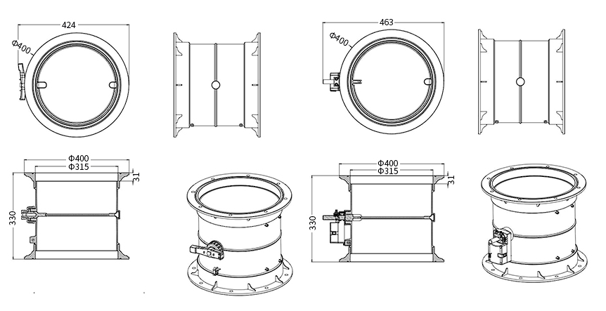
The 315 mm drawing below shows how the manual operator and electric actuator change the overall width while the 400 mm flange outside diameter, 315 mm opening and 330 mm body height remain common to the illustrated size.
| Nominal Opening | Operation | Flange OD | Overall Width | Body Height |
|---|---|---|---|---|
| 250 mm | Manual | 343 mm | 364 mm | 310 mm |
| 250 mm | Electric | 343 mm | 405 mm | 310 mm |
| 315 mm | Manual | 400 mm | 424 mm | 330 mm |
| 315 mm | Electric | 400 mm | 463 mm | 330 mm |
The overall-width values include the manual operator or electric drive shown in the dimensional drawing. Provide the mating flange details and available service clearance so the drilling pattern, fasteners and operator location can be coordinated before production.
Blade Closure and Leakage Requirements
The silicone-edged blade is intended to improve contact around the closed perimeter, and the manufacturer states sealing up to 98%. This percentage is not a formal leakage class because no test pressure, leakage unit or test standard accompanies it. When shutoff performance matters, provide the required standard, test pressure and allowable leakage so the acceptance method is defined before ordering.
Closure also depends on blade alignment, seal condition, actuator end position and duct distortion. A suitable seal cannot compensate for a body pulled out of shape by misaligned flanges or for an actuator that stops before the blade reaches its intended closed position.
Acrylic Construction and Visual Inspection Value
One-Piece Transparent Body
The clear acrylic body is formed as one piece with smooth internal and external surfaces. This construction keeps the blade visible from several angles and avoids an opaque housing around the airflow path. The smooth interior also reduces unnecessary projections into the duct, although the page does not assign a pressure-drop value to the body.
Silicone-Edged Blade
A fully bonded silicone edge follows the blade perimeter and improves contact in the closed position. The blade, silicone edge, shaft penetrations and connection joints should all be considered when the application has a defined closure requirement. The material label of the body alone does not describe the compatibility of every exposed component.
What Visual Inspection Can Confirm
With suitable lighting and access, the clear acrylic air damper allows a technician to see whether the blade has moved, whether deposits or condensation are accumulating and whether the internal surface appears clean after maintenance. These checks can shorten fault finding when the relevant condition is visible.
Transparency cannot confirm airflow rate, containment, pressure balance or gas concentration. A blade can appear open while the fan is stopped, and some contamination may be difficult to see. Keep the airflow sensor, alarm and commissioning measurements required by the ventilation design.
Material Compatibility
Review acrylic and silicone against the complete exposure: chemical identity, concentration, temperature, moisture, cleaning agent, cleaning frequency and possible impact. Avoid assuming that a clear plastic body has the same chemical or temperature range as PP, stainless steel or coated metal. Non-abrasive cleaning methods help preserve visibility and reduce surface scratching or crazing.
Normal operation and cleaning should be checked separately. An air stream may be compatible with acrylic while a concentrated solvent, disinfectant or hot cleaning process damages the surface. Include both routine and upset conditions, and keep actuator-side hardware away from dripping condensate or cleaning liquid.
External mechanical conditions matter as well. Acrylic should not carry the weight of connected ductwork, absorb vibration from a fan or compensate for flange misalignment. Independent supports and even gasket compression protect the clear body from local stress that may not be visible immediately after installation.
Manual and Motorized Operation
Manual Acrylic Air Damper
The manual configuration suits a branch that is adjusted locally and does not need remote commands. Position the operator where it remains visible and reachable after insulation, adjacent equipment and service panels are installed. If the blade must remain at a fixed setting, define how the operator is locked and how the final position is recorded.
Motorized Acrylic Air Damper
The electric configuration adds a brushless motor/actuator to move the blade. The actuator package is selected around the actual duty rather than inferred from the acrylic body: open/close or modulating command, supply voltage, torque, travel time, position feedback, cycle frequency and power-loss position all affect the supplied configuration.
Torque must be sufficient to overcome blade and seal friction without transferring unnecessary load into the acrylic body. Runtime should match the process sequence: a locally adjusted ventilation branch may tolerate slow movement, while an automated process may require a defined response and position feedback. State the expected number of cycles so the drive is not selected only from its nominal torque.
Control and Supply Boundary
A motorized damper moves in response to its command; it does not automatically measure or regulate airflow unless the project also provides the required sensor and controller. State whether the order covers only the damper and actuator or also requires a control panel, airflow measurement, BMS interface or site commissioning. Keeping these items explicit prevents blade-position feedback from being mistaken for measured airflow.
For open/close service, define the energized and de-energized positions and whether end switches are required. For proportional service, define the command range, feedback range and usable blade-angle limits. If airflow is the controlled variable, the control schematic must show where it is measured and which controller converts the measurement into an actuator command.
Applications and Product Selection
Suitable Laboratory and Process-Ventilation Applications
This acrylic ventilation damper is most useful where visibility serves a defined operating purpose. Examples include demonstration and teaching systems, test rigs, selected laboratory supply or exhaust branches and process-ventilation lines where technicians inspect blade movement or internal cleanliness. Suitability still depends on the air stream, pressure, temperature and risk assessment.
For teaching and demonstration systems, the body can show how blade movement changes the open area, but numerical airflow should still be displayed from a separate instrument. For inspection duties, locate the clear section where staff can see the full blade and the areas most likely to collect deposits. For automated branches, retain access to both the viewing area and actuator rather than optimizing only for duct alignment.
Select the Size and Operating Method
- Choose the 250 mm or 315 mm opening from the duct layout and required airflow.
- Check the flange outside diameter, body height and operator envelope against available space.
- Confirm that acrylic, silicone and the remaining exposed components suit the air stream and cleaning procedure.
- Select manual operation for local adjustment or electric operation for remote movement.
- For a motorized unit, define command, feedback, travel time and power-loss position.
- State the required airflow, closure or inspection acceptance criteria.
When a Different Air Damper Is More Suitable
Use an opaque corrosion-resistant damper when visibility is unnecessary and another body material better matches the chemistry. Select a VAV damper or Venturi air valve when the primary requirement is controlled variable airflow. Choose a mechanical constant-airflow device when the branch must maintain one fixed flow without continuous actuator control. Fire, smoke and certified isolation duties require products designed and tested for those functions.
Information Required for Quotation
Provide the duct diameter, design airflow, available pressure, air-stream composition and temperature, cleaning method, manual or electric operation, actuator power and signals, installation orientation, flange requirement, quantity and destination. Include the duct drawing and control sequence when the damper connects to an automated ventilation system.
XICHENG will return the selected diameter, manual or electric configuration, dimensional drawing, actuator details and included components. Where a leakage limit or airflow-control requirement is specified, the quotation should also identify the applicable test or control package rather than relying on visible blade position.
Installation, Commissioning and Maintenance
Support and Flange Alignment
Support the connected ductwork so external weight, vibration and misalignment are not transferred into the acrylic body. Bring the mating flanges into alignment before tightening fasteners, distribute the clamping load evenly and avoid using the damper to pull misaligned duct sections together. Confirm that gaskets and sealants are compatible with the acrylic.
Access, Visibility and Cleaning
Orient the clear section so the inspection area can be seen and illuminated after installation. Leave room for the manual operator or electric actuator, wiring and replacement. Protect the surface during construction, then clean it with compatible non-abrasive materials. Solvents or aggressive tools that scratch, cloud or craze the acrylic reduce the main value of the product.
Commissioning Checks
Cycle the blade through its required movement and check for binding, abnormal load and contact with adjoining components. For an electric damper, verify command, direction, end positions, feedback and power-loss behavior. Measure airflow or closure performance using the project acceptance method; visual blade position alone is not an acceptance test.
Record the commanded position and observed blade position at the main operating states. If airflow is measured, record the airflow, duct pressure and fan condition at the same time. This baseline makes later inspection more useful because a visible change can be compared with the original operating condition rather than judged from appearance alone.
Routine Inspection
Inspect the body for cracks, stress marks or clouding; check the silicone edge for damage or separation; and examine fasteners, shaft points and the actuator mounting. Deposits or condensation visible through the body should be investigated against the process and maintenance plan rather than treated only as a cosmetic issue.
Related Laboratory Air Dampers
Compare the round VAV butterfly damper when variable airflow is the main requirement and a clear body is unnecessary. Use the constant airflow regulator for a passive fixed-flow duty, or review the VAV Venturi air valve when pressure compensation and controlled variable airflow define the selection.
Frequently Asked Questions
Which Sizes Are Available?
The documented configurations have 250 mm and 315 mm nominal openings. Each size has a different flange outside diameter, body height and manual or electric operator envelope.
Does the Transparent Body Show the Airflow Rate?
No. It shows visible blade movement and internal condition. Numerical airflow requires an airflow sensor, balancing instrument or another measurement method.
Can the Acrylic Air Damper Be Motorized?
Yes. Manual and electric versions are available. For an electric unit, specify the voltage, command, feedback, travel time, torque requirement and power-loss position.
Does the Stated 98% Sealing Equal a Certified Leakage Class?
No. The stated sealing percentage does not include a formal leakage test standard, pressure or leakage unit. Specify those conditions when the project requires a certified or measurable leakage limit.
Is Acrylic Suitable for Every Laboratory Exhaust Stream?
No. Check the chemical, concentration, temperature, moisture and cleaning agents against the acrylic body, silicone edge and other exposed components.
How Should the Clear Body Be Maintained?
Use compatible non-abrasive cleaning materials, avoid solvents that can cloud or craze acrylic and inspect the body for scratches, cracks, deposits and stress marks.
Contact the Xicheng Engineering Team Today
Send the duct size, airflow and pressure condition, air-stream composition and temperature, cleaning method, manual or electric operating requirement, installation drawing and quantity. XICHENG will prepare a matching configuration, dimensional information and quotation.
Shenzhen Office: No. 34 Zhenxing Road (Shengtaian Heavy Industrial Park B), Loucun, Guangming New Dist, Shenzhen, Guangdong, China
WhatsApp: +86 181 2647 8161
Engineering Mailbox: fanalax34@gmail.com