


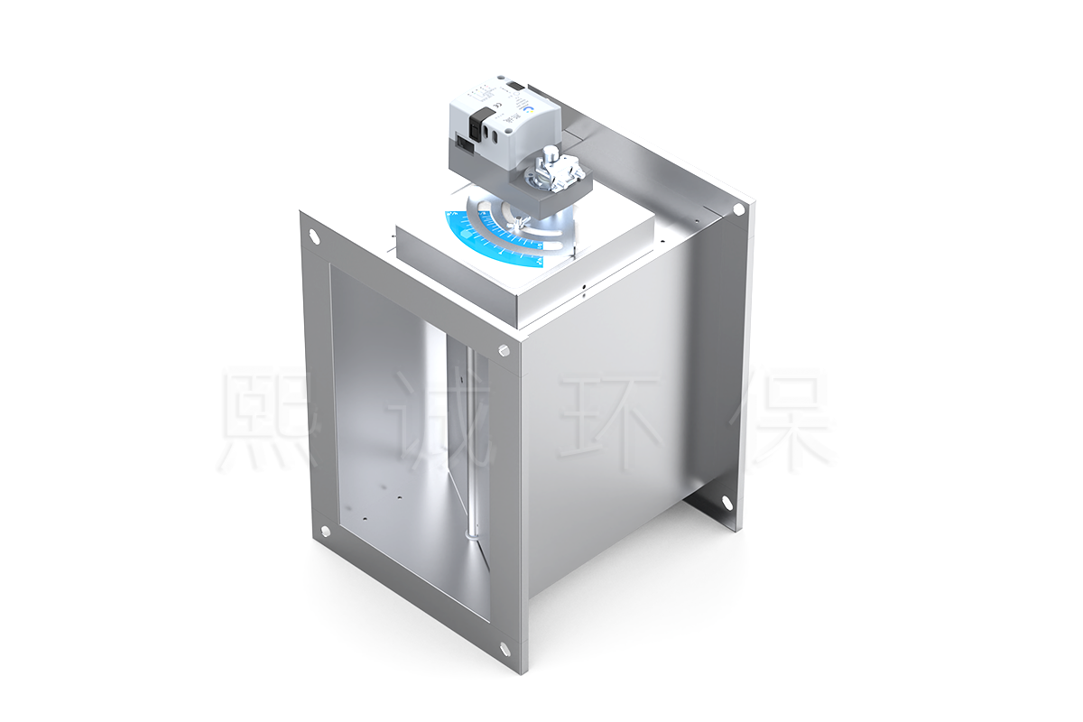
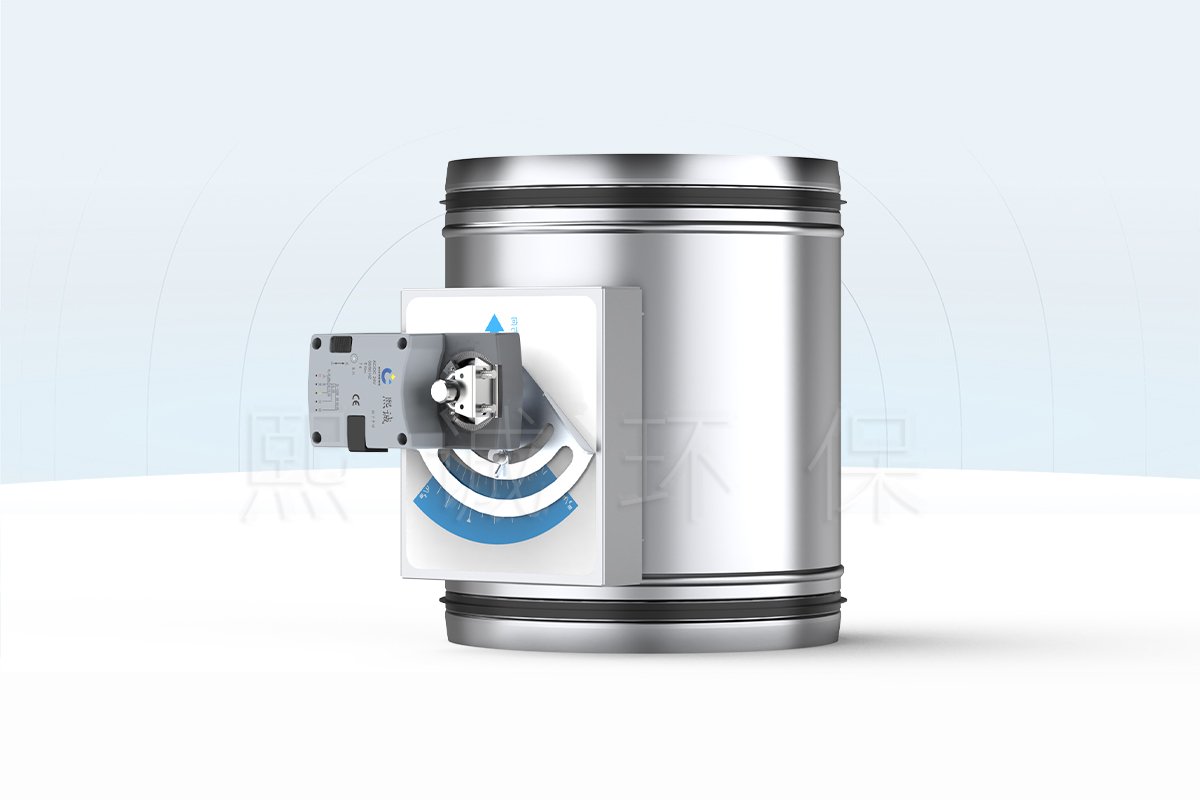
Description
Two Fixed Airflow States from One CAV Damper
A two-position constant air volume damper provides two selected airflow levels from one duct device. Its mechanical CAV core responds to pressure changes around the active setting, while an electric actuator moves the adjustment mechanism between two commissioned positions. This arrangement suits a branch that needs normal and boost, occupied and setback, or standby and process airflow without continuously modulating through a VAV range.
The two states are defined by airflow values, not simply by the words open and closed. Both values must fall within the selected damper’s flow and pressure range, and both must be measured during commissioning. Actuator position confirms movement; it does not prove that the fan and duct system delivered the scheduled airflow.
This makes the product different from a two-position shutoff damper. A shutoff damper normally moves between open and closed positions, while this CAV damper moves between two calibrated airflow settings and continues to regulate mechanically around the active setting. State A and State B should therefore be named by their operating purpose and airflow, such as 300 m³/h setback and 750 m³/h occupied duty.
Key Decision Data
- Control concept: two commissioned airflow setpoints with mechanical constant-airflow regulation around the active state.
- Working differential pressure: 150-1000 Pa for the stated product configuration.
- Adjustment ratio: 3.5:1; both requested setpoints must remain inside the selected size’s available range.
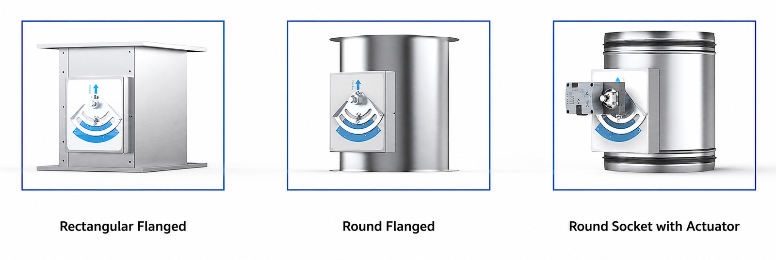
- Body options: round or rectangular construction in galvanized steel or 304 stainless steel, with flange or customized socket connections.
- Operating temperature: 10-50 degrees C, subject to the selected actuator and material limits.
- Installation requirement: provide at least 1.5D of straight inlet duct and enough pressure for both system states.
The product is a good first choice when two numerical airflow duties are required but continuous modulation is unnecessary. It should not be selected solely because the control signal has two positions; the mechanical CAV range, duct pressure and commissioned airflow values must also match.
Two-Position CAV Damper Selection Summary
Choose This Product When
- The ventilation sequence requires two repeatable, numerical airflow setpoints.
- A mechanical constant-airflow mechanism is preferred at each selected state.
- The branch can use a documented round or rectangular configuration.
- The actuator power, commands, feedback and power-loss position can be defined.
- The available pressure supports both airflow states.
Choose Another Damper When
Use a constant airflow regulator when one passive airflow setting is sufficient. Select a VAV butterfly damper when the command must move continuously with an airflow, pressure or process demand. A two-position CAV damper is also not a fire damper, smoke damper or certified shutoff device.
Information Needed for Initial Selection
Define State A and State B airflow, available pressure at both conditions, round diameter or rectangular width and height, supply or exhaust duty, material, connection, temperature, installation orientation and actuator sequence. State which command selects each airflow and what the damper must do after loss of power or signal.
Also identify any fan-speed change, room-pressure sequence or neighboring branch that changes at the same time. Both airflow states can be stable only when the fan and duct system provide enough pressure after the complete sequence changes.
Key Specifications, Dimensions and Airflow Ranges
Key Product Specifications
| Specification | Available Value | Selection Note |
|---|---|---|
| Operating concept | Two selected constant-airflow states | Schedule a numerical airflow for each state |
| Mechanical mechanism | Blade, air bag, spring plate and shaped cam | Self-operated regulation around the selected setting |
| Stated flow adjustment ratio | 3.5:1 | Final two setpoints must fit the selected size range |
| Stated differential-pressure range | 150-1000 Pa | Check both operating states and fan conditions |
| Operating temperature | 10-50 degrees C | Confirm all actuator and material limits |
| Body forms | Round or rectangular | Use the matching dimension and flow dataset |
| Body material | Galvanized steel or 304 stainless steel | Review the actual supply or exhaust air stream |
| Standard sheet thickness | 1.2 mm | Other thicknesses can be customized |
| Connections | Flange or customized socket | Coordinate sealing and insertion details |
| Inlet straight length | Minimum 1.5D | Keep transitions and disturbances away from the inlet |
| Factory service | Airflow calibration available | Site verification is still required after installation |
| Referenced test document | JG/T 436-2014 | State the required test report or compliance document when ordering |
Round CAV Damper Dimensions
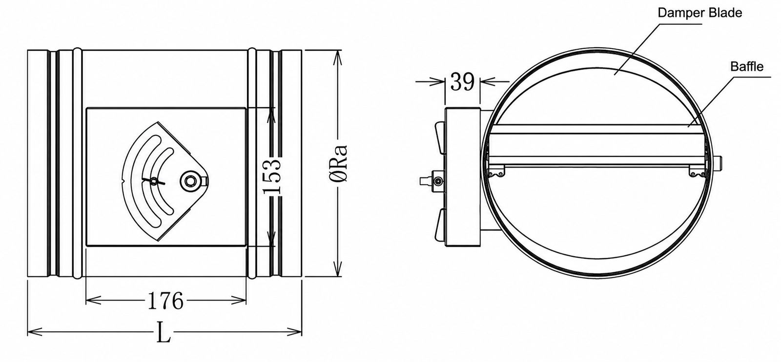
The round construction uses a 300 mm body length across the listed sizes. The drawing identifies the body diameter, adjustment enclosure and internal blade arrangement that must remain accessible when the actuator is added.
| Nominal Size | Body Diameter | Length |
|---|---|---|
| 100 mm | 99 mm | 300 mm |
| 125 mm | 124 mm | 300 mm |
| 160 mm | 159 mm | 300 mm |
| 200 mm | 199 mm | 300 mm |
| 250 mm | 249 mm | 300 mm |
| 300 mm | 299 mm | 300 mm |
| 315 mm | 314 mm | 300 mm |
| 400 mm | 399 mm | 300 mm |
The round table describes the mechanical body. Add the selected actuator envelope and connection details when checking service space.
Rectangular CAV Damper Airflow Selection
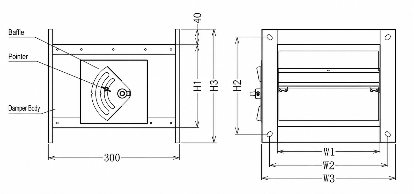
The rectangular body is scheduled by duct width and height. Its 300 mm depth, internal blade and external adjustment enclosure should be coordinated with the duct support and actuator service space.
| Duct Size | Minimum Airflow | Maximum Airflow | Stated Error | Minimum Total Pressure Difference |
|---|---|---|---|---|
| 200 x 100 mm | 144 m3/h | 504 m3/h | +/-10% | 60 Pa |
| 300 x 100 mm | 216 m3/h | 756 m3/h | +/-10% | 60 Pa |
| 300 x 200 mm | 432 m3/h | 1512 m3/h | +/-10% | 60 Pa |
| 400 x 200 mm | 576 m3/h | 2016 m3/h | +/-10% | 60 Pa |
| 400 x 250 mm | 720 m3/h | 2520 m3/h | +/-10% | 60 Pa |
| 500 x 250 mm | 900 m3/h | 3150 m3/h | +/-10% | 60 Pa |
| 500 x 300 mm | 1080 m3/h | 3780 m3/h | +/-10% | 60 Pa |
| 500 x 500 mm | 1800 m3/h | 6300 m3/h | +/-10% | 60 Pa |
| 600 x 400 mm | 1728 m3/h | 6048 m3/h | +/-10% | 60 Pa |
| 600 x 600 mm | 2592 m3/h | 9072 m3/h | +/-10% | 60 Pa |
Both selected airflow states must remain inside the minimum and maximum range for the chosen rectangular size. The 60 Pa minimum total-pressure difference belongs to the rectangular size table, while the separately stated 150-1000 Pa range describes the broader operating envelope. Include both selected airflow values and both pressure conditions in the inquiry.
How the Mechanical CAV Mechanism Regulates Airflow
Blade, Air Bag, Spring and Cam
Airflow acts on a movable blade and the force is amplified through an automatically inflated air bag. This force moves the blade toward the closing direction as duct pressure rises. A spring plate and shaped cam apply force in the opposite direction. The balance between these forces allows the regulator to hold airflow near its selected setting while pressure changes within the applicable range.
Passive Regulation at the Active Setting
The mechanical CAV core does not need external power to perform this regulating action. Electrical power is used by the actuator that changes the selected state, not by the air bag and spring mechanism that responds around that state. This distinction matters when defining power-loss behavior: the actuator may stop or return to a selected position, while the mechanical core continues to respond around whichever setting remains engaged.
Two Selected Airflow States
State A and State B are two calibrated positions within the available range of the chosen damper. Each position corresponds to a target airflow under the selected operating conditions. The two values do not need to be described as low and high, but the control schedule must pair each command with one numerical airflow and one intended operating purpose.
The ratio between the two states must remain practical for the selected body. A very low State A can fall below the mechanism’s useful control range, while a high State B can exceed available pressure or create excessive velocity and noise. Selecting a larger body only for the high state may therefore weaken regulation at the low state; both points must be evaluated together.
Pressure and Accuracy Conditions
Constant-airflow performance depends on operating inside the applicable pressure envelope and using the correct installation conditions. The rectangular selection table states a +/-10% error and a 60 Pa minimum total-pressure difference for its listed sizes, while the product-family description states a 150-1000 Pa differential-pressure range. Keep these conditions attached to their respective data rather than applying one number to every round and rectangular configuration.
Factory Setting and Site Verification
Factory airflow calibration can establish the requested settings before shipment. After installation, both states still need measured verification because fan performance, fittings, transitions, leakage and available pressure can change the delivered airflow. Do not rotate or alter the calibrated adjustment without recording the new setting and repeating the airflow test.
Verify repeatability as well as one-time accuracy. Command A-B-A and B-A-B transitions, allow the mechanical mechanism to settle and compare the repeated readings. A damper that reaches each position but does not reproduce the airflow needs investigation of pressure, actuator travel, linkage and inlet conditions.
Actuator Switching and Two-State Control
What the Actuator Changes
The actuator moves the CAV adjustment mechanism between the two selected positions. It does not replace the blade, air bag, spring and cam mechanism, and it does not by itself calculate airflow. The supplied actuator must have the travel, torque and mounting arrangement needed by the chosen round or rectangular body.
Command, Feedback and Power-Loss Position
Define the actuator voltage, the signal or contacts that select each state, position feedback if required, travel time and the position expected after loss of power or command. Avoid leaving State A tied implicitly to de-energized operation; the electrical schedule should state the relationship directly.
Where a BMS or process controller sends the command, define the delay, minimum dwell time and transition interlocks. Rapid repeated switching can prevent the airflow from stabilizing and may increase actuator cycling. If boost airflow depends on a fan-speed command, the sequence should state whether the fan or damper moves first and how successful operation is proved.
Two-State Control Schedule
| Schedule Field | State A | State B |
|---|---|---|
| Operating purpose | Project-defined normal, occupied or standby duty | Project-defined boost, setback or process duty |
| Airflow setpoint | Numerical project value | Numerical project value |
| Command | Defined contact or signal state | Defined contact or signal state |
| Actuator position | Commissioned mechanical position | Commissioned mechanical position |
| Measured airflow | Recorded during acceptance | Recorded during acceptance |
| Power-loss behavior | Define whether State A or another position is required | Define whether State B or another position is required |
Position Feedback Is Not Airflow Proof
An auxiliary contact or actuator feedback signal can show that the shaft reached a position. It cannot detect a stopped fan, blocked duct, insufficient pressure or changed system resistance. Add airflow measurement or a proof device when the process needs confirmation that the scheduled airflow is actually present.
A practical BMS point list can distinguish commanded state, actuator position and measured airflow as separate values. This prevents an “open” status from being interpreted as successful boost ventilation when airflow has not been measured.
Applications and Detailed Product Selection
Normal and Boost Ventilation
A two-position CAV damper can keep a branch at its normal airflow and move to a higher selected value when an occupancy, process or alarm command calls for boost ventilation. Check fan capacity, noise, downstream pressure and room balance at the boost condition. The sequence should also define when the damper returns to normal and whether an operator reset is required.
Occupied and Setback Airflow
The same two-state arrangement can reduce supply or exhaust airflow during a defined unoccupied period while retaining a commissioned minimum. Setback must still satisfy the ventilation and safety requirements of the space. Where laboratory work may continue outside the normal schedule, provide an override and coordinate the corresponding supply, exhaust and pressure-control response.
Select Round or Rectangular Construction
Choose a round body for a circular branch and use the documented diameter and length table to coordinate the connection. Choose a rectangular body when the duct is scheduled by width and height or the required flow falls within the rectangular table. Do not convert round dimensions into a rectangular selection or assume the rectangular +/-10% value applies to every round configuration.
Select Material and Connection
Galvanized steel suits conventional clean ventilation duties. Select 304 stainless steel when cleaning or air-stream conditions require it, but review the blade, air bag, springs, seals and actuator environment as well as the casing. Flanged and customized socket connections are available; include the gasket, insertion and sealing requirements in the duct detail.
For exhaust service, include condensate, deposits and cleaning chemicals in the material review. The mechanical regulator contains moving and flexible components, so a suitable outer casing alone does not establish compatibility for the complete airflow path.
Information Required for Quotation
For each damper tag, provide State A and State B airflow, available pressure at both states, duct size and body form, supply or exhaust duty, operating temperature, air-stream composition, material, connection, installation orientation, actuator power and commands, feedback, power-loss position, quantity and destination. Attach the duct layout and control sequence when fan operation, alarms or room pressure change with the selected state.
Installation, Commissioning and Maintenance
Airflow Direction and Inlet Conditions
Install the damper in the airflow direction marked on the body and provide at least 1.5D of straight duct at the inlet. Keep abrupt transitions, elbows and other disturbances far enough away for stable entry conditions. Remove burrs and debris before installation so they do not obstruct the blade or adjustment mechanism.
Flanged and Socket Connections
Align flanged connections without distorting the casing and use a compatible compressible gasket. A socket connection requires suitable sealing material and even fastening around the joint. Leave access to the actuator, adjustment mechanism and any position indication after the surrounding ductwork is complete.
Two-State Airflow Test
Command State A, allow the system to stabilize, then record the command, actuator position, airflow and pressure. Repeat for State B and test transitions in both directions. The acceptance record should show that each command repeatedly produces its scheduled airflow under the relevant fan condition.
Where the two states occur under different fan or room operating modes, test the real combinations rather than forcing both values under one artificial condition. Record the available pressure at the damper so an airflow shortfall can be separated from a setting or mechanism problem.
Power-Loss and Interlock Test
Verify the damper response after loss of power and loss of command. Where the state change is interlocked with a fan, occupancy schedule, process signal or alarm, test the complete sequence rather than the actuator alone. Confirm that any feedback shown to the BMS matches the actual position and is not labelled as measured airflow unless a flow sensor is present.
Inspection and Maintenance
Inspect blade movement, linkage, air bag, spring and cam components, actuator mounting, wiring, seals and casing condition. Recheck both airflow states after an actuator replacement, setting change, major duct modification or fan-system change. Preserve the calibrated setting unless an authorized change is followed by new airflow measurements.
Related Laboratory Airflow Products
Use the constant airflow regulator when one passive airflow setpoint is sufficient. Compare the round VAV butterfly damper when a continuous command must change airflow, or the constant volume Venturi air valve when the specification requires a Venturi pressure-compensation mechanism rather than the blade, air-bag, spring and cam mechanism used here.
Frequently Asked Questions
Is This an Open/Close Shutoff Damper?
No. The two positions correspond to two selected airflow values. The product is not presented as a certified isolation, fire or smoke damper.
Does It Provide Continuous VAV Control?
No. This configuration switches between two airflow states. A continuously varying demand requires a VAV control configuration.
Can the Two Airflow Setpoints Be Selected for the Project?
Yes. Both values must fit the airflow and pressure range of the selected body and must be verified after installation.
Does the Damper Require Power to Regulate Airflow?
The mechanical CAV core regulates around the active setting without external power. The actuator requires power to move between the two settings.
Is an Airflow Sensor Included?
Not inherently. Specify airflow measurement or a proof device when the control system must confirm actual airflow rather than actuator position.
Are Round and Rectangular Configurations Available?
Yes. Round sizes from 100 to 400 mm and rectangular sizes from 200 x 100 to 600 x 600 mm are documented, with separate dimension and airflow data.
Contact the Xicheng Engineering Team Today
Send both airflow setpoints, duct size, pressure conditions, operating sequence, material and connection, actuator power and signals, installation drawing and quantity. XICHENG will prepare a matching two-position CAV damper configuration, technical schedule and quotation.
Shenzhen Office: No. 34 Zhenxing Road (Shengtaian Heavy Industrial Park B), Loucun, Guangming New Dist, Shenzhen, Guangdong, China
WhatsApp: +86 181 2647 8161
Engineering Mailbox: fanalax34@gmail.com