


Description
Pressure-Compensated Venturi Valve for Classified Ventilation Areas
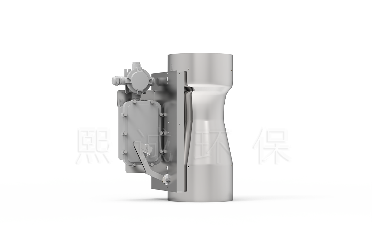
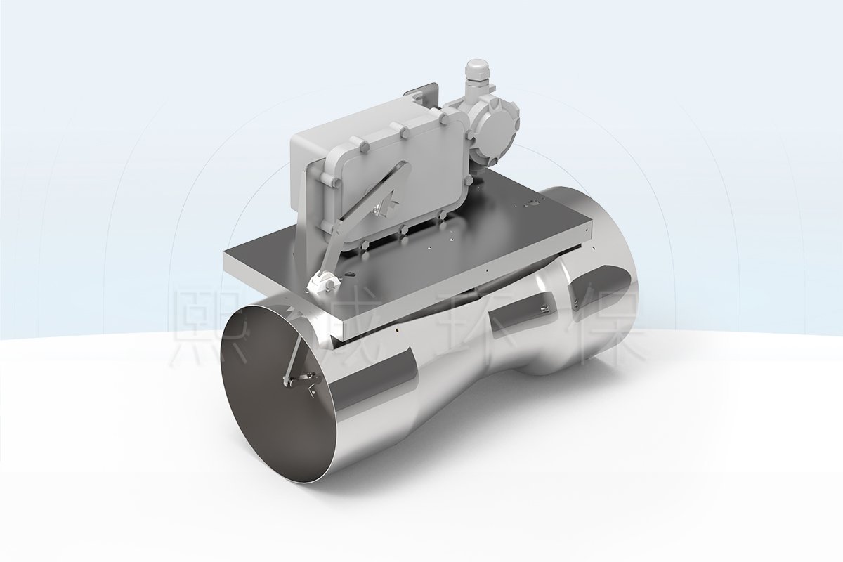
A Venturi air valve with explosion-proof actuator regulates variable airflow while using electrical actuation selected for the identified hazardous location. The Venturi cone/spring mechanism compensates for duct-pressure changes; the actuator changes the commanded airflow setpoint.
Selection has two independent duties. The airflow duty defines body size, range, pressure, material and control package. The hazardous-area duty defines zone or division, gas/dust group, temperature class, ambient conditions, protection concept, glands, junction box and documentation. Both must be approved for the delivered configuration.
Key Decision Data
- Body materials: ABS, aluminum alloy and stainless steel 304/316 configurations are available, with material and coating selected for the actual air stream and external environment.
- Working differential pressure: 150-750 Pa for the characterized Venturi configurations.
- Airflow coverage: individual-body ranges depend on material and size; combined-valve arrangements can extend the family selection range up to 10,000 CMH.
- Control performance: airflow accuracy is stated at no more than +/-5% within the selected operating range, with an under-one-second reference for the applicable high-response configuration.
- Control interfaces: applicable packages support 2-10 V command or feedback and RS485 Modbus RTU communication.
- Hazardous-area requirement: the exact actuator model, Ex marking, certificate, ambient limit, cable entries and installation conditions must match the project classification.
The airflow values identify which valve body may fit the branch. They do not establish hazardous-area acceptance. Conversely, a correctly certified actuator does not prove that the selected body covers the required minimum, normal, maximum and emergency airflow.
What Is Included
The base product includes the Venturi body, internal mechanism and project-selected actuator arrangement. FHC10/FHC12/FHC100 packages can serve fume hood control; QAVC10/ZPC211 can serve duct airflow or room pressure; OBAC211 can participate in room-temperature control. The quotation must identify controller, actuator, signals and supplied accessories.
Choose This Product When
- The branch is in a formally classified gas, vapor or dust area.
- A Venturi pressure-compensating mechanism and variable airflow are required.
- ABS, aluminum or stainless construction can be matched to the air stream.
- The project can provide the exact hazardous-area classification and review the actuator certificate.
- Mechanical, electrical and airflow commissioning will be coordinated.
Information Required Before Configuration
- Minimum, normal, maximum and emergency airflow, together with available duct pressure at each operating mode.
- Required body material, duct connection, installation orientation and available actuator service clearance.
- Process gases or dusts, concentration, temperature, humidity, condensate and cleaning exposure.
- Hazardous-area standard, zone or division, gas/dust group, temperature class and ambient-temperature range.
- Actuator power, command and feedback signals, required fail position, controller location and BMS interface.
With these inputs, the quotation can identify the valve size and material, applicable airflow range, actuator and controller scope, connection drawing, electrical accessories and documentation supplied for the selected configuration.
What Explosion Protection Does Not Mean
Explosion protection addresses the ability of identified electrical equipment to avoid becoming an ignition source under certified conditions. It does not make the valve a blast damper, fire damper, smoke damper or explosion-isolation device. A component certificate does not automatically certify the complete airflow assembly.
For a non-classified area, use the VAV Venturi Air Valve. For a butterfly mechanism in a classified area, compare the VAV Air Damper with Explosion-Proof Actuator.
Key Performance, Sizes and Hazardous-Area Configuration
The values below describe available Venturi configurations that can be paired with a project-selected explosion-protected actuator. Valve performance and hazardous-area suitability are separate approval fields. Final values belong on the valve schedule, actuator certificate review and electrical submittal.
Family Performance References
| Specification | Available Configuration |
|---|---|
| Working differential pressure | 150-750 Pa |
| High-response configuration | Less than 1 second |
| Airflow-control accuracy | No more than +/-5% within the stated operating range |
| Materials | ABS, aluminum alloy, stainless steel 304/316 and selected coated configuration |
| Analog control | 2-10 V command and/or feedback with the applicable package |
| Communication | RS485 Modbus RTU with the applicable integrated controller |
| Family selection range | 80-10,000 CMH using single or combined-valve arrangements |
The response value describes the high-response configuration, not every actuator or the complete room-control loop. The accuracy statement remains tied to the selected range and operating pressure. The 10,000 CMH upper value requires an applicable combined-body arrangement and must not be assigned to one valve.
Use these figures as selection boundaries. The final schedule must identify the applicable body range and response configuration, while the electrical submittal separately identifies the actuator model, marking, certificate and area suitability.
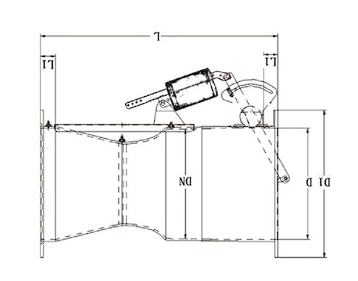
ABS Body Sizes
| ABS Size | D1 | D2 | Overall Length | Published Airflow Range |
|---|---|---|---|---|
| 110 | 165 mm | 102 mm | 482 mm | 80-350 CMH |
| 160 | 215 mm | 150 mm | 455 mm | 100-700 CMH |
| 200 | 257 mm | 190 mm | 578 mm | 150-1,600 CMH |
| 250 | 330 mm | 248 mm | 662 mm | 250-1,800 CMH |
| 250 compact | 330 mm | 248 mm | 532 mm | 250-1,500 CMH |
| 315 | 365 mm | 302/297 mm | 641 mm | 300-2,000 CMH |
| 355 | 435 mm | 352 mm | 765 mm | 300-2,500 CMH |
Aluminum Alloy Body Sizes
| Aluminum Size | OD | ID | Overall Length | Published Airflow Range |
|---|---|---|---|---|
| DN100 | 99.5 mm | 96.5 mm | 270 mm | 20-220 CMH |
| DN150 | 149.5 mm | 146.5 mm | 390 mm | 50-500 CMH |
| DN200 | 199.4 mm | 196.4 mm | 503 mm | 80-1,100 CMH |
| DN250 | 249.2 mm | 246.2 mm | 553 mm | 120-1,600 CMH |
| DN300 | 299.4 mm | 296.4 mm | 683 mm | 160-2,000 CMH |
| DN350 | 353.2 mm | 350.2 mm | 755 mm | 200-2,500 CMH |
ABS and aluminum dimensions use different conventions and cannot be mixed. Stainless steel 304/316 dimensions, coating scope and airflow range are returned on the project drawing. An aluminum value below the 80 CMH family selection statement also requires confirmation of the body, pressure and characterized setpoint range.
Check connection geometry as carefully as airflow. The external diameter, internal diameter and overall length affect transitions, supports and actuator access. A body that covers the airflow range may still be unsuitable if the installed envelope conflicts with adjacent equipment or leaves no service clearance.
Single and Multi-Valve Selection
Use one body when its published range covers every required operating mode. Dual, triple and four-body assemblies extend capacity when one body is insufficient. The combined schedule must identify individual body size and range, total minimum and maximum airflow, common connection, actuator strategy and the method used to combine feedback.
Parallel bodies can move together or operate in stages. Coordinated movement needs matched scaling; staging needs enable thresholds, overlap and a response when one body is unavailable. Verify each valve as well as total branch airflow during acceptance.
The common inlet and outlet arrangement must distribute airflow across the bodies. Poor plenum geometry can produce unequal loading even when every actuator receives the same command. The project drawing should show body spacing, structural support, actuator removal paths and how individual feedback is exposed to the controller or BMS.
Venturi Mechanism and Material Selection
The shaped body accelerates airflow through the Venturi section. Differential pressure moves the cone and spring assembly to help preserve the characterized airflow relationship within the selected 150-750 Pa range. The actuator changes the target for VAV operation.
ABS Construction
Flame-retardant ABS provides a molded non-metallic body. Final suitability requires the exact resin, temperature, chemicals, concentration and every exposed component. Use the ABS size table for selection.
Aluminum Alloy Construction
The aluminum family uses its own diameter and length convention and can be supplied with a project-selected coating. Confirm alloy, coating coverage and compatibility with both the air stream and external classified environment.
Stainless Steel Construction
Stainless steel can be selected where strength, temperature, cleanability or corrosion requirements justify it. Grade, coating and dimensions must be returned for the project. Do not copy aluminum dimensions without confirmation.
Pressure and Performance Boundary
The less-than-one-second response and no-more-than +/-5% airflow accuracy apply to the identified high-response Venturi configuration within its operating range. They are not universal guarantees for every actuator, combined-body assembly or complete room-control loop.
Explosion-Protected Actuation and VAV Control
The source identifies an isolation/explosion-protected actuator and references CNCA-C23-01:2019 and PCEC-C23-01:2019 implementation requirements for explosion-proof electrical products. The exact model, certificate number and Ex marking are not universal family values and must be returned for the project.
Actuator Approval Fields
Confirm manufacturer, model, certificate, marking, zone/division suitability, gas or dust group, temperature class, ambient range, torque or thrust, stroke, travel time, power, command, feedback and fail behavior. Include cable glands, junction box and wiring method in the same review.
Controller Location and Electrical Boundary
The controller can be located outside the classified area while the approved actuator and electrical accessories remain at the valve, depending on the design. The hazardous-area dossier must show which equipment is inside the boundary and how signals and power cross it.
Fume Hood and Duct Control Options
FHC packages support sash or face-velocity-based hood exhaust. QAVC10 and ZPC211 support duct airflow or room-pressure sequences. OBAC211 supports room-temperature applications. Each package needs its own I/O, sensor, BMS and fail-state definition.
Response and Fail-State Requirements
The source references under-one-second response and 2-3 second stabilization for the applicable configuration. Complete system response also depends on sensors, controller, duct and fan. Define safe behavior after loss of power, command, feedback or communication from the process risk assessment.
Applications, Detailed Selection and RFQ Inputs
The product can serve classified laboratory, pharmaceutical, chemical or process-ventilation branches when both the air-stream and hazardous-area requirements are satisfied. Similar facilities can have different classifications, so industry name alone is not a selection basis.
Suitable Applications
Examples include variable process exhaust, classified-area laboratory exhaust, selected fume hood branches and supply/exhaust systems serving hazardous rooms. The exact atmosphere, release source, ventilation concept and authority requirements determine the electrical package.
Venturi vs Butterfly Mechanism
Choose this page when the specification requires a Venturi body and cone/spring pressure compensation. Choose the explosion-protected butterfly page when a rotating blade and its available body options fit the project. Do not transfer dimensions, accuracy or range between the mechanisms.
Selection Workflow
- Provide minimum, normal, maximum and emergency airflow plus available pressure.
- Select a Venturi body or combined arrangement and compatible material.
- Provide zone/division, gas/dust group, temperature class and ambient range.
- Select controller, actuator, command, feedback, BMS and fail state.
- Review body drawing, electrical marking, certificate scope and installation boundary.
- Approve the airflow and hazardous-area acceptance procedure.
Project-Ready RFQ Inputs
Send valve tags, application, airflow modes, pressure, duct connection, chemistry, temperature, humidity and material preference. Add the hazardous-area classification, actuator power, signals, communication, required fail action, cable entry and documentation standard.
The quotation should return the valve size/material, actuator model and marking, certificate reference, controller scope, dimensions, wiring, applicable performance fields, exclusions and commercial terms.
Installation, Documentation and Commissioning
Installation must satisfy the mechanical airflow design and the hazardous-area electrical design. A correct valve body with an incorrect gland, cable or enclosure can invalidate the electrical protection boundary.
Mechanical Installation
Install in the approved direction and orientation, support the duct independently and leave access to the actuator, marking and internal mechanism. Preserve the connection and transition geometry shown on the project drawing.
Electrical Installation
Verify actuator marking against the area before installation. Use approved glands, seals, junction boxes, cable and grounding. Do not modify the enclosure, shaft interface or wiring arrangement outside the approved documentation.
Documentation Package
Retain the actuator datasheet, certificate, marking, installation instructions, valve schedule, wiring diagram, controller point list and inspection records. Whole-assembly certification may be stated only if a document explicitly covers the complete supplied assembly.
Functional Acceptance and Maintenance
Test airflow modes, pressure range, command, feedback, alarms and fail behavior. Separate valve response from complete system stabilization. Maintenance must preserve certified electrical construction and use approved replacement parts. Reinspect after opening an enclosure or changing an electrical accessory.
Related Venturi and Hazardous-Area Products
Use the VAV Venturi Air Valve outside classified areas, the Fume Hood Venturi Air Valve for a dedicated hood package, or the VAV Air Damper with Explosion-Proof Actuator for a butterfly mechanism. Browse Venturi Air Valves.
Frequently Asked Questions
Is the Complete Valve ATEX or IECEx Certified?
Not as a universal family claim. The exact actuator and certificate must be selected for the project. A complete-assembly claim requires evidence covering the whole assembly.
Is This a Blast Damper?
No. Explosion-protected electrical equipment is not the same as a blast-resistant, fire, smoke or explosion-isolation damper.
Which Body Materials Are Available?
ABS, aluminum alloy and stainless steel configurations are available. Final compatibility must cover every exposed component.
What Hazardous-Area Data Are Required?
Provide zone/division, gas or dust group, temperature class, ambient range, required protection concept and local authority requirements.
Can It Control a Fume Hood?
Yes, with the applicable FHC controller, sensors, alarms and commissioned hood sequence. The valve alone does not prove containment.
What Documents Should Be Supplied?
Request the actuator datasheet, certificate, marking, valve schedule, dimensions, wiring, point list and installation/inspection requirements.
Contact the Xicheng Engineering Team Today
Send the airflow schedule, hazardous-area classification, process conditions, preferred material and control requirements. XICHENG will return a project-specific Venturi valve, actuator/documentation package and quotation.
Shenzhen Office: No. 34 Zhenxing Road (Shengtaian Heavy Industrial Park B), Loucun, Guangming New Dist, Shenzhen, Guangdong, China
WhatsApp: +86 18126478161
Engineering Mailbox: fanalax34@gmail.com