


Description
Product overview
What this FRP laboratory fume hood is
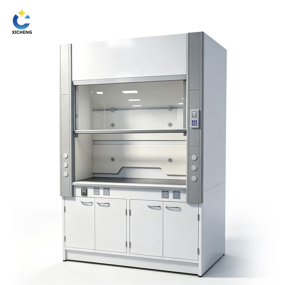
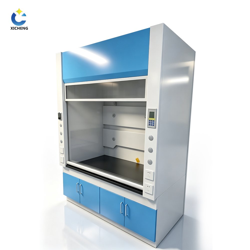
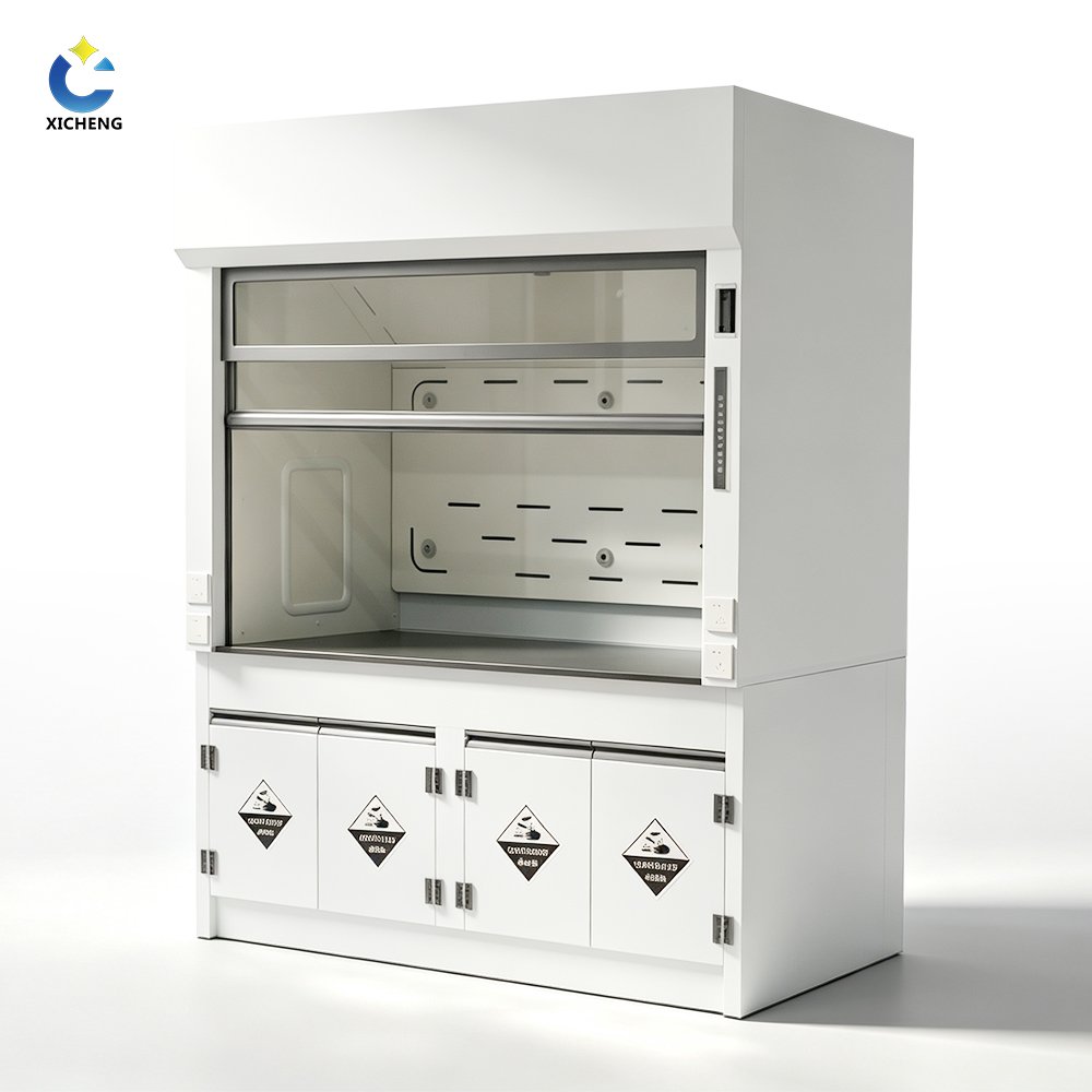
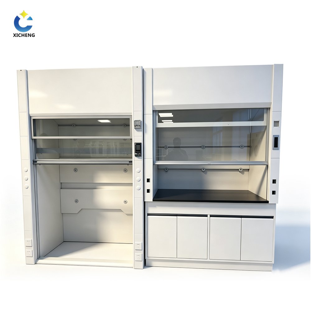
An FRP laboratory fume hood is a local exhaust enclosure that draws room air through the sash opening and carries released vapors toward a duct connection. It supports containment of corrosive fumes, odors, and light airborne contamination generated by normal-temperature laboratory procedures. The hood does not filter or recirculate exhaust air unless separately specified treatment equipment is included in the ventilation system.
FRP means fiberglass reinforced plastic, which is a family of composite materials rather than one fixed resin grade. Glass-fiber reinforcement gives the composite its structure, while the resin matrix and exposed surface layer govern much of its chemical and temperature resistance. The order specification therefore needs to identify both the FRP components and their selected resin system.
Full FRP body versus FRP-lined construction
The name “FRP fume hood” is used for more than one cabinet design. It may describe a hood with an FRP body and work area, an FRP superstructure on a different base cabinet, or a metal outer cabinet fitted with an FRP liner and baffle. These arrangements can expose different materials to the same fumes, splashes, condensate, and cleaning agents.
Before quotation, the material schedule should identify the outer cabinet, inner liner, work surface, baffle, air foil, exhaust collar, base cabinet, drain parts, service fittings, and exposed hardware. This component-level record shows where the selected chemical barrier begins and ends. A generic note such as “FRP construction” does not provide enough information to approve material compatibility.
Hood body and exhaust-system boundary
Containment at the sash is a result of the complete ventilation system. Hood geometry and baffle arrangement direct air inside the enclosure, but the exhaust fan creates the pressure difference that moves air through it. Sash position, duct resistance, fan duty, room make-up air, downstream treatment, and the number of hoods operating together can all change the measured face velocity.
The quotation should state whether the supply stops at the exhaust collar or includes external ductwork, a corrosion-resistant fan, airflow-control valve, VFD, airflow monitor, room-pressure controls, scrubber, or discharge stack. When another contractor supplies any of these items, the interface drawing should define connection material and size, required airflow and static pressure, power and control signals, and commissioning responsibility.
Key features
Composite construction for corrosive laboratory conditions
FRP construction combines glass-fiber reinforcement with a resin matrix, giving the enclosure a rigid composite structure and a selectable chemical barrier. For a laboratory hood, this allows the material schedule to address the cabinet, liner, baffle, work surface, and exhaust interface instead of relying on a general painted-metal finish. The benefit depends on the resin and exposed surface selected for the process.
Compatibility must account for how the chemical reaches each component. Vapor exposure, intermittent splashes, condensed liquid, spills, and cleaning contact can produce different material demands. Review the chemical identity, concentration, temperature, contact duration, and mixture before approving the resin, surface layer, worktop, drain, collar, fasteners, duct, and fan materials.
Built around laboratory layout and services
XICHENG lists floor-mounted reference configurations of 1200 x 800 x 2350 mm, 1500 x 800 x 2350 mm, and 1800 x 800 x 2350 mm. These are external planning dimensions rather than guaranteed internal clearances. The apparatus, sash travel, baffle, service positions, work-surface height, base cabinet, and exhaust-collar location determine the usable work zone in the approved drawing.
Customization may cover the FRP component scope, work surface, sink or cup sink, drain, electrical outlets, water, gas or vacuum fittings, lighting, control panel, airflow monitor, base storage, and exhaust connection. Each selected item should appear on the drawing with its position and applicable standard. Apparatus and service runs should not obstruct baffle openings, sash movement, or maintenance access.
Technical specifications
Confirmed configuration and order-specific items
| Item | Product-family configuration |
|---|---|
| Product type | Floor-mounted laboratory fume hood for connection to a ducted exhaust system |
| Material designation | Fiberglass reinforced plastic; component scope, resin system, reinforcement, laminate, and exposed surface confirmed for the order |
| Primary function | Laboratory exhaust and velocity control for corrosive chemical ventilation |
| Reference external sizes | 1200 x 800 x 2350 mm; 1500 x 800 x 2350 mm; 1800 x 800 x 2350 mm |
| Working condition | Normal temperature; actual chemical and process temperature reviewed before material approval |
| Reference finish | White, smooth-surface, rectangular configuration |
| Planning face velocity | 0.3 to 0.5 m/s at a defined sash position; final target follows the site risk assessment and ventilation design |
| Front sash | Configuration, glazing material, travel, and maximum working opening defined on the approved drawing |
| Work surface | FRP or another material selected against the chemical, temperature, spill, and cleaning schedule |
| Exhaust connection | Collar material, position, diameter, and required static pressure defined for the selected system |
| Controls | Basic switching, airflow monitor, alarm, CAV, or VAV interface as specified |
| Laboratory services | Electrical, water, gas, vacuum, sink, cup sink, and drain provisions as required |
| Customization | Available; final options recorded in the quotation, datasheet, and drawing |
| Certification documentation | CE documentation available; confirm the applicable product scope and order documents before purchase |
| Place of origin | Guangdong, China |
This is a non-standard, made-to-order product family. The resin formulation, laminate and exposed surface, internal dimensions, maximum sash opening, collar diameter, design airflow, electrical load, utility package, controls and accessory scope are selected for the project and fixed in the quotation, technical datasheet and approved drawing before manufacture.
Reference sizes and custom dimensions
Size-selection factors
Begin with the apparatus envelope rather than the nominal hood width. Record the equipment width, depth, height, support frame, loading path, service connections, and access needed for operation and maintenance. The usable work zone will be smaller than the external cabinet dimensions because the sash guides, side walls, baffle, service panels, and structural components occupy space.
Check the delivery route, door and lift openings, ceiling height, final floor level, base clearance, utility entries, and duct route before approving the cabinet size. A wider sash opening creates a larger face area, so maintaining the same face velocity requires more exhaust airflow. Hood width, opening height, fan duty, duct size, and room make-up air therefore need to be reviewed together.
Reference 1200, 1500, and 1800 mm configurations
The dimensions below are common planning configurations, not fixed manufacturing limits. XICHENG can adjust the external envelope, internal work zone, base, sash, work surface, services, access panels, and exhaust connection to the approved apparatus and room layout.
| Nominal width | Reference external size (W x D x H) | Early planning fit |
|---|---|---|
| 1200 mm | 1200 x 800 x 2350 mm | Compact station for smaller apparatus and a limited service layout |
| 1500 mm | 1500 x 800 x 2350 mm | General laboratory procedures requiring moderate working width |
| 1800 mm | 1800 x 800 x 2350 mm | Larger apparatus or additional horizontal working clearance |
Drawing review before ordering
The approved general-arrangement drawing should show the external envelope, usable internal width and height, work-surface elevation, maximum working sash opening, base arrangement, service positions, exhaust-collar location, and installation clearances. It should also identify removable panels, door-swing or panel-removal space, anchoring points, and the route used to bring the assembled or separated sections into the room.
For connection to an existing system, provide the duct material and size, available airflow and static pressure at the proposed connection, fan operating point, control method, and downstream treatment. For a new system, provide the room plan, proposed duct route, simultaneous hood schedule, discharge requirement, and make-up-air strategy. These inputs allow the hood opening, collar, fan, controls, and treatment train to be checked before the drawing is frozen.
FRP construction details
Resin, reinforcement, and surface layer
An FRP panel is a laminate rather than a homogeneous plastic sheet. Reinforcement layers provide stiffness, the resin matrix binds the fibers, and a resin-rich layer or specified finish forms the exposed work surface. Resin chemistry, reinforcement arrangement, cure quality, joints, and surface condition all affect service behavior. Because the hood is made to order, the resin system and laminate construction are selected for the approved chemical, temperature, and mechanical requirements.
The order material schedule should state the resin family and grade, reinforcement method, nominal laminate thickness for each component, chemical-barrier layer, exposed finish, color, joint method, edge treatment, and repair procedure. For critical exposure, request the resin supplier’s compatibility data for the stated chemical and temperature. Any site-cut opening or damaged surface also needs an approved sealing and inspection method.
Work surface, sash, baffle, and hardware
The work surface can receive longer liquid contact than the cabinet walls, so it should be selected separately for spill chemistry, temperature, impact, apparatus load, and cleaning. The drawing should state its material, thickness, raised edge or containment profile, sink or cup sink, drain, cut-outs, joints, and support. A drain provision does not establish permission to discharge laboratory chemicals into the building system.
The sash provides access and a physical barrier, while the baffle and air foil influence how air enters and moves through the enclosure. Specify the glazing material and thickness, sash direction and travel, counterbalance or drive, frame, baffle positions, removable sections, and cleaning access. Handles, guides, hinges, fasteners, gaskets, and service fittings also require material review because they may face vapor or splash exposure.
Chemical and temperature compatibility
Compatibility review requires the exact chemical name, concentration, temperature, physical form, contact duration, frequency, mixture, spill potential, and cleaning agent. Vapor-only contact can differ from pooled liquid or repeated condensate, and condensate may concentrate contaminants in the baffle, collar, drain, duct, or fan. A general resistance chart is a screening tool; final approval should use the selected resin data and the stated exposure conditions.
The XICHENG source identifies normal-temperature use. Elevated heat, perchloric acid, hydrofluoric acid, concentrated oxidizers, solvent-rich or flammable atmospheres, radioactive materials, and processes with heavy condensation need a separate technical review. Some require a dedicated wash-down system, ignition-risk controls, filtration, or a different material construction. A standard FRP hood listing should not be treated as approval for any of these services.
Applications
General corrosive chemical laboratory work
This fiberglass fume hood can be considered for normal-temperature procedures that release corrosive vapors, acid or alkali fumes, odors, or light airborne contamination and require ducted local exhaust. Potential tasks include reagent preparation, sample treatment, liquid transfer, mixing, wet chemistry, and apparatus venting. Each task still needs to fit the selected resin, work-surface material, sash arrangement, and exhaust design.
As a common operating benchmark, place the emission source and apparatus at least 150 mm behind the sash plane when the equipment and approved procedure allow it. Raise bulky equipment where needed to preserve the rear airflow path, keep the sash at its designated working height, limit cross-drafts and nearby traffic, and avoid using the hood as permanent chemical storage. Site procedures and commissioning tests take precedence.
Wet chemistry, analytical, and industrial laboratories
Potential settings include educational, hospital support, research, analytical, quality-control, and industrial laboratories, as well as chemical-plant testing areas. FRP may be evaluated where wet chemistry or corrosive vapor exposure makes a general painted-metal work enclosure unsuitable. The decision still depends on the chemicals, temperature, quantities, apparatus, operating frequency, cleaning method, and required exhaust treatment.
A teaching laboratory using small quantities of dilute reagents, an analytical laboratory handling volatile solvents, and a process laboratory sampling a concentrated or heated stream do not present the same design basis. Vapor chemistry, heat release, batch size, operating frequency, spill potential, fire requirements, and treatment needs can change the enclosure, work surface, services, controls, and exhaust materials. Select from the process schedule, not the room label.
Processes that need a dedicated design
Do not select a standard FRP hood from the category name alone for perchloric acid, hydrofluoric acid, strong oxidizers, high-heat work, flammable-vapor service, radioisotopes, or unusually toxic materials. Submit the process hazard review before configuration. The result may require a different liner or resin, wash-down provisions, dedicated ductwork and fan, filtration, continuous monitoring, fire controls, or another enclosure type.
A chemical fume hood is not a biological safety cabinet, clean bench, glovebox, or simple canopy hood. It draws room air through a front opening and exhausts contaminated air away from the laboratory. It does not provide sterile product protection, an inert atmosphere, or biological containment by default. Processes needing HEPA containment, recirculation, oxygen control, or capture from large open equipment require a purpose-specific system.
Ventilation-system compatibility
Face velocity and containment
Face velocity is the air speed measured through the open sash plane, not the total airflow rating of the fan. It should be assessed over a measurement grid at a stated sash height after the connected system is operating. Average velocity, point-to-point variation, airflow visualization, and response to room disturbances all matter because one acceptable average can conceal weak or turbulent zones.
For preliminary sizing, use airflow = opening width x opening height x face velocity x 3600. At an assumed 600 mm opening and 0.4 m/s face velocity, the calculated airflow is about 1,040 m3/h for a 1200 mm hood, 1,300 m3/h for a 1500 mm hood, and 1,555 m3/h for an 1800 mm hood. These are derived examples, not published XICHENG exhaust volumes or final fan selections.
Hood body versus complete exhaust system
The exhaust collar is only the starting point of the air path. The fan must deliver the required airflow while overcoming losses through the hood, straight duct, elbows, branches, dampers or control valves, transitions, scrubber or filter, silencer, and discharge stack. An airflow estimate without a system-resistance calculation is not enough to select the fan operating point.
The system schedule should state whether the hood, external duct, fan, airflow-control valve, VFD, airflow monitor, room-pressure controller, treatment unit, and discharge stack are included or supplied by others. For each item, record the quantity, material, design duty, power supply, control interface, installation work, wiring, testing, and commissioning responsibility. This keeps equipment selection and contractor handoffs on the same design basis.
Inputs for fan, duct, and treatment selection
Provide the hood width, maximum working opening, target face velocity, duct material, route length, fittings, branch arrangement, simultaneous-operation schedule, fan location, discharge elevation, and treatment-equipment pressure loss. Add the room pressure target, available make-up air, ambient conditions, and any future expansion allowance. These inputs support the airflow calculation, system-resistance model, duct sizing, and fan duty selection.
For CAV control, define the operating setpoint, start and stop sequence, monitor, alarm, and interlock requirements. For VAV control, add the sash signal, minimum and maximum airflow, response behavior, required emergency mode, valve interface, and building-management connection. For a scrubber, provide the contaminants, inlet concentration, airflow, moisture, temperature, removal objective, discharge limit, and waste-liquid arrangement.
Customization options
Work area, utilities, and controls
Start configuration with the apparatus drawing and operating sequence. Mark the loading path, normal working position, required clearances, observation points, maintenance access, and each service connection. Then locate the work-surface cut-outs, sink or cup sink, drain, electrical outlets, water, gas, vacuum, lighting, monitor, and control panel around that workflow rather than adding them after the cabinet layout is fixed.
For each electrical point, state the voltage, frequency, phase, socket standard, connected load, isolation method, and required ingress protection. For each liquid or gas service, state the medium, supply pressure, connection standard, fitting and valve materials, shutoff location, and test requirement. Separate electrical components from wet zones, preserve access to valves and wiring, and show every interface on the service drawing.
FRP duct, fan, and scrubber integration
Material compatibility must continue beyond the hood collar. Review the external duct and joints, gaskets, dampers or airflow valves, fan casing, impeller, shaft protection, flexible connectors, fasteners, scrubber shell and internals, mist eliminator, recirculation piping, and drain. Exhaust composition can change as vapor cools, condenses, mixes with other branches, or contacts scrubbing liquid, so downstream exposure may differ from the work chamber.
The coordinated system drawing should show duct sizes and slopes, supports, condensate drains, inspection access, flexible connections, fan location and isolation, valve and sensor positions, scrubber, pump, make-up water, waste-liquid connection, and discharge stack. The control schematic should identify run permissives, alarms, interlocks, fan or VFD commands, valve response, pump status, and building-management signals for the selected package.
Configuration documentation
Control the configuration through one document register covering the quotation, datasheet, general-arrangement drawing, component material schedule, service drawing, ventilation schedule, electrical schematic, control sequence, accessory list, and packing list. Each document should carry a revision and approval status. Any change after approval should identify the affected dimensions, materials, performance basis, interfaces, price, and delivery schedule before manufacture continues.
Factory inspection can verify dimensions, visible finish, component identity, sash movement, service fit-out, wiring, controls, alarms, labels, and packing against the approved documents. Airflow and containment results are valid only for the stated test arrangement. After installation, site commissioning should verify face velocity, visualization, alarms, interlocks, room interaction, and connected-system operation under the agreed sash and operating conditions.
Selection notes
When FRP is a good fit
FRP is a practical candidate when a normal-temperature laboratory process needs a rigid composite enclosure and the selected resin and surface layer are compatible with the stated vapor, splash, condensate, and cleaning exposure. It is most defensible when the order documents identify every exposed component, the ventilation system is designed for the operating sash, and the site can inspect and maintain the composite surfaces and joints.
Do not select it from the phrase “corrosion resistant” alone. Elevated temperature, strong oxidizers, solvent exposure, fire requirements, heavy impact, frequent field modification, aggressive decontamination, or limited repair capability may change the material decision. Compare the applicable resin data, building and fire requirements, mechanical demands, cleaning method, expected service life, inspection plan, repair method, and replacement strategy before approval.
FRP versus PP and stainless steel
FRP is a reinforced composite whose behavior depends on the resin, fibers, laminate, joints, and surface barrier. PP is a thermoplastic sheet material that can be fabricated with welded joints and selected against its own chemical, temperature, and fire limits. Stainless steel is a metal construction whose grade, finish, welds, and exposure chemistry determine performance. The material family name alone is not a complete specification for any of the three.
Compare all three against the same chemical list, concentration, temperature, physical form, contact duration, cleaning method, fire requirement, contamination limit, mechanical load, impact risk, joint design, inspection method, field-repair capability, expected service life, availability, and replacement cost. Extend the comparison from the hood chamber to the work surface, drain, duct, fan, valves, and treatment equipment that face the exhaust.
Information needed for material selection
Submit the chemical names or safety data sheets, maximum concentrations and temperatures, physical form, quantity per operation, batch frequency, exposure duration, possible mixtures, heat release, apparatus dimensions, cleaning chemicals, and spill scenario. Separate normal operation from startup, shutdown, upset, cleaning, and maintenance conditions because the most severe exposure may occur outside the routine procedure.
Add the room drawing, delivery route, ceiling height, required hood quantity, preferred sizes, simultaneous-operation schedule, proposed duct path, available airflow and static pressure, room-pressure and make-up-air targets, fan and treatment scope, utility standards, electrical supply, applicable code or certification requirement, document language, destination, and packing constraints. These inputs support a configuration proposal and an open-item register for unresolved values.
Packaging and quotation information
Minimum order, warranty, and packing
Orders can start from one customized unit. A one-year warranty and wooden-frame or wooden-box transport packing can be included according to the quoted configuration and destination. The formal quotation confirms the warranty start point, covered components, exclusions, remedy, spare-part handling, and whether customized controls or third-party equipment carry separate terms.
The packing plan should state whether the hood ships assembled or in sections and how the glazing, work surface, controls, service fittings, removable panels, and loose accessories are protected and identified. Confirm package count, dimensions, weight, lifting points, moisture protection, destination labeling, packing-list references, and any destination requirement for wood treatment or certificates before dispatch.
Origin and production schedule
The equipment is manufactured in Guangdong, China. Production timing depends on the approved FRP component scope, resin and surface system, dimensions, work surface, sash, services, controls, exhaust package, order quantity, documentation, and purchased components. A reference external size does not by itself create a fixed lead time when the material schedule and interfaces are customized.
The quotation should separate technical-data submission, drawing review, approval freeze, material procurement, fabrication, inspection, corrective work, packing, dispatch, transit, installation, and commissioning milestones. It should also state the event that starts the production period and how late approvals or scope changes affect the dates. This gives both parties a schedule basis that can be updated without rewriting the product specification.
Information needed for quotation
Provide the required quantity, delivery destination, requested trade term, delivery target, quotation currency, tax or duty responsibility, payment requirement, warranty expectation, installation and commissioning scope, training need, spare-parts request, document language, required certificates, and quotation-validity period. State whether freight, unloading, positioning, utilities, ductwork, fan, controls, and exhaust treatment are to be priced or excluded.
Attach the process schedule, material-selection basis, room drawing, service requirements, and ventilation inputs to the enquiry. The returned quotation should identify the proposed configuration, line-item scope, options, deviations, assumptions, exclusions, unit and total pricing, document deliverables, inspection scope, schedule basis, and unresolved technical items. This prevents a hood-only price from being compared with a coordinated exhaust package as though the scopes were equal.
Datasheet and technical review
Datasheet for the selected configuration
The final datasheet should record a unique product reference, external and usable internal dimensions, FRP component scope, resin and laminate schedule, exposed finish, work surface, sash, baffle, services, electrical supply, controls, exhaust connection, design airflow basis, working conditions, accessories, certification documents, inspection scope, packing, and supply boundary. Each value should match the approved drawings and quotation revision.
Use the datasheet for selected values, the general-arrangement and service drawings for positions and clearances, the material schedule for component construction, the electrical and control documents for wiring and sequence, and the supply schedule for responsibility. Cross-reference the documents by revision. If they conflict, resolve the difference through the agreed document-precedence rule before fabrication or site connection.
Unconfirmed values that must remain open
The available XICHENG source does not confirm an FRP-specific model number, resin grade, laminate thickness, reinforcement schedule, internal dimensions, sash material or maximum opening, exhaust-collar size, published air volume, pressure loss, noise, electrical load, product weight, load capacity, standard services, or included exhaust equipment. Keep these values out of fixed product claims until an approved XICHENG datasheet or drawing supports them.
If a required value is not shown in the current specification, request it for the selected configuration rather than applying a generic industry value. Dimensions, airflow conditions, material scope, component options and control interfaces should agree across the quotation, approved drawing, visible specification and Product schema before the product is released for manufacture.
Optional Fume Hood Airflow and Sash Control Integration
The FRP fume hood can be supplied with coordinated sash sensing, a local controller, an airflow-control valve, exhaust-fan control and room-air integration for either CAV or VAV operation. These components are optional project scope and must be identified separately from the composite hood body. The control package supports operation, but verified containment still depends on the installed exhaust system, room conditions and final commissioning.
Choose CAV or VAV from the Operating Requirement
A CAV arrangement holds one scheduled exhaust airflow at the approved sash condition, whereas a VAV arrangement changes exhaust demand from sash position or measured face velocity. The selected control valve must provide the required response across the approved operating range. For corrosive exhaust, choose the control method together with the valve-body, sensor-pickup, tubing, shaft and seal materials; the FRP hood shell does not automatically make those separate components chemically suitable.
For a Venturi mechanism, compare the VAV Venturi Air Valve or CAV Venturi Air Valve. A rotating-blade solution can use the VAV Butterfly damper. Each valve still needs its own size, pressure, material, sensor, actuator and commissioning schedule.
Local Controller, Display, Alarm and Emergency Functions
A compatible controller and local panel can present operating values, receive sash-position or face-velocity signals, issue audible and visual alarms, and support an emergency exhaust command. Define the measured variable, engineering units, alarm limits, delay, acknowledgement, emergency sequence and BMS interface before approval. Sensor range, calibration access and acceptance testing must also be stated, particularly where tubing or penetrations pass through the composite construction.
Automatic Sash Control and Safety Inputs
An optional automatic sash-control system is shown with a control panel, controller, reel-type displacement sensor, anti-pinch hand sensor, synchronized drive and personnel detection. The controller supports manual, follow and energy-saving modes and can accept presence, foot-switch and anti-pinch inputs according to configuration. The project must define movement limits, obstruction response, manual release, loss-of-power behavior and periodic safety testing. Automatic movement does not replace the hood operating procedure or airflow alarm.
Room Supply, Exhaust Tracking and System Boundary
The hood exhaust command affects room air balance. Where several hoods or other exhaust devices operate together, coordinate the valve signal with room supply, general exhaust and the target pressure relationship. The room controller, sensors, valve actuators, fan/VFD logic, BMS points and final testing remain separate scope unless the quotation lists them.
For an FRP hood, review how sensor fittings, sash hardware, cables and valve connections pass through or attach to the composite construction. The FRP body does not establish the resin, corrosion resistance or fire behavior of separate control components.
For a project-ready control quotation, provide hood width, maximum working sash opening, target face velocity or airflow modes, valve location and available pressure, room supply/exhaust schedule, fan/VFD arrangement, sash-control requirement, alarm and emergency sequence, BMS protocol, point list and failure behavior. The returned proposal should identify every supplied sensor, controller, display, valve, actuator, cable and field responsibility.
Related products
Laboratory control and exhaust components
An FRP fume hood may be coordinated with laboratory airflow-control products, laboratory control systems, and laboratory ventilation components. Depending on the project, the connected system may include a valve or damper, actuator, airflow monitor, VFD, room-pressure controller, corrosion-resistant duct and fan, exhaust treatment, and a discharge stack.
Select the connected products from one airflow and chemical basis. Share the design airflow, system static pressure, exhaust composition, temperature, moisture, room-pressure strategy, simultaneous-operation schedule, control sequence, alarm requirements, discharge objective, and treatment target across the hood, controls, duct, fan, and treatment equipment. Confirm each interface and supplier responsibility before ordering separate packages.
Related fume hood materials
Compare this configuration with the PP laboratory fume hood when welded thermoplastic construction is under consideration, and with the stainless steel fume hood when a specified metal grade and finish are being evaluated. These pages describe different material routes; neither material name replaces a chemical, thermal, fire, mechanical, and cleaning review.
The laboratory fume hood category groups the current material options. Build the shortlist from one process brief and compare each option in the same matrix: confirmed construction, open values, chemical and temperature basis, external and internal dimensions, airflow basis, utilities, controls, system scope, documentation, price, and delivery. Record deviations instead of treating blank fields as equivalent.
FAQ
What is an FRP laboratory fume hood used for?
It provides ducted local exhaust for normal-temperature laboratory procedures that release corrosive vapors, acid or alkali fumes, odors, or light airborne contamination. Common candidate tasks include reagent preparation, liquid transfer, sample treatment, wet chemistry, and apparatus venting. The selected resin, exposed components, sash arrangement, and connected exhaust system must still be approved for the actual process.
Is FRP the same as fiberglass reinforced polyester?
No. FRP means fiberglass reinforced plastic and covers a broader family of composites. Fiberglass reinforced polyester is one type within that family; other FRP systems can use vinyl ester, epoxy, or another resin. The names are not interchangeable because resin chemistry affects chemical and temperature behavior. The resin system is selected from the submitted chemical and temperature schedule and identified in the order specification.
Is the complete hood made from FRP or only the liner?
Either arrangement is possible because this product is configured for the project, and the term “FRP fume hood” does not by itself define the component scope. The approved material schedule identifies the outer cabinet, inner liner, baffle, work surface, air foil, collar, base cabinet, drain, service fittings, and exposed hardware before chemical compatibility is approved.
Is FRP suitable for every acid, alkali, or solvent?
No. Compatibility depends on the resin and surface layer, chemical identity, concentration, temperature, contact time, physical form, mixture, and cleaning method. Vapor exposure can differ from a spill or repeated condensate. Strong oxidizers, solvent-rich mixtures, elevated heat, and special acids may require another resin, another construction, or a dedicated system. Approve the selected materials against the actual exposure schedule.
What sizes are available?
Common external planning sizes are 1200 x 800 x 2350 mm, 1500 x 800 x 2350 mm, and 1800 x 800 x 2350 mm. Custom dimensions are available. Confirm the internal width and height, work-surface elevation, maximum sash opening, base arrangement, services, exhaust collar, access route, and installation clearances on the approved drawing.
What face velocity and exhaust volume are required?
A preliminary face-velocity range of 0.3 to 0.5 m/s at a defined sash position can support early planning. Calculate exhaust volume from the open sash width, opening height, and target velocity. Because the hood is configured for the project, final airflow depends on the risk assessment, hood geometry, measurement method, room air, duct resistance, simultaneous operation, treatment equipment, and site standard.
Can the hood be customized?
Yes. The selected configuration may address external dimensions, FRP component scope, resin and finish, work surface, sash, sinks and drains, utilities, electrical standards, lighting, controls, monitoring, base storage, exhaust connection, branding, and packing. An option becomes part of the product only when it appears in the quotation, datasheet, and approved drawing.
Are the fan, ductwork, and scrubber included?
Only when they are listed in the quoted supply scope. The hood may be supplied for connection to equipment by others or coordinated with ductwork, a corrosion-resistant fan, airflow controls, VFD control, room-pressure control, and exhaust treatment. Package selection requires the design airflow, system resistance, exhaust composition, duct route, room conditions, discharge objective, control sequence, and clear installation and commissioning responsibilities.
Contact the Xicheng Engineering Team Today.
Send us your process chemicals and concentrations, operating temperature, preferred fume hood size, target face velocity, required utilities, and laboratory layout or CAD drawings. Our engineers will prepare a material-specific fume hood configuration, exhaust-system integration proposal, and quotation within 24 hours.
🎯 Shenzhen Office: No. 34 Zhenxing Road (Shengtaian Heavy Industrial Park B), Loucun, Guangming New District, Shenzhen, Guangdong, China
☎️ WhatsApp: +86 181 2647 8161
📬 Engineering Mailbox: fanalax34@gmail.com