


Description
Constant Volume Venturi Air Valve for Fixed Laboratory Airflow
A constant volume Venturi air valve maintains one scheduled airflow setting while differential pressure changes across the valve. The shaped body and internal cone/spring assembly provide passive pressure compensation inside the selected operating envelope. The base configuration is mechanical and does not require power to hold its fixed setting.
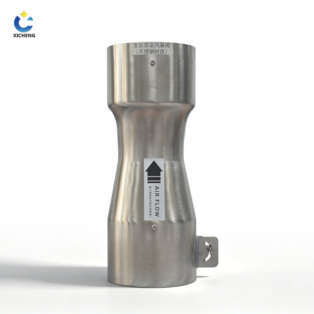
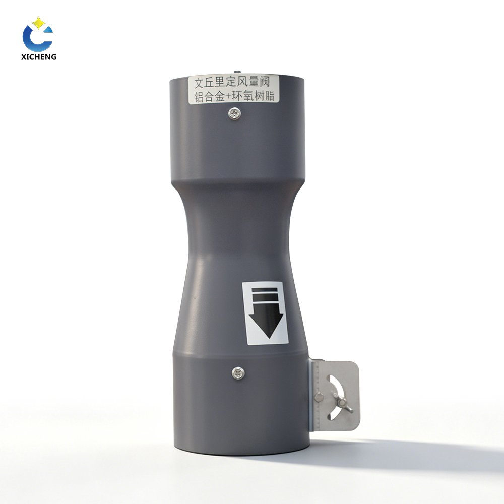
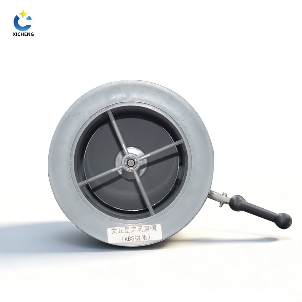
XICHENG supplies ABS, aluminum alloy and stainless steel configurations for laboratory supply, general exhaust and dedicated equipment branches. Single bodies and parallel arrangements are available. The product is selected from the required fixed airflow, available differential pressure, material exposure and installation geometry.
What the Base CAV Valve Includes
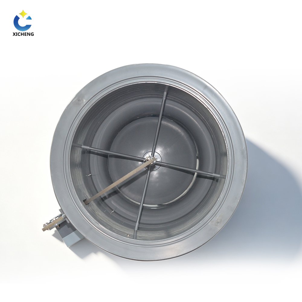
The base assembly includes the Venturi body, internal cone and spring mechanism, and the mechanical setting arrangement. The scheduled airflow is established for the selected body and operating range. Optional position indication or monitoring can be evaluated separately, but it does not change the product into an actively modulating VAV valve.
The quotation should identify material, size, airflow setting, pressure range, orientation, connection and multi-body arrangement. Where an electrical accessory is requested, list its purpose, signal, power and supplied scope rather than assuming it is part of the mechanical base product.
This separation is useful during procurement. A mechanical CAV valve can remain functional without a network, but a project may still need an airflow alarm or status point. Listing that monitoring package separately makes the valve’s passive airflow duty clear and prevents an optional sensor from being mistaken for the component that maintains the flow.
Choose This Product When
- The branch requires one constant airflow during its normal operating mode.
- The available differential pressure remains within the selected valve’s 150-750 Pa family envelope.
- A mechanical setting is preferred over an active VAV controller and actuator.
- ABS, aluminum or stainless construction can be matched to the air stream.
- The setting and actual installed airflow will be verified during commissioning.
Typical uses include constant laboratory supply, general exhaust, equipment exhaust and branches that operate whenever a fan or process is enabled. A branch with several distinct airflow targets should be evaluated as VAV or two-position control instead.
For an exhaust branch, the fixed setpoint should reflect the process requirement and the air needed to maintain the intended room balance. For a supply branch, confirm that the constant flow remains appropriate as other room exhaust devices change. The room controller may need to coordinate another variable branch even when this valve itself remains constant.
When a Fixed CAV Setting Is Not Enough
A fume hood with changing sash demand, a room with occupied/unoccupied airflow reset, or a branch requiring normal and emergency flow needs more than one fixed setting. Use the VAV Venturi Air Valve when the command must change continuously, or the Two-Position Constant Air Volume Damper when two discrete operating states are sufficient.
The CAV valve is not a fire, smoke, blast, backdraft or certified isolation device. No universal leakage class, BMS function or fail-safe electrical behavior is assigned to the mechanical base configuration.
Key Performance, Sizes and Fixed Airflow Ranges
The values below describe available constant-volume configurations. Accuracy and airflow range apply only when the selected body and fixed setting operate within the stated pressure conditions. Final values belong on the valve schedule and approved submittal.
Family Performance References
| Specification | Available Configuration |
|---|---|
| Working differential pressure | 150-750 Pa |
| Airflow-control accuracy | No more than +/-5% within the stated operating range |
| Materials | ABS, aluminum alloy, stainless steel 304/316 and selected coated configuration |
| Base control mode | Mechanically fixed CAV airflow setting |
| Power requirement | No power required to hold the base mechanical CAV setting |
| Family selection range | 80-10,000 CMH using single or combined-valve arrangements |
The accuracy statement remains tied to the selected range and operating pressure. The 10,000 CMH upper value requires an applicable combined-body arrangement and must not be assigned to one valve. The base CAV product does not need an actuator or communication network to hold its fixed mechanical setting.
Use these figures as selection boundaries, not as unconditional guarantees detached from the approved schedule. The final schedule should repeat the applicable pressure range and fixed airflow beside each tag. Optional position indication or monitoring must be identified separately from the mechanical airflow-setting function.
ABS Body Sizes
| ABS Size | D1 | D2 | Overall Length | Published Airflow Range |
|---|---|---|---|---|
| 110 | 165 mm | 102 mm | 482 mm | 80-350 CMH |
| 160 | 215 mm | 150 mm | 455 mm | 100-700 CMH |
| 200 | 257 mm | 190 mm | 578 mm | 150-1,600 CMH |
| 250 | 330 mm | 248 mm | 662 mm | 250-1,800 CMH |
| 250 compact | 330 mm | 248 mm | 532 mm | 250-1,500 CMH |
| 315 | 365 mm | 302/297 mm | 641 mm | 300-2,000 CMH |
| 355 | 435 mm | 352 mm | 765 mm | 300-2,500 CMH |
Aluminum Alloy Body Sizes
| Aluminum Size | OD | ID | Overall Length | Published Airflow Range |
|---|---|---|---|---|
| DN100 | 99.5 mm | 96.5 mm | 270 mm | 20-220 CMH |
| DN150 | 149.5 mm | 146.5 mm | 390 mm | 50-500 CMH |
| DN200 | 199.4 mm | 196.4 mm | 503 mm | 80-1,100 CMH |
| DN250 | 249.2 mm | 246.2 mm | 553 mm | 120-1,600 CMH |
| DN300 | 299.4 mm | 296.4 mm | 683 mm | 160-2,000 CMH |
| DN350 | 353.2 mm | 350.2 mm | 755 mm | 200-2,500 CMH |
ABS and aluminum dimensions use different conventions and cannot be mixed. Stainless steel 304/316 dimensions, coating scope and airflow range are returned on the project drawing. An aluminum value below the 80 CMH family selection statement also requires confirmation of the body, pressure and characterized setpoint range.
Check connection geometry as carefully as airflow. The external diameter, internal diameter and overall length affect transitions, supports and actuator access. A body that covers the airflow range may still be unsuitable if the installed envelope conflicts with adjacent equipment or leaves no service clearance.
Single and Multi-Valve Selection
Use one body when its published range covers every required operating mode. Dual, triple and four-body assemblies extend capacity when one body is insufficient. The combined schedule must identify individual body size and range, total minimum and maximum airflow, common connection, actuator strategy and the method used to combine feedback.

Each body in a fixed CAV assembly receives its own approved setting. The total branch airflow is the sum of the individual bodies, so commissioning must verify every body and the combined result. The project drawing should show body spacing, structural support, access to the setting mechanism and a common transition that distributes airflow across the arrangement.
Materials and Fixed-Setpoint Venturi Principle
The cone and spring react to differential pressure through the Venturi body. As system pressure changes, the mechanism moves to help maintain the airflow associated with the mechanical setting. This compensation works within the selected valve’s characterized pressure and airflow range; it does not make the valve immune to incorrect sizing, blockage or insufficient fan pressure.
How Mechanical CAV Operation Works
The airflow setting establishes the target for one operating condition. Once set and commissioned, the base valve does not require a continuous electrical command to hold that setting. Pressure changes are handled by passive mechanical movement rather than an active control loop.
The 150-750 Pa reference is therefore a real selection boundary. Below the required differential pressure, the valve may not achieve its scheduled airflow. Above the selected envelope, energy, noise and mechanism behavior require review. Fan and duct design must place the valve inside its usable range.
The scheduled airflow is also tied to the selected body and mechanism setting. Moving the setting after commissioning changes the product duty and should trigger a new airflow verification. A marking or setting record should remain with the valve schedule so future maintenance can distinguish an approved adjustment from accidental movement.
ABS for Non-Metallic Construction
The ABS family uses a one-piece molded, flame-retardant body. Its published gas-temperature statement is below 60 C, but final suitability also depends on chemical composition, concentration, humidity, condensate and upset temperature. V0 language belongs to the documented ABS body and should not be generalized to the complete system.
Use the ABS table directly for dimensions and airflow range. The compact 250 version has a shorter body and a lower upper airflow value than the standard 250, so layout benefit and performance must be checked together.
Aluminum Alloy Construction
The aluminum family uses a spun one-piece body with an epoxy coating and an optional fluorocarbon coating where required. The documented configuration includes stainless and coated internal components. Final coating and exposed-component compatibility must be reviewed against the actual air stream.
Aluminum uses its own OD, ID, height and length convention. Do not substitute ABS dimensions or assume the same nominal-size envelope.
Stainless Steel and Coating Selection
Stainless steel 304 and 316 options are available, including a fluorocarbon-coated configuration for selected corrosion duty. Choose the grade and coating from the process chemicals, cleaning method and environmental exposure. Stainless dimensions and flow range must be returned on the approved project drawing rather than copied from aluminum.
The material schedule should list the body, cone, spring, rod, supports, fasteners, seals and coating coverage. A corrosion-resistant outer body alone does not qualify every internal or external component.
Temperature and chemistry should be reviewed together. A polymer that is acceptable at room temperature may have a different limit under warm, concentrated or condensing exposure. Coatings also need inspection criteria because damage at edges, fasteners or moving interfaces can affect long-term service.
Fixed Airflow Setting, Monitoring and System Boundary
The CAV setting is a procurement and commissioning value, not a generic label. Each valve tag should carry one scheduled airflow and its applicable pressure range. For a combined assembly, each body has an individual setting and the branch total is the sum of those values.
Setting the Required Airflow
Start with the operating condition that requires constant airflow. Select a body whose characterized range contains the target without forcing the setting to an unverified endpoint. Confirm connection size, orientation and available pressure, then establish the mechanical setting according to the approved schedule.
After installation, measure actual airflow with the approved reference method. Record the final setting and measured result. If the branch pressure is outside the valve envelope, correct the system condition rather than forcing an unsupported mechanical adjustment.
Commissioning should check more than one system pressure where practical. A fixed setting that appears correct at one fan speed may reveal insufficient available pressure at another operating mode. The result should demonstrate that the passive mechanism has enough authority across the expected pressure variation.
Optional Indication and Monitoring
A project may request a position indication, airflow monitor or BMS alarm. These options require their own sensor, signal, power and point-list definition. They monitor the fixed-flow branch; they do not create active VAV control unless an actuator and controller are explicitly added.
Specify what the feedback represents and how it is scaled. A mechanical position is not automatically an airflow measurement, and an alarm contact does not provide a continuous airflow value.
What the Wider System Still Provides
The valve does not provide the fan, duct system, room pressure controller, fume hood controller, exhaust treatment or building automation platform. A constant branch can contribute to a room balance, but the room pressure result depends on all supply, exhaust and transfer-air paths.
If changing room or hood demand requires the branch airflow to reset, the control strategy should move to VAV rather than repeatedly treating the mechanical CAV valve as an adjustable control device.
Failure and Alarm Planning
The passive base valve does not have an electrical fail position. System response after fan failure, duct blockage or loss of optional monitoring belongs in the wider control narrative. Define how loss of airflow is detected and what equipment or operator action follows.
Where a process requires automatic emergency increase or decrease, the base CAV valve is the wrong control element unless a separate, documented actuation arrangement is added. That requirement should be resolved during selection rather than left to a field modification.
Applications, CAV/VAV Comparison and Selection
A constant volume Venturi air valve is appropriate when one airflow value should remain stable despite ordinary pressure variation. The product is commonly evaluated for laboratory supply, general exhaust and equipment branches with a fixed operating duty.
Suitable Fixed-Airflow Applications
Examples include a constant make-up air branch, a general exhaust branch that operates whenever the room is occupied, or equipment exhaust with one required flow. The pressure-compensating mechanism can reduce the effect of fan or system pressure changes while the branch remains inside the selected range.
A fixed-flow branch can also simplify controls when the process duty is stable and energy reset provides little benefit. The decision should be based on operating modes, not on the assumption that every laboratory branch must be variable. Simpler control is valuable only when the fixed airflow remains safe and compatible with room balance throughout operation.
Process exhaust requires a full material review. Deposits, condensate and particulates can affect the internal mechanism and require inspection access. High temperature, fire, smoke, blast and certified shutoff applications need separate products and evidence.
CAV vs VAV vs Mechanical Airflow Regulator
CAV holds one airflow setting. VAV changes its setpoint under an active command. A Constant Airflow Regulator can also maintain a fixed branch flow but uses a different compact regulator mechanism and has its own size and pressure limitations.
Choose CAV Venturi when the specified Venturi mechanism, material options and single/multi-body range fit the fixed-flow duty. Choose VAV when the process requires changing demand, and compare the mechanical regulator when a simpler duct product can satisfy the branch.
Selection Workflow
- Confirm that the branch truly has one airflow target.
- Provide the target CMH and available differential pressure in all relevant fan modes.
- Select a single body or multi-body arrangement with usable range around the target.
- Choose ABS, aluminum or stainless steel from process and cleaning conditions.
- Confirm dimensions, orientation, connections, supports and access.
- Define any monitoring or alarm separately from the mechanical setting.
- Approve the returned schedule, drawing and commissioning method.
Avoid continuous operation at an extreme endpoint where practical. Selection margin supports balancing, measurement tolerance and future adjustment. Multi-body systems should use body settings that can be verified individually.
For a combined assembly, divide the target airflow into practical individual settings and confirm how air reaches each body. Equal nominal bodies do not guarantee equal airflow if the common transition is poor. The drawing and commissioning plan should address distribution, access and the method for measuring each path.
Project-Ready RFQ Inputs
Send the valve tags, fixed airflow, available pressure, duct size and connection, installation direction and available space. Add air-stream chemistry, temperature, humidity, condensate, cleaning method and preferred material. Identify optional indication, monitoring or alarms and provide the required signal and BMS interface.
The quotation should return body size, material, setting, applicable airflow/pressure range, dimensional drawing, multi-body arrangement, optional accessories, commissioning boundary and commercial terms.
When optional monitoring is required, request the sensor range, output, accuracy basis, power and alarm logic. This prevents a later controls submittal from assigning unsupported functionality to the passive valve body.
Installation, Commissioning and Maintenance
Mechanical pressure compensation depends on the correct valve, orientation and operating pressure. Installation and commissioning should verify the body, setting and branch condition instead of assuming that a nominal size will automatically deliver the scheduled airflow.
Mechanical Installation
Install the valve in the approved airflow direction and orientation. Support the duct independently, align the connections and leave access to the setting mechanism and internal assembly. For multi-body arrangements, use the approved common transition and support frame so each body receives a stable flow path.
Protect the mechanism from construction debris. Confirm tag identification and setting before closing ceilings or service chases. Where the project drawing defines straight runs or transition geometry, preserve those conditions.
Do not use the valve body as a lifting point or duct support. Check that the setting handle or adjustment mechanism remains reachable after insulation, cladding and neighboring services are installed. Multi-body frames need enough clearance to inspect every valve, not only the outer body.
Airflow Setting and Verification
Confirm the fan system is operating in the intended mode and measure the differential pressure across the selected valve. Establish or verify the mechanical setting, then measure actual branch airflow using the approved reference method. Repeat the check at relevant fan or system pressure conditions.
For parallel bodies, verify each body before accepting the combined total. A correct total can conceal one incorrect setting and reduce available capacity or stability. Record the final individual settings and total result.
System Acceptance
Confirm that the constant branch supports the intended room or equipment condition. For room balance, observe supply, exhaust and room pressure with doors and adjacent equipment in representative states. If the application demands a different airflow in another mode, document that gap and use an appropriate VAV or two-position product.
Optional monitoring should be tested independently. Verify sensor scaling, alarm thresholds, BMS points and response to loss of airflow. Monitoring does not alter the mechanical airflow setting unless the supplied package explicitly includes active control.
Inspection and Maintenance
Inspect the body, cone, spring/mechanical components, setting mechanism and connections. Process exhaust may require more frequent checks for buildup, corrosion or restricted movement. Isolate the system and use a material-compatible cleaning procedure.
If airflow changes, compare setting, independent airflow, differential pressure, fan mode and duct condition. A valve cannot maintain the target outside its available pressure range or when the body is obstructed. Diagnose those conditions before changing the setting.
After maintenance, return the mechanism to the recorded setting and repeat the airflow check. If parts are replaced or coating is repaired, document the work against the valve tag so the material and performance history remains traceable.
Related Laboratory Airflow Products
Use the VAV Venturi Air Valve for actively changing setpoints, the Fume Hood Venturi Air Valve for a dedicated hood-control package, or the Constant Airflow Regulator for a different compact mechanical CAV mechanism. Browse all Venturi Air Valves and Laboratory Air Valves & Dampers.
Frequently Asked Questions
Does a Mechanical CAV Venturi Valve Need Power?
No power is required to hold the base fixed mechanical setting. Optional monitoring or electrical accessories may require power and must be listed separately.
What Does Pressure Independent Mean?
The cone/spring mechanism compensates for pressure changes within the selected operating envelope. The valve still needs adequate pressure, correct sizing and commissioning.
Can the Airflow Setting Change During Operation?
The base CAV configuration is intended for one fixed setting. Use a VAV or two-position product when the system requires commanded airflow changes.
Which Materials Are Available?
ABS, aluminum alloy and stainless steel 304/316 configurations are available, with selected coating options. Final suitability depends on the complete air-stream exposure.
Can Multiple Bodies Be Combined?
Yes. Dual, triple and four-body arrangements extend capacity. Each body needs an approved setting, and both individual and total airflow must be verified.
Does the Valve Provide BMS Feedback?
Not as a universal base feature. Position indication, airflow monitoring or alarm signals require a defined optional package with its own power, signal and point list.
Contact the Xicheng Engineering Team Today
Send the fixed airflow target, available differential pressure, preferred material, duct layout and any monitoring requirements. XICHENG will return a body or multi-body selection, setting schedule, dimensional information and quotation.
Shenzhen Office: No. 34 Zhenxing Road (Shengtaian Heavy Industrial Park B), Loucun, Guangming New Dist, Shenzhen, Guangdong, China
WhatsApp: +86 18126478161
Engineering Mailbox: fanalax34@gmail.com