


Description
Motorized air volume control air-air damper selection Summary
This family is intended for projects that need commanded blade movement for branch airflow adjustment, equipment interlock or operating-mode changes. It is a motorized rotating-blade air damper, not automatically a measured-airflow VAV valve or a mechanically pressure-independent device.
Choose This Product Family When
- The duct requires remote on/off or modulating blade movement.
- The body material and connection can be selected from a documented catalog family.
- The project can define actuator supply, command, feedback, travel time and failure behavior.
- Airflow performance will be verified in the installed duct rather than inferred from actuator position.
Published Body Families
| Material / Body Family | Connection | Published Diameter | Catalog Color |
|---|---|---|---|
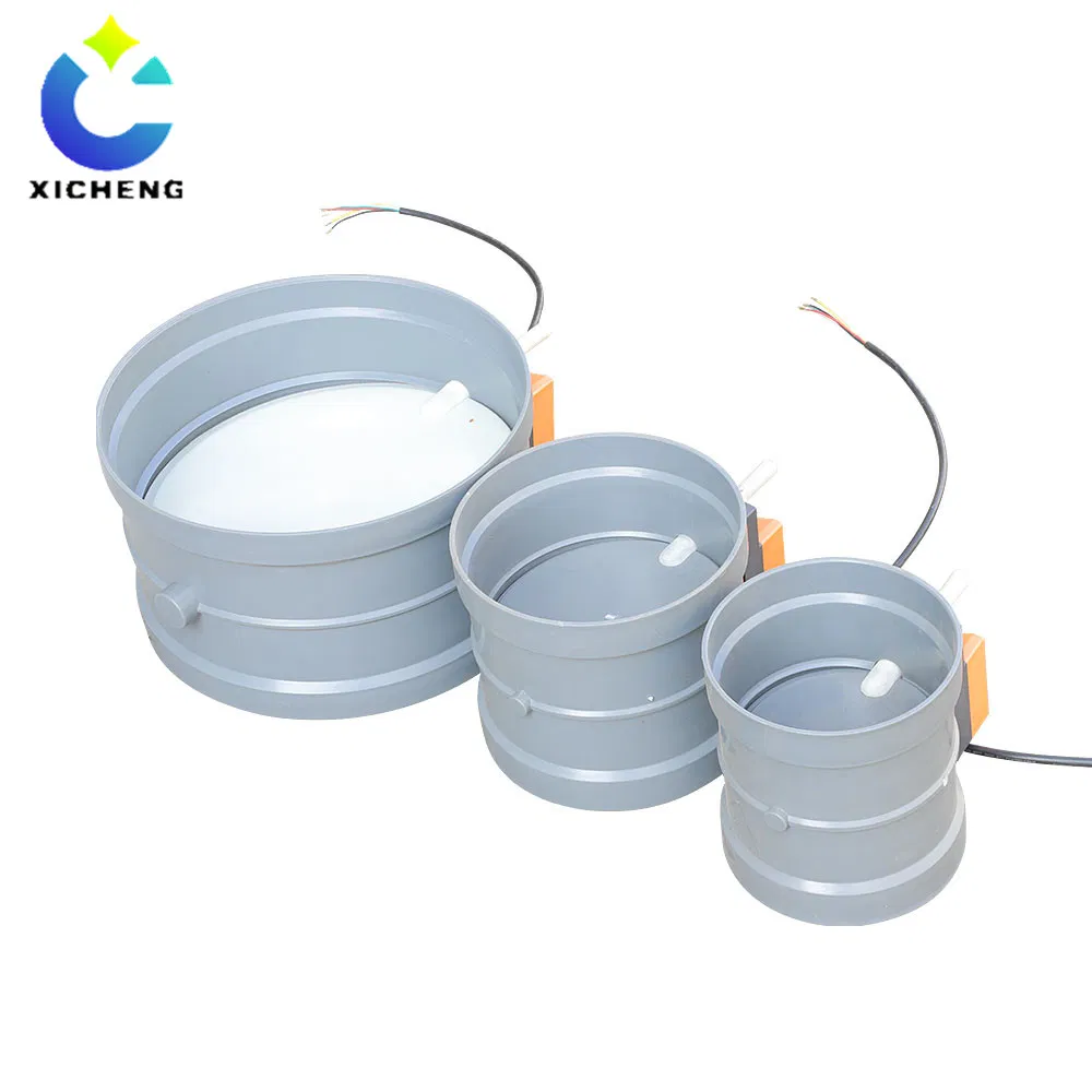
| Flame-retardant PP | Socket | 50-90 mm | Beige or dark gray |
| Flame-retardant PP | Socket | 110-315 mm | Beige or dark gray |
| PP | Socket | 63-315 mm | White |
| PVC | Socket | 63-315 mm | Dark gray |
| Flame-retardant PP | Socket or flange | 160-315 mm | Beige or dark gray |
| Flame-retardant PP or PVC sealed body | Socket or flange | 110-315 mm | By selected material |
| PVC | Socket or flange | 160-315 mm | Transparent |
| Acrylic | Socket or flange | 250 or 315 mm | Transparent |
The catalog also identifies custom round and rectangular bodies in flame-retardant PP, galvanized steel and stainless steel. Their dimensions and actuator package are project-specific.
Controls Boundary
Motorization only establishes electric blade movement. Measured airflow, closed-loop control, Modbus communication, fast response or a specific accuracy requires the corresponding sensor/controller package. The quotation must state which functions are supplied.
Information Required for Quotation
Provide the tag, airflow modes, available pressure, duct shape and dimensions, body material, connection, air-stream conditions, orientation, actuator power, command, feedback, fail position, required travel time, quantity and controls schematic. The approved schedule defines the final non-standard assembly.
Key Specifications
| Specification | PDF-Confirmed Family Data | Project Confirmation |
|---|---|---|
| Product type | Motorized air volume control damper | On/off, positioning or modulating duty |
| Mechanism | Electric actuator drives a rotating blade | Blade, shaft, torque and travel |
| Round body materials | PP, flame-retardant PP, PVC and acrylic | Component-level compatibility |
| Custom body materials | Flame-retardant PP, galvanized steel and stainless steel | Round or rectangular drawing |
| Connections | Socket, flange and sealed-body families | Actual mating dimensions and joint scope |
| Published diameter coverage | 50-315 mm across separate material/connection families | Use only the applicable family row |
| Actuator supply | Selected actuator dependent; catalog actuator family includes AC/DC 24 V | Voltage, circuit capacity and wiring |
| Command and feedback | Defined by selected actuator/control package | Signal range, direction and point list |
| Airflow measurement | Not inherent to a standard motorized damper | Specify sensor/controller separately if required |
| Final performance | Made to order | Approved air damper-tag schedule governs |
Do Not Combine Separate Options
A diameter, material, connection and actuator specification must come from one buildable configuration. Do not combine the acrylic diameter row, sealed PP/PVC connection and an unrelated actuator rating into a single assumed product.
Required Order-Specific Fields
Add body length, connection dimensions, blade and shaft materials, actuator torque, power, command, feedback, travel time, fail position, enclosure, orientation, pressure condition and any leakage requirement to the final schedule.
Motorized damper Operating Principle
How the Actuator Changes Duct Resistance
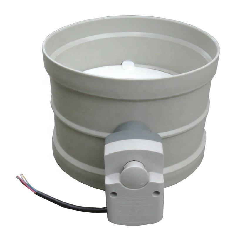
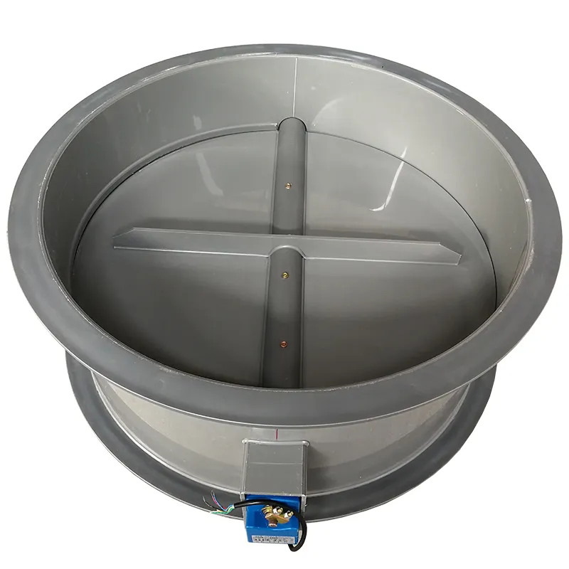
The motorized air volume control damper uses an electric actuator to rotate a blade inside the duct body. As the blade moves toward the open position, it presents less obstruction to the air stream. As it moves toward the closed position, local resistance increases and the branch airflow normally decreases at the current fan and system operating point.
The actuator supplies movement and holding force; it does not create airflow. The fan, duct geometry, fittings, filters, scrubber, terminals and positions of other air dampers determine the pressure available at this branch. A air damper can redistribute or restrict available airflow, but it cannot correct an undersized fan or an exhaust network whose total resistance is higher than the design allowance.
On/Off and Modulating Control Are Different Duties
An on/off duty commands the blade between defined end positions. It may be used to enable or disable a branch as part of an equipment sequence, provided the selected construction meets the required shutoff duty. A modulating duty sends the blade to intermediate positions. It requires a compatible actuator, command signal and commissioning method, and may also require position feedback.
The page does not assume one universal signal protocol. The electrical schedule should state whether the project uses dry contact, a proportional analog signal, a controller output or another interface, then identify the required feedback and fail behavior. XICHENG can match the actuator and control package to that schedule rather than supplying a motor that cannot communicate with the installed system.
Why Blade Position Does Not Prove Airflow
A 50% command means that the actuator has moved toward a scheduled position; it does not mean that the duct carries 50% of design airflow. Butterfly-blade flow response is nonlinear, and the actual result changes as branch pressure and system resistance change. Two equal air dampers at the same blade angle can carry different airflows in different branches.
When the operating requirement is a measured airflow, the system needs a defined sensor location, controller logic and field acceptance method. The PP/PVC motorized air volume control damper can serve as the final control element in that wider loop, but the quotation must identify which sensing and control components are included. A project that requires pressure-independent behavior should instead evaluate a documented VAV Venturi air valve or CAV Venturi air valve.
Material Options by Body Family
The PDF distinguishes standard PP, flame-retardant PP, PVC, transparent PVC, acrylic and custom metal bodies. Chemical suitability still depends on every exposed component and the actual temperature, concentration, condensate and cleaning conditions.
PP and Flame-Retardant PP
Standard white PP socket bodies are published from 63 to 315 mm. Flame-retardant PP appears in separate 50-90 mm and 110-315 mm socket groups, a 160-315 mm socket/flange group, and a 110-315 mm sealed-body group. Confirm the applicable family, color and connection on the quotation.
PVC and Acrylic
Dark-gray PVC socket bodies are published from 63 to 315 mm. Transparent PVC socket/flange bodies are published from 160 to 315 mm, while transparent acrylic socket/flange bodies are listed at 250 and 315 mm. These transparent families should not be generalized to all sizes.
Custom Flame-Retardant PP and Metal Bodies
The catalog identifies non-standard round and rectangular bodies in flame-retardant PP, galvanized steel and stainless steel. Final dimensions, grade or coating, blade/shaft materials, reinforcement and actuator mounting must be defined by the project drawing.
Sizes, Connections and Custom Construction
Use the Material-Specific Diameter Rows
The published round-body families span 50 to 315 mm, but no single material and connection covers every value in that span. Select the applicable row from the front-page family table, then confirm actual mating dimensions, body length, blade clearance and actuator envelope.
Socket, Flange and Sealed-Body Connections
The catalog lists socket, flange and sealed-body constructions. The approved drawing must show outside/inside diameter, insertion depth or flange geometry, wall thickness, gasket or joint method, and the boundary between factory-supplied and field work.
Custom Round and Rectangular Bodies
Non-standard round and rectangular flame-retardant PP, galvanized-steel and stainless-steel air dampers are available by drawing. Their size, reinforcement, blade/shaft construction and actuator torque cannot be inferred from the molded round families.
Coordinate Airflow, Pressure and Service Access
Check minimum, normal and maximum airflow together with available pressure. Reserve clearance for the actuator, wiring and manual operation. Nearby elbows, transitions and supports should be shown because they can affect blade access, airflow measurement and installation.
Actuator and Control Requirements
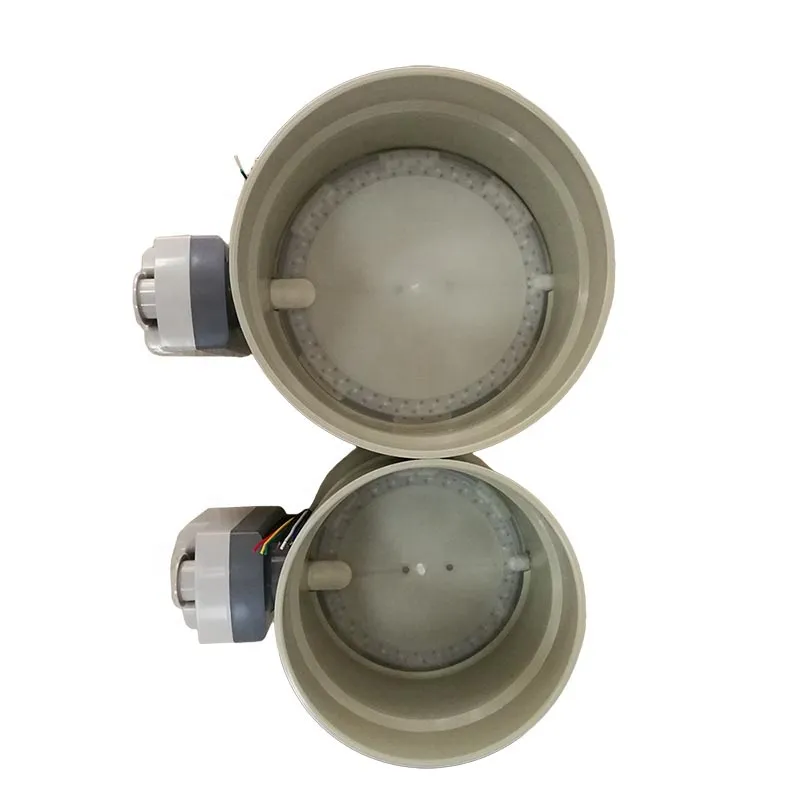
The motorized damper consists of the selected body, blade, shaft and electric actuator. The actuator package must be scheduled separately so a generic body family is not mistaken for a complete airflow-control system.
Power and Torque
XICHENG’s cataloged integrated actuator family uses AC/DC 24 V, but the exact actuator supplied with this air damper must be confirmed by tag. Select torque from blade area, maximum differential pressure, seals, shaft friction, deposits and an approved margin. Do not assign a voltage or torque only because it appears on another product page.
Command, Feedback and Failure Behavior
Define on/off or modulating command, signal range, direction, position feedback, end switches if required, travel time and behavior after power or signal loss. The wiring diagram and point list must describe the same sequence as the mechanical schedule.
Measured Airflow Requires Additional Scope
Actuator position does not prove airflow. If the project requires a VAV setpoint, airflow feedback, communication or a specified accuracy, identify the sensor, controller, calibration, straight-duct requirement and commissioning method as separate scope.
Laboratory and Corrosive Exhaust Applications
Laboratory General and Local Exhaust Branches
The PP/PVC motorized air volume control damper can be considered for a laboratory exhaust branch that must open, close or change blade position in response to an equipment or control command. PP or PVC construction is most relevant when the duct system is already plastic and the actual air stream has been reviewed for compatibility. The air damper can regulate branch resistance, but system airflow and room pressure still depend on the fan, duct network and control strategy.
For a fume hood or other safety-related local exhaust point, define the accepted minimum airflow and alarm sequence separately. A blade command without measured airflow does not prove containment. Where variable airflow is required, the project must identify the sensor, controller and commissioning method or select a purpose-designed laboratory airflow valve.
Etching and Electroplating Equipment Exhaust
XICHENG product information identifies etching and electroplating production-line ventilation as applications for plastic motorized air volume control dampers. These processes can produce humid, corrosive or deposit-forming exhaust, so the inquiry should include the chemical list, bath or process condition, mist and condensate behavior, cleaning method and upset temperature.
The air damper should be located where the body, actuator and wiring can be inspected without exposing personnel to an uncontrolled release. If deposits can harden around the blade or shaft, the design must provide cleaning access and the maintenance plan must include functional travel checks. Material compatibility alone does not prevent mechanical fouling.
Exhaust-Treatment and Industrial Ventilation Branches
A motorized duct damper may coordinate branches connected to a scrubber, adsorption unit or other exhaust-treatment system. It can isolate an inactive process branch or change resistance as part of a defined operating sequence. The fan and treatment unit still require their own capacity, pressure and control review; closing one branch can change pressure and airflow elsewhere in the network.
When the air damper is interlocked with a fan or VFD, document startup order, minimum open position, proof-of-position signal, fault response and shutdown sequence. The system should not rely on an assumed blade position if an incorrect position could reduce capture or overload another branch.
Where Project Review Is Mandatory
Engineering review is mandatory for high or low temperatures outside ordinary service, flammable or explosive atmospheres, high particulate loading, condensing exhaust, toxic service, high static pressure, critical containment, rapid cycling or a required leakage class. These conditions can change material selection, actuator torque, enclosure protection, sealing, documentation and maintenance requirements.
The product is not automatically suitable for outdoor exposure, washdown, hazardous locations, life-safety smoke control or emergency isolation. State those duties explicitly so the quotation can confirm a documented configuration or redirect the project before the air damper is specified.
Motorized air air-air damper selection Procedure
Select the electric duct damper in the order that the system makes decisions: define the duty, establish the airflow and pressure condition, coordinate the duct and material, then specify the actuator and controls. Starting with voltage or nominal diameter leaves the most important operating requirements unresolved.
Step 1: Define the Required Operating Duty
State whether the air damper provides equipment enable/disable, branch isolation, two-position diversion, proportional blade positioning or the final control element in a measured airflow loop. Define normal, startup, shutdown, emergency and power-loss positions. If tight shutoff or a certified leakage class is required, include the test standard and allowable leakage rather than using the general word “closed.”
Step 2: Confirm Flow, Pressure and Duct Geometry
Provide minimum, normal, maximum and emergency airflow where they apply, together with the static pressure available at the installed location. Add duct shape, nominal and actual dimensions, nearby fittings and installation orientation. These inputs allow the designer to check velocity, local resistance, blade clearance and the mechanical load that the actuator must overcome.
Step 3: Select Material and Connection
Compare the applicable PP, flame-retardant PP, PVC, acrylic or metal construction against the complete chemical and temperature schedule, then select a catalog or custom body. Coordinate the socket, flange, sealed or custom interface with the actual duct. Record body, blade, shaft, seal or bushing materials separately.
Step 4: Schedule Actuator and Controls
Confirm the selected actuator supply, then define command, feedback, fail state, travel requirement, enclosure condition and control-panel boundary. If a PLC, BMS, fume hood controller or airflow sensor is involved, provide the control narrative and point list. The air damper schedule and controls schedule must describe the same sequence.
Step 5: Confirm Submittal and Acceptance Requirements
List the drawing, wiring diagram, material statement, certificate, functional test and inspection records required before shipment. Define how the installed air damper will be accepted: visual inspection, end-position proof, command/feedback check, measured airflow, pressure test or another project method. Requirements added after fabrication may force changes to the actuator, body or documentation scope.
Fit, Not-Fit and Alternative Products
When Manual Balancing Is Sufficient
If the branch is balanced once during commissioning and does not need remote movement, an electric actuator adds wiring, controls and maintenance without changing the basic balancing task. Evaluate the PP/PVC round air volume control damper for a fixed manual setting. The selected position should still be established by field measurement.
When Pressure-Independent CAV or VAV Is Required
If the specification requires a fixed airflow despite changing duct pressure, use a documented CAV mechanism and operating range rather than an open-loop blade position. If the setpoint must change while pressure independence is maintained, use a documented VAV family. The CAV Venturi air valve and VAV Venturi air valve pages describe those separate selection paths.
When a Laboratory Closed-Loop Butterfly or Iris Product Fits Better
A laboratory VAV butterfly damper is a better comparison when the project starts with a defined variable-airflow measurement and control strategy. Where the mechanical concept calls for a concentric aperture and an associated pressure/flow relationship, compare the motorized iris damper. These products should not be chosen from shape alone; the control principle and evidence requirements differ.
Life-Safety, Isolation and Liquid Service
Do not specify the electric duct damper as a fire or smoke damper without the required life-safety listing, as a gas-tight isolation damper without a documented leakage test, or as a liquid-process butterfly valve. These duties involve different codes, seals, pressure ratings, actuators and acceptance tests. Use a product specifically designed and documented for the required service.
Installation and Commissioning
Mechanical Installation and Service Access
Install the air damper in the orientation shown on the approved drawing and support the adjoining duct so its weight does not distort the body. Keep the selected socket, flange, sealed or custom connection aligned. Before completing the joint, manually or electrically check that the blade clears the body and that the actuator can travel without contacting insulation, supports or nearby equipment.
Provide a service envelope around the actuator, shaft and removable covers. Do not bury the actuator above an inaccessible ceiling or place the blade shaft where condensate and deposits cannot be inspected. If the process can release hazardous gas, locate service access and isolation points so maintenance does not require opening an uncontrolled branch.
Electrical Wiring and Control Checkout
Verify the actuator nameplate against the scheduled voltage before energizing it. Follow the supplied wiring diagram, protect the circuit as required and separate wiring classes where the project standard requires it. Confirm command polarity or contact logic, end switches, feedback and power-loss behavior before connecting the air damper to the final BMS, PLC or equipment controller.
Stroke the actuator through every required position while observing the blade. A controller display or feedback value should not be accepted if the blade or coupling does not move accordingly. Record open and closed indications, intermediate-position response where used and any mechanical stop settings.
Airflow Measurement and Functional Testing
Test the air damper under the system conditions that matter to the sequence. For an on/off branch, verify the operating order with the fan and connected equipment. For modulating use, measure airflow at selected commands and confirm that the control loop remains stable over the required operating range. If the system pressure changes during different operating modes, repeat the check under those modes.
Acceptance should distinguish actuator position from measured airflow. Record both when airflow matters. If the branch cannot reach its design flow with the air damper fully open, investigate fan pressure, duct resistance, blockage and other branch settings before increasing actuator force or modifying the blade.
Maintenance and Recommissioning
Inspect the blade edge, shaft area, body, connection and actuator bracket for deposits, chemical attack, distortion or loose hardware. Exercise the air damper through its required travel and compare command with feedback where provided. Cleaning methods must be compatible with the plastic and seal materials and must not force the blade beyond its stops.
Recommission the branch after changes to fan speed, scrubber packing, filters, duct layout, connected equipment or control logic. These changes can alter the relationship between blade position and airflow even when the air damper itself has not moved.
Customization and Quotation Deliverables
Made-to-Order Construction
The PP/PVC motorized air volume control damper family can be configured around PP or PVC material, molded or fabricated body construction, round or rectangular duct geometry, project-specific connection and a selected electric actuator. Customization is useful only when each change is tied to a documented requirement. An unspecified “custom air damper” leaves the fabricator to guess the interface and controls.
For a nonstandard diameter or rectangular body, provide a dimensioned duct drawing and the airflow/pressure condition. For a nonstandard actuator package, provide the electrical schematic, point list and sequence of operation. Changes to size, blade, shaft or seals can alter actuator torque and body reinforcement, so mechanical and controls changes must be reviewed together.
Tag-by-Tag RFQ Checklist
- Air Damper tag, quantity, destination and requested document language
- Application and required operating duty
- Minimum, normal, maximum and emergency airflow where applicable
- Available static pressure and duct operating modes
- Round diameter or rectangular width/height and duct material
- Connection dimensions, wall thickness and field/factory joint scope
- Gas composition, concentration, humidity/condensate and temperature
- Installation orientation, actuator side and available service space
- Required actuator supply and applicable AC/DC/frequency details
- On/off or proportional command, feedback and fail position
- Controller, sensor, BMS/PLC, alarm and interlock requirements
- Leakage, pressure-drop, cycle-test or functional-acceptance requirements
- Required drawings, certificates, declarations and inspection records
What the XICHENG Quotation Should Return
The quotation should return a proposed model and size, body/blade/shaft material schedule, actual connection dimensions, actuator model and power, command and feedback interfaces, fail behavior, included controller or sensor scope, confirmed operating limits, document list, exclusions, price and delivery terms. Unresolved chemical, electrical or test requirements should remain visible instead of being hidden behind a generic product description.
Before fabrication, the approved technical schedule and drawing should use the same tag numbers as the project duct and controls schedules. This creates a traceable definition for manufacturing, installation, commissioning and future replacement.
Frequently Asked Questions
Is this automatically a VAV airflow-control valve?
No. A standard motorized damper moves a blade from an electrical command. Measured-airflow VAV control requires the corresponding sensor, controller, calibration and commissioning scope.
Which body materials are published?
The catalog lists PP, flame-retardant PP, PVC and acrylic round bodies plus custom flame-retardant PP, galvanized-steel and stainless-steel round or rectangular bodies.
Which diameters are available?
The answer depends on material and connection. Published groups include flame-retardant PP socket bodies at 50-90 and 110-315 mm, PP and PVC socket bodies at 63-315 mm, flame-retardant PP socket/flange bodies at 160-315 mm, sealed PP/PVC bodies at 110-315 mm, transparent PVC at 160-315 mm, and acrylic at 250 or 315 mm.
Which actuator voltage is supplied?
The cataloged integrated actuator family includes AC/DC 24 V, but this page describes a made-to-order air damper family. The selected voltage, torque, command, feedback, travel time and fail behavior must be returned for each tag.
Can it provide tight shutoff?
The PDF identifies sealed-body options but does not publish one universal leakage class. State the required leakage or isolation criterion before selection and obtain a documented configuration.
Can the air damper be used for corrosive exhaust?
It can be evaluated after reviewing the actual chemicals, concentrations, temperatures, condensate and every exposed component. No material name is a universal compatibility guarantee.
What information is needed for quotation?
Send airflow modes, available pressure, duct dimensions, selected material and connection, air-stream conditions, orientation, actuator supply, command, feedback, fail state, control schematic, quantity and destination.
Contact the Xicheng Engineering Team Today
Send the air damper schedule, duct drawing, airflow and pressure conditions, PP or PVC requirement, exhaust composition, actuator voltage and control sequence. We will review the body size, connection, material schedule, actuator and control scope, then return a project-specific technical proposal and pricing within 24 hours.
Shenzhen Office: No. 34 Zhenxing Road (Shengtaian Heavy Industrial Park B), Loucun, Guangming New Dist, Shenzhen, Guangdong, China
WhatsApp: +86 181 2647 8161
Engineering Mailbox: fanalax34@gmail.com