


Description
Round air volume control air-air damper selection Summary
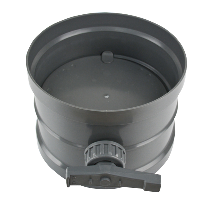
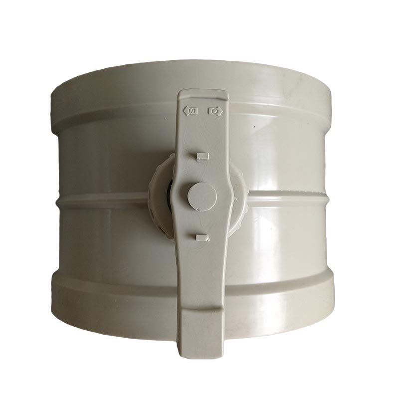
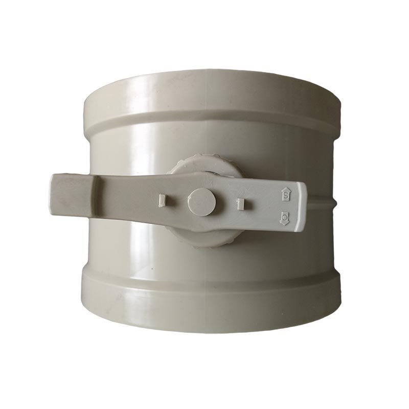
This product family uses a manually positioned rotating blade to add branch resistance during testing and balancing. It is suitable when the final blade position can remain fixed between service visits and the project does not require remote modulation, measured-airflow control or mechanical pressure compensation.
Choose This Product Family When
- The duct is round and requires a manual balancing or throttling point.
- The material and connection can be selected from a documented family that matches the actual duct system.
- A technician can reach, position and lock the operator during commissioning.
- The fan and duct design provide enough pressure for the required airflow after the air damper resistance is added.
Catalog Families to Compare
| Body Family | Connection | Published Diameter Range | Catalog Color |
|---|---|---|---|
| Flame-retardant PP | Socket | 50-600 mm | Beige or dark gray |
| PP | Socket | 50-500 mm | White |
| PVC | Socket | 63-315 mm | Dark gray |
| Flame-retardant PP sealed | Sealed-body connection | 110-315 mm | Beige or dark gray |
| Flame-retardant PP | Flange | 160-315 mm | Beige |
| Transparent PVC | Flange | 160-315 mm | Transparent |
These ranges belong to separate catalog families. They cannot be merged into one promise that every material, color and connection is available at every diameter. Custom round bodies in PP, flame-retardant PP, galvanized steel or stainless steel are reviewed from the project drawing.
Do Not Select It for Another Duty
This manual damper is not a VAV valve, constant-air-volume controller, passive backdraft damper, fire/smoke damper or certified isolation device. If the blade must move from a control signal, select a motorized family and define the actuator separately.
Information Required for Quotation
Provide the tag, design airflow, actual duct diameter and material, required connection, air-stream chemistry and temperature, available pressure, orientation, operator side, balancing objective, quantity and duct drawing. The returned schedule should identify one applicable family, actual mating dimensions, body length, blade and shaft construction, operator, service clearance and commercial scope.
Key Specifications
The catalog establishes the product mechanism and the available material/connection families. Project-specific operating limits and fabrication dimensions remain on the quotation and approved drawing.
| Specification | PDF-Confirmed Family Data | Project Confirmation |
|---|---|---|
| Product type | Manual round air volume control damper | Balancing or throttling duty |
| Mechanism | Rotating blade with manual operator | Operator and locking arrangement |
| Plastic body families | PP, flame-retardant PP and PVC | Complete exposed-component compatibility |
| Metal custom families | Galvanized steel and stainless steel | Grade, finish, dimensions and fabrication |
| Connections | Socket, sealed-body and flange families | Actual mating geometry and joint method |
| Published diameter coverage | 50-600 mm maximum catalog span; exact range depends on family | Select only from the applicable material/connection row |
| Airflow and pressure drop | Not published as one universal value | Calculate for selected diameter and blade setting |
| Temperature and chemical service | Not published as one universal value | Review actual stream and complete component schedule |
| Leakage or shutoff | No universal leakage class published | State requirement before selection |
| Final dimensions | Made to the selected family and project | Approved fabrication drawing governs |
Values That Must Stay Configuration-Specific
Do not transfer the 600 mm upper limit from flame-retardant PP socket construction to PVC, flange or sealed bodies. The same rule applies to color and connection. Each tag must resolve to one buildable combination.
Fields Added to the Approved Schedule
The project schedule should add actual inside/outside dimensions, body length, blade and shaft materials, operator, locking arrangement, service clearances, allowed orientation, design airflow, available pressure and any leakage requirement.
Manual Round Duct damper Overview
What Is a Round air volume control damper?
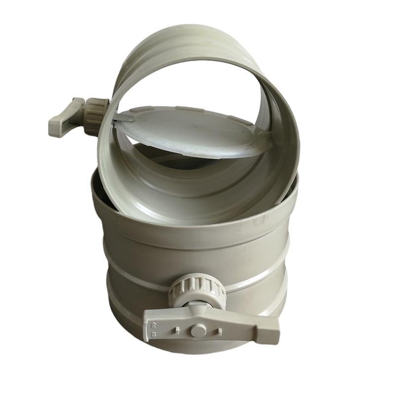
A round air volume control damper is an inline duct component that changes airflow resistance by rotating a blade inside a circular body. In the manual round air damper configuration, an operator sets the blade position mechanically. Opening the blade reduces the obstruction presented to the air stream; closing it increases resistance and normally reduces the branch airflow at the current system operating point.
This makes the air damper useful as a balancing point in a duct network. A commissioning technician can measure the branch flow, adjust the blade and repeat the measurement until the accepted airflow is reached. Once the position is secured, the air damper remains at that setting until someone changes it or until the system is rebalanced.
How the Manual Butterfly Blade Regulates Airflow
The product uses a butterfly-style motion: the blade rotates across the circular flow path rather than translating along the duct. Blade angle changes the effective open area and the local pressure loss. The resulting airflow is determined by the entire system, including fan performance, upstream and downstream duct resistance, filters, scrubbers, terminals and the positions of other air dampers.
For that reason, the air damper should be treated as an adjustable resistance element, not as an airflow source. It can redistribute or restrict available airflow, but it cannot make an undersized fan deliver the required volume or correct an exhaust system with excessive total resistance.
What Manual Blade Position Does Not Prove
A nominal handle position such as half open is not a calibrated percentage of design airflow. The relationship between blade angle and flow is nonlinear and changes with duct velocity, static pressure and the rest of the network. Two identical air dampers at the same angle can carry different airflows when installed in different branches.
The accepted setting therefore comes from field measurement. Record the measured airflow, system condition and final blade position together. If the fan speed, filter loading, scrubber resistance, duct layout or other branch settings change, the original position may no longer produce the same result and the system should be checked again.
Material and Connection Options
The PDF lists PP, flame-retardant PP, PVC, galvanized-steel and stainless-steel round air damper families. Material selection must follow the actual air stream and the complete exposed-component schedule, not the body label alone.
PP and Flame-Retardant PP
Standard PP socket bodies are published in white from 50 to 500 mm. Flame-retardant PP expands the catalog options: beige or dark-gray socket bodies from 50 to 600 mm, sealed bodies from 110 to 315 mm, and beige flange bodies from 160 to 315 mm. The quotation must identify which PP family applies rather than combining their ranges.
PVC and Transparent PVC
Dark-gray PVC socket bodies are published from 63 to 315 mm. Transparent PVC flange bodies are published from 160 to 315 mm. Confirm the formulation, air-stream compatibility, mating dimensions and joint method for the selected configuration.
Galvanized-Steel and Stainless-Steel Custom Bodies
The catalog also identifies custom round galvanized-steel and stainless-steel air dampers. Their diameter, sheet construction, grade or coating, blade/shaft materials, connection and operator are project-specific and must be returned on the approved drawing.
Diameter, Connection and Duct Integration
Select the Catalog Family Before the Diameter
Start with material and connection, then select a diameter within that row’s published range. A 500 mm PP socket air damper and a 500 mm flame-retardant PP socket air damper are catalog possibilities, while a 500 mm PVC socket or flange body is not established by this PDF.
Nominal diameter does not define outside diameter, wall thickness, insertion depth, flange geometry or body length. The approved drawing must match the actual duct schedule and show the operator side and blade travel.
Coordinate Airflow and Available Pressure
The design airflow and selected diameter establish duct velocity, while blade angle adds resistance. Check pressure loss and noise at the intended balancing point. A air damper should not be used to conceal an incorrectly sized branch or insufficient fan pressure.
Connection and Installation Drawing
Identify socket, sealed-body, flange or custom fabricated connection on every tag. Provide actual mating dimensions, support arrangement, nearby fittings and service access. The drawing should also state who supplies and completes adapters, gaskets, fasteners or field joints.
Laboratory and Corrosive Exhaust Applications
Laboratory General Exhaust Branches
A manual round air volume control damper can provide a fixed balancing point in a laboratory general-exhaust branch when the required airflow is established during commissioning and does not need continuous automatic reset. The air damper is most useful where technicians can access the operator, measure the branch flow and secure the final position.
It should not be used as the only control element for a fume hood or room whose airflow must respond automatically to sash position, occupancy, room pressure or a BMS command. Those applications require a defined sensor, controller and modulating device strategy in addition to system testing.
Corrosive Fume and Chemical-Process Exhaust
PP or PVC construction may be evaluated for localized chemical exhaust where the air stream and the surrounding duct system are compatible with the selected plastic. Examples can include extraction branches serving wet benches, chemical storage ventilation or process enclosures, provided that the actual chemicals, concentration, temperature and condensate conditions have been reviewed.
The air damper regulates available airflow; it does not capture contaminants at the source or treat the exhaust. Hood geometry, pickup velocity, duct transport velocity, fan selection and downstream treatment remain separate parts of the ventilation design. A wet scrubber, activated-carbon unit or other treatment device must be selected from the contaminant load and discharge requirements.
Compatible PP/PVC Duct Systems
The socket, sealed-body and flange families allow the air damper to be coordinated with compatible round-duct systems. It can be integrated with straight duct, elbows, tees, reducers and equipment connections as part of a fabricated exhaust network. Place the operator where it remains accessible and where nearby fittings do not obstruct blade movement or balancing work.
Material continuity is useful, but it is not the only design criterion. Supports, thermal movement, joint workmanship and cleaning access still need review. The air-air damper body should not carry loads from misaligned duct sections or unsupported equipment.
Applications Requiring Another Air Damper or Valve
Choose a motorized air volume control damper when the blade must respond to an electrical command. Choose a CAV or VAV air valve when the project requires defined airflow control as duct pressure changes. Choose a backdraft damper when the required function is passive one-way closure. Fire, smoke and certified isolation duties require products with the applicable construction and test documentation.
Do not use the manual round air volume control damper page as evidence for hazardous-area approval, a leakage class, a fire rating or a pressure-independent control function. These are separate performance claims that require separate product evidence.
How to Select the Air Damper
Start with Design Airflow and Duct Diameter
Begin with the minimum, normal and maximum design airflow for the branch, even though the air damper itself is manually set. Match those values to the proposed round-duct diameter and calculate the corresponding velocities. This establishes whether the duct size is reasonable before blade resistance is added.
If the project already has a duct schedule, provide both nominal and actual dimensions. For a new branch, coordinate the diameter with the fan, terminal device, transport-velocity requirement, noise target and available space. The air damper should not be used to conceal a fundamentally incorrect duct size.
Review Velocity, Available Pressure and Pressure Drop
The selected branch flow is only achievable when the fan can overcome the total system resistance. Identify the static pressure available at the proposed air damper location and the pressure losses from duct length, fittings, filters, treatment equipment and terminals. The air damper then uses part of the remaining pressure to balance the branch.
A project that needs a guaranteed pressure drop at a stated airflow should request the applicable product curve or engineering confirmation. Do not estimate the result from a generic round air damper because blade shape, body geometry and angle affect the relationship.
Define the Required Balancing and Shutoff Function
State whether the air damper is intended for initial balancing, occasional seasonal adjustment or routine operator control. Also state whether full closure is expected. A air volume control damper can restrict a branch, but that does not automatically make it a tight shutoff or isolation device.
If the branch must close automatically during an alarm, maintain a changing airflow setpoint or prevent reverse flow when the fan stops, the manual round duct damper is not the complete functional solution. Select the corresponding motorized, airflow-control or backdraft product instead.
Confirm Chemistry, Temperature and Material
Provide the normal and upset air-stream composition, concentrations, temperature, humidity and expected condensate or deposits. Use this information to compare PP and PVC and to confirm the exposed blade, shaft, bushing and seal materials. General laboratory use is not enough detail for a compatibility decision.
Check Access, Orientation and Connection Details
Confirm horizontal or vertical installation, airflow direction where relevant, operator side, nearby walls and fittings, and the space needed to rotate and secure the handle. Coordinate the selected socket, sealed, flange or custom connection with the duct fabricator. The approved drawing should remove ambiguity before the air damper reaches the site.
Installation and Commissioning
Install without Distorting the Round Body
Verify the air damper tag, material, actual diameter, blade movement and connection detail before installation. Align the adjacent duct so the body is not pulled into position by force. The selected joint and support work should preserve circular geometry and prevent duct loads from transferring into the air damper.
Before completing inaccessible joints, move the blade through its intended travel and check for contact or abnormal resistance. Protect the interior from fabrication debris, dust and loose hardware. Remove temporary transport restraints according to the supplied drawing.
Preserve Handle and Blade Service Clearance
Place the manual operator where it can be reached after duct supports, insulation, ceilings and nearby equipment are installed. Allow space to move the handle, read any position marking and secure the accepted setting. Do not bury the operator behind a permanent wall or place it where routine adjustment requires dismantling the duct.
Where the air damper is close to an elbow, tee, reducer, fan or treatment-device connection, coordinate both access and the airflow measurement location. The balancing team needs a usable traverse or measurement point; a handle that is accessible but cannot be associated with a reliable airflow reading does not complete commissioning.
Measure Branch Airflow and Record Final Position
Commission the air damper with the system in its defined operating condition. Confirm fan operation and the intended positions of other air dampers, then measure the branch airflow using the project-approved method. Adjust the blade in controlled increments, allow the reading to stabilize and repeat until the accepted value is reached.
Record the final airflow, system condition, instrument or method, air damper tag and secured blade position. This record provides a baseline for future troubleshooting. Do not report the handle angle alone as the commissioned airflow.
Rebalance after Fan, Filter or Duct Changes
Manual balancing is tied to the system resistance present at the time of commissioning. Fan-speed changes, filter loading, scrubber modifications, duct extensions or adjustments in neighboring branches can shift the airflow. Recheck affected branches after these changes rather than assuming the original setting remains valid.
Inspection and Maintenance
Inspect the Blade, Shaft, Handle and Duct Joint
Inspection frequency should reflect the air stream and operating history. Check that the handle remains secured, the shaft moves without abnormal resistance and the blade is not obstructed by deposits. Examine the selected duct connection and supports for distortion, cracking or movement that could affect blade clearance.
If the air-air damper position has changed unexpectedly, investigate the cause before restoring the previous mark. A loose operator, maintenance activity or a system change may have altered the setting, and the branch airflow should be measured again.
Clean Deposits without Damaging Plastic Components
Use a cleaning method compatible with the confirmed body, blade, shaft, bushing and seal materials. Remove deposits that interfere with blade travel, but do not use an unapproved solvent, excessive heat or abrasive tool simply because the main body is plastic. Isolate the ventilation system according to the site’s maintenance procedure before opening or working on the duct.
When to Reconfirm Airflow
Reconfirm the branch airflow after the air damper is moved, cleaned or repaired, and after changes to the fan, filter, treatment device or duct network. A measured check is also appropriate when laboratory use changes or when users report altered capture or room-pressure behavior.
Product and System Boundary
Manual damper vs Motorized air volume control damper
The manual round air volume control damper holds a field-set position and requires direct adjustment. A motorized air volume control damper adds an actuator and electrical command interface so the blade can be repositioned remotely. Motorization alone does not create measured CAV or VAV control; the complete control loop must define sensing, logic, feedback and commissioning.
Manual damper vs CAV or VAV Air Valve
A CAV or VAV air valve is selected around a defined airflow-control task. Depending on the product, it may include pressure compensation, sensing, an actuator and a controller. The manual round duct damper provides adjustable resistance only. It does not maintain a set airflow as static pressure changes.
Manual damper vs Backdraft, Fire and Smoke Damper
A backdraft damper uses airflow direction or pressure difference to permit forward flow and resist reverse flow. Fire and smoke dampers are life-safety products governed by specific construction, actuation, installation and test requirements. The manual round air volume control damper should not be scheduled for those functions.
Customization and RFQ Checklist
Tag-by-Tag Buyer Inputs
Prepare one line for each air damper tag. Include the service description, design airflow, nominal and actual duct dimensions, PP or PVC duct material, normal and upset gas composition, concentration, temperature and moisture, available static pressure, installation orientation, operator side, balancing or shutoff objective, quantity and destination.
Attach the duct layout or fabrication drawing when possible. Mark nearby elbows, tees, reducers, supports, walls and equipment connections so the operator and selected joints can be coordinated. State any required documentation, inspection, packaging or identification tags at the quotation stage.
What the XICHENG Quotation Should Return
The technical response should identify the proposed material configuration, model, diameter, actual connection dimensions, body length, blade and shaft arrangement, manual operator, supplied connection scope and applicable operating limits. It should also list assumptions, unresolved chemical-compatibility items, drawing requirements, commercial price and delivery terms.
For any custom construction outside a published material/connection range, the response should confirm the body, blade, shaft, supports and dimensions. Do not release fabrication from a generic family description when the installation depends on project-specific geometry.
Frequently Asked Questions
Is this a manual or motorized damper?
This page describes manually positioned round air dampers. Projects requiring remote blade movement should select a motorized family and define power, command, feedback and failure behavior.
Which diameter range is available?
It depends on material and connection. The PDF publishes 50-600 mm for flame-retardant PP socket bodies, 50-500 mm for PP socket bodies, 63-315 mm for PVC socket bodies, 110-315 mm for flame-retardant PP sealed bodies, and 160-315 mm for flame-retardant PP or transparent PVC flange bodies.
Are galvanized-steel and stainless-steel bodies available?
Yes. The catalog identifies custom round galvanized-steel and stainless-steel air dampers, but it does not print one universal diameter table for them. The quotation and drawing must establish the actual construction.
How do I choose the material?
Compare the actual gas composition, concentration, temperature, moisture, deposits, duct material and cleaning method against every exposed component. Do not select only from the body name or color.
Does the air damper measure or control airflow automatically?
No. It provides an adjustable mechanical restriction. Airflow must be measured during balancing, and the operator is then locked at the accepted setting.
Is this a backdraft or shutoff air damper?
No. Reverse-flow closure, certified isolation and fire/smoke protection are separate duties that require specifically documented products.
What must be confirmed before ordering?
Provide the tag, airflow, actual duct dimensions, selected material and connection, air-stream conditions, available pressure, orientation, operator side, balancing objective and duct drawing. XICHENG will return the applicable family and approved fabrication details.
Contact the Xicheng Engineering Team Today
Send the round-duct schedule, design airflow, PP or PVC material requirement, exhaust composition, installation drawing and required manual balancing function. We will review the air damper diameter, connection dimensions, material configuration, operator access and quotation scope, then return a project-specific proposal and pricing within 24 hours.
Shenzhen Office: No. 34 Zhenxing Road (Shengtaian Heavy Industrial Park B), Loucun, Guangming New Dist, Shenzhen, Guangdong, China
WhatsApp: +86 181 2647 8161
Engineering Mailbox: fanalax34@gmail.com