


Description
PP/PVC Ventilation Duct Selection Summary
Choose This Product Family When
Use this family when a laboratory or process exhaust route requires rigid PP or PVC duct sections with project-defined geometry. It can cover round branches, round headers, fabricated rectangular mains and transitions coordinated with source-capture and treatment equipment.
The project should already distinguish duct conveyance from airflow generation and control. Straight duct sections connect the system; they do not replace the fan, balancing devices, room controls or treatment equipment. A coordinated inquiry therefore includes the entire flow schematic even when only duct is being purchased.
Key Product-Family Data
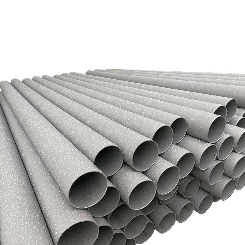
XICHENG sources confirm round PP/PVC ventilation duct, custom PP rectangular duct, gas service, welded construction and sleeve or flange connection options. Round and rectangular products use different manufacturing methods and model references, so this combined family page does not assign one artificial SKU.
Round and rectangular PP/PVC ventilation duct evidence is retained in the project research without repeating internal product codes on the buyer-facing page. The final schedule should identify shape, material, dimensions and construction for every tagged section so a buyer can compare scope without relying on the model alone.
Do Not Select from Material and Diameter Alone
A usable duct schedule also needs airflow, section length, wall or reinforcement basis, joint type, support conditions, temperature, chemistry and available pressure. Do not treat marketplace liquid-pipe pressure fields as ventilation-duct ratings or assume that a resin name guarantees suitability for every mixture.
For rectangular sections, width and height also determine aspect ratio and panel behavior. For round sections, the mating outside dimension and end preparation determine whether a sleeve, fitting or damper will connect. These details belong above the commercial price comparison.
Information Required for a Project-Ready Quotation
Send the route drawing, airflow at each section, diameter or W x H, section lengths, elevations, fittings, joints, supports, indoor/outdoor exposure, gas conditions and quantities. The return should identify material, construction, connections, fabrication drawings, unresolved fields, documentation and commercial scope.
Mark site dimensions that cannot yet be verified as hold points. XICHENG can then price the defined package while reserving final adapters or closing pieces for approved measurements instead of embedding assumptions in fabricated duct.
Key Specifications and Order-Defining Data
Available Family Configuration
The family includes round and rectangular rigid plastic ventilation ducts for conveying laboratory and process exhaust gas. A project may use repeatable round branch sections, fabricated rectangular headers, or both shapes connected through controlled transitions. Final sections are made against approved dimensions rather than one universal stock table because route geometry, equipment interfaces and transport constraints differ from project to project.
The quotation should distinguish a straight production section from a fabricated spool that includes a branch, offset, flange or equipment transition. That distinction affects drawing detail, handling, joint count and field measurement responsibility even when both items use the same base material.
| Specification Field | Available Family Basis | Project Confirmation |
|---|---|---|
| Product configurations | Round and rectangular PP/PVC ventilation ducts | Use a section tag and drawing revision for each fabricated item |
| Material | PP or selected PVC configuration | Resin specification and exposure review |
| Cross-section | Round or square/rectangular | Diameter or W x H and orientation |
| Construction | Formed/extruded or fabricated welded duct | Method, wall and reinforcement by size |
| Connection | Welded, sleeve/socket or flange | Mating dimensions and supplied joint scope |
| Length | Standardized production or custom sections | Shipping, access and site-joint constraints |
Round and Rectangular Product Boundary
XICHENG product records separately document round PP ventilation duct and rectangular PP duct configurations. These references identify the underlying product families; they do not define every diameter, wall, connection or pressure condition. The WooCommerce page therefore represents both shapes without assigning one artificial SKU. Each quotation line should instead use a project section tag tied to the current drawing revision.
Performance Fields Require Conditions
Pressure loss depends on airflow, hydraulic geometry, section length and connected fittings. Leakage and deflection depend on wall construction, joints, reinforcement, supports and the positive or negative pressure acting on the section. Temperature capability also depends on the selected material and mechanical loading. These values belong in the quotation or engineering submittal with their applicable condition; an isolated number without shape, size and operating case is not enough to approve fabrication.
Where the designer has not finalized a field, the quotation should label the assumption and state whether it affects price, geometry or delivery. This makes later revision visible instead of allowing a provisional airflow or pressure value to become an undocumented production requirement.
Acceptance Documentation
Define whether the project needs a tagged fabrication drawing, section schedule, material identification, dimensional inspection, visual weld inspection, packing list or a specified leak test. The required document set should follow the risk and contract scope rather than being copied from an unrelated duct specification.
A test requirement must identify the tested section boundaries, positive or negative test condition, sealing of temporary openings, instrumentation, duration and acceptance criteria. It should also state whether testing occurs at the factory, after field assembly or at both stages, because a factory section test does not verify field-made joints.
Round Versus Rectangular Ventilation Duct
Round Duct for Branches and Efficient Routing
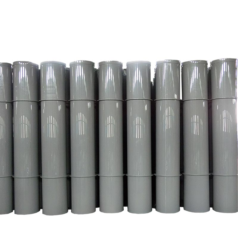
Round duct is confirmed across XICHENG’s round PP/PVC ventilation duct family and is commonly used for laboratory branches and mains. It provides a simple continuous perimeter and coordinates directly with round fittings, dampers, fans and equipment collars.
Round sections also simplify rotation during field coordination because the connection has no horizontal and vertical side designation. Installation still needs marked airflow direction, joint access and support locations.
Rectangular Duct for Space-Constrained Mains
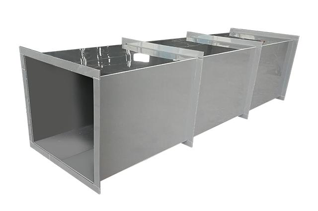
Rectangular PP duct is fabricated from sheet and welded, with reinforcement considered according to dimensions. It can use available ceiling width or height more effectively where a round diameter will not fit.
The tradeoff is a larger flat-panel area, more fabrication and orientation-dependent interfaces. Width, height, reinforcement and flange direction must remain visible on the drawing and packing label.
Compare Equivalent Airflow, Not Equal Width
Round diameter and rectangular width are not directly interchangeable. Compare cross-sectional area, velocity, pressure loss, aspect ratio, support and available installation envelope before choosing the shape.
A shallow rectangular duct may clear structure but require a wider route and more reinforcement. The system designer should check the full pressure budget and accessible ceiling zone rather than optimizing one dimension in isolation.
Mixed-Shape Systems Need Controlled Transitions
A project may use round branches and a rectangular header. Mark every round-to-rectangular transition with both end dimensions, alignment datum and available length, then include it in the pressure-loss model.
Identify whether top, bottom or centerline stays constant. This prevents a technically correct transition from arriving with the wrong offset for the installed elevation.
PP and PVC Material Options
PP Duct Construction
PP is the most consistently documented XICHENG laboratory-duct material. It can be formed or fabricated and hot-air welded into round or rectangular sections, allowing the duct route, branches and equipment transitions to be coordinated as one plastic system. That construction fact does not create universal chemical or temperature limits. Suitability still depends on the exact compounds, concentration, normal and upset temperature, condensate and cleaning method.
For an exhaust network, review not only the straight wall but also welding rod, flanges, gaskets, access closures, drain details and any exposed fasteners or supports. A compatible duct wall does not correct an incompatible seal or metallic component placed in the same air stream.
PVC Project Option
PVC appears in XICHENG PP/PVC duct listings and may be selected where the project specification and exposure permit it. The inquiry should identify the required grade and whether the surrounding system is already standardized on PVC. Do not join unlike plastics as though they were the same weld system, and do not carry PP assumptions for welding, movement or service limits into a PVC schedule without confirmation.
Material comparison should be made against the actual operating envelope and local project requirements, not color or initial price alone. If both PP and PVC are commercially acceptable, request that the quotation state the proposed material for every section and the reason any transition between materials is required.
Review the Complete Exposure
Include normal exhaust, startup and shutdown conditions, cleaning chemicals, upset temperature, humidity, droplets, solids and outdoor exposure. A branch from one fume hood may see a relatively defined stream, while a header downstream of several branches receives a combined mixture and may require a different compatibility decision.
Also identify whether vapors can condense after cooling, whether a scrubber can return moisture toward the duct, and whether deposits could accumulate at low points. These conditions influence slope, drainage, access and maintenance even when they do not change the selected base resin.
| Exposure Field | Buyer Input | Recorded Decision |
|---|---|---|
| Chemistry | Compounds, concentration and mixtures | Body and joint materials |
| Temperature | Normal and upset values | Applicable construction and stated limit |
| Moisture | Humidity, droplets and condensate | Drainage, slope and joint details |
| Deposits | Dust, crystals or sticky carryover | Access and cleaning provisions |
| Environment | Indoor/outdoor, UV and ambient corrosion | External protection and support materials |
Color Is Not a Resin Specification
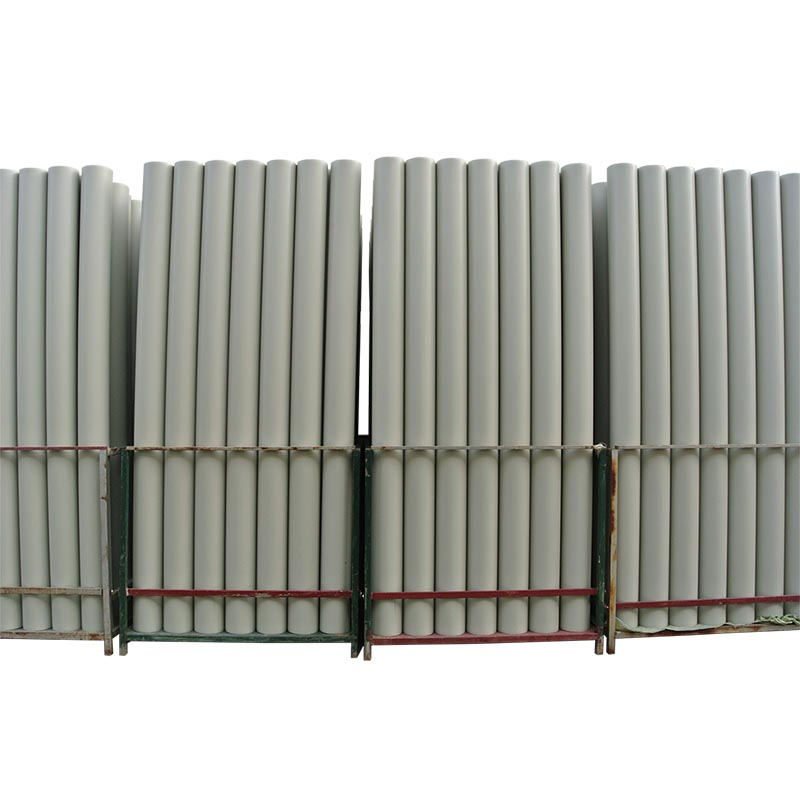
Gray and beige or cream products appear in XICHENG images. Color can help identify a supplied batch or match an existing installation, but it does not establish resin grade, flame performance, chemical compatibility, UV resistance or temperature capability. Those fields must be stated separately in the approved material and fabrication schedule.
Custom Sizes, Wall Construction and Reinforcement
Size from Airflow and Velocity
Determine diameter or W x H from design airflow, target velocity, allowable pressure loss, noise and available space. The selected area should work across the expected operating range, not only at one nominal point. Avoid selecting a duct solely because it matches an equipment collar: a transition may be preferable when the equipment outlet is not the correct size for the downstream route.
Record minimum, normal and maximum operating airflow where the system varies, together with simultaneous-use assumptions for branches. A duct sized only for one point may create excessive velocity and pressure loss at peak flow or poor transport behavior at low flow. The accepted section size should remain consistent in the fan calculation, equipment schedule and fabrication drawing.
Coordinate Section Length with Logistics
Long sections reduce field joints and can simplify the installed route, but they may not fit containers, elevators, doors, lifting paths or ceiling openings. Section length should balance factory fabrication, protective packing, shipping, site handling and access for the final joint. Large rectangular spools also need enough rigidity for transport without treating temporary packing braces as permanent supports.
Show field-joint locations on the installation drawing. A technically convenient factory length can become impractical if its joint lands above a wall, beam or inaccessible ceiling bay.
Wall Construction Is Configuration-Specific
Wall thickness and fabrication method depend on dimensions, shape, temperature, pressure condition, support spacing and reinforcement. Round manufactured duct and a large fabricated rectangular section do not necessarily use the same structural basis. Marketplace values from mixed liquid-pipe listings are therefore not used as universal ventilation-duct data.
The quotation should state the proposed wall or construction basis, reinforcement arrangement and any assumptions that remain open. Buyers can then verify that the offered configuration matches the negative or positive pressure condition rather than comparing thickness without context. A thicker wall is not a substitute for correct supports, panel reinforcement or connection design.
Rectangular Reinforcement
Large flat panels can require external reinforcement to control movement under operating pressure and handling loads. The drawing should show reinforcement location, spacing and external profile while preserving access to joints and preventing conflict with hangers, wall penetrations or adjacent services.
Reinforcement is part of the manufactured geometry and shipping envelope. Coordinate it with wall penetrations, access doors and nearby services before approval.
Allow for Thermal Movement and Loads
Supports, anchors and equipment interfaces must address thermal expansion, duct self-weight, fittings, condensate and external loads. Fixed points and guided movement should be coordinated with the route instead of allowing every flange to restrain expansion. Plastic flanges should not be used to pull misaligned sections into position or carry the weight of a fan, scrubber nozzle or unsupported vertical riser.
Outdoor runs also require review of wind, solar exposure, temperature variation, roof penetrations and weather protection. Vertical stacks need separate consideration of base support, guides and discharge components. The support designer should use project conditions and approved material properties rather than a generic spacing copied from another duct size.
Airflow, Pressure Loss and System Boundaries
Straight Duct Friction
Straight duct contributes friction according to airflow, hydraulic geometry, length and internal condition. The calculation should use each approved diameter or rectangular width and height, not a preliminary route size after fabrication has changed. Where several operating modes exist, evaluate the relevant airflow cases rather than assuming the maximum-flow path represents every control condition.
Maintain a consistent section schedule between the calculation and fabrication drawing. A late size change affects velocity, friction and every connected fitting or damper.
Fittings Add Local Loss
Elbows, tees, wyes, reducers, entries, exits and equipment transitions add local resistance. Their geometry and proximity to one another affect the route calculation, so the straight-duct page does not replace a fitting schedule or permit one pressure value to be applied to the entire network. Branch takeoffs should be checked against the required flow distribution, not selected only for fabrication convenience.
Changes close to fan inlets, control valves or sensors can also disturb the velocity profile. Locate components using their required installation conditions, not only the shortest physical route.
Negative and Positive Pressure Require Engineering
Laboratory exhaust commonly operates under negative pressure upstream of the fan, while fan-discharge or supply sections may be positive. Negative pressure can pull large panels inward; positive pressure changes joint loading and the direction of leakage. Construction, deflection, supports and leakage acceptance must therefore be reviewed for the actual location and operating condition.
State normal and upset pressure conditions when available. A negative-pressure branch upstream of a fan and a positive-pressure discharge section may need different construction or test boundaries within one project.
Duct Does Not Create or Control Airflow
The duct provides a conveyance path. Fans create the pressure difference, manual or motorized dampers change resistance, and CAV/VAV systems measure or regulate airflow according to their control package. A duct quotation therefore cannot confirm hood face velocity, room pressure or branch airflow unless the fan, controls, balancing procedure and operating cases are also defined. Coordinate these components through Laboratory Ventilation Components.
Commissioning should verify system airflow at defined points. A smooth, correctly installed duct is necessary, but its appearance alone does not demonstrate that each hood or room receives the required airflow.
Fittings, Dampers and Equipment Connections
Duct Fittings Complete the Route
Use PP/PVC Ventilation Duct Fittings for elbows, tees, wyes, reducers, transitions, flanges and couplings. Match every fitting to the duct dimensions, centerline or edge alignment and joining method. The fitting schedule should also identify orientation and rotation; a branch can have the correct diameter yet still be unusable when its takeoff points toward the wrong ceiling bay.
Keep fitting geometry synchronized with the pressure-loss calculation. Substituting a short elbow, abrupt reducer or different branch angle during fabrication can change both installation clearance and system resistance.
Manual and Motorized dampers
The round manual damper supports fixed balancing, while the motorized damper supports commanded blade positioning. Their schedule should state size, connection, access side and required straight-run or service clearance before the adjacent duct spools are released.
Do not use the duct to force a damper into alignment or support the actuator. Where a damper must be removed for service, provide a detachable joint arrangement and enough clearance to withdraw the body without cutting the main duct.
Backdraft and Airflow-Control Products
The backdraft damper responds passively to reverse flow. CAV and VAV valves address different control objectives and may require defined inlet conditions, sensing connections and commissioning access. Coordinate these needs before placing elbows, branches or transitions immediately beside the control component.
A straight duct section can be part of the required installation envelope, but it does not create the valve’s airflow accuracy. The approved component drawing and control sequence remain the governing documents.
Fans, Scrubbers and Hoods
Equipment flanges, flexible connections, maintenance clearances and loads must be coordinated from current vendor drawings. Fan inlet and discharge connections may need transitions and flexible elements, while scrubber nozzles may require drainage or removable spools. The plastic duct must not carry equipment weight or correct nozzle misalignment.
At the source end, record each hood collar and design airflow rather than assuming all laboratory outlets are identical. Browse Laboratory Fume Hoods when source capture is also in scope, and include the hood schedule in the duct RFQ.
Laboratory and Corrosive Exhaust Applications
Laboratory Branch and Header Networks
Round branches can collect fume hood, canopy and room exhaust into round or rectangular headers. This application is a good fit when the chemical inventory is known, each branch has a defined airflow and the route can provide access for balancing and maintenance. Tag every section with its source, airflow and service so a branch carrying a specific corrosive stream is not confused with general exhaust during fabrication or installation.
Where hoods operate in different combinations, include the diversity or simultaneous-use logic used to size the header. That operating basis belongs in the fan and controls design, but the resulting section airflow must be visible on the duct schedule.
Chemical Process Exhaust
PP/PVC duct may connect process pickups, enclosed tanks or local capture points to fans and treatment equipment when the selected material and joints are compatible with the actual stream. Provide compounds, concentrations, droplets, solids and temperature rather than using the general label “chemical exhaust.” The route should also identify where separate streams combine because compatibility and condensation conditions can change downstream of that point.
Processes that can create sticky deposits, crystals or liquid carryover need accessible low points, cleanouts or removable sections. The cleaning method must be compatible with the duct and should not push contamination into a fan or control device.
Scrubber and Fan Connections
Provide current nozzle drawings, flange dimensions, flexible-connection requirements, support loads and maintenance removal paths. At a fan, review inlet flow conditions and make sure the connected transition does not create an avoidable disturbance. At a scrubber, coordinate inlet elevation, drainage direction and any moisture that could return toward the duct during shutdown.
Duct must not carry unsupported equipment weight. Fans, scrubbers, stacks and vertical risers require their own structural support and movement strategy, with the plastic connection protected from imposed loads.
Not-Fit Applications
Do not use this page as a specification for liquid pressure pipe, fire-rated or smoke-control duct, a flexible vibration connector, structural support or certified airtight isolation. Those duties have different performance, approval and testing requirements. Exhaust containing combustible dust, explosive mixtures, unusually high temperature or regulated radioactive/biological material also requires a specialist design and documented compliance review before this family can be considered.
Ventilation Duct Selection Procedure
Map Airflow and Service
Start with sources, branch quantities, headers, fan and treatment equipment. Mark flow direction, normal and emergency operating modes, chemistry changes and every location where streams combine. The map should allow the designer and fabricator to trace one tagged section back to its source and design airflow without interpreting several disconnected schedules.
Add operating modes and emergency conditions so the schedule reflects the maximum route demand and any branch that is normally closed.
Select Cross-Section and Route
Compare round and rectangular options against airflow, pressure loss, ceiling space, reinforcement and fabrication requirements. Check the entire installation envelope, including external stiffeners, flanges, supports and working clearance, rather than comparing only the internal duct dimensions.
Coordinate the route with structure, cable trays, piping, lighting and access panels before fixing section dimensions.
Define Material and Construction
Review chemistry, temperature, moisture, deposits and external exposure, then specify PP or PVC, wall construction and reinforcement basis. Record unresolved compatibility questions before price comparison so alternative materials or operating limits remain visible in the quotation.
Apply the review by location because mixed streams and outdoor sections can create different exposures within the same system.
Coordinate Joints and Supports
Choose welded, sleeve/socket or flange interfaces according to installation sequence, leakage requirements and maintenance. Add supports without blocking joints, access covers or equipment removal. Mark which joints are completed in the factory and which require field labor, tools and consumables.
Use removable interfaces at equipment and planned service spools. Confirm who supplies gaskets, fasteners, flexible connectors and field weld materials.
Approve the Tagged Drawing
Check every diameter or W x H, section length, elevation, transition, branch rotation, flange and supplied item against the latest revision before manufacture. A drawing approval should also confirm material, connection type and section tag; approving geometry alone can leave a technically important scope conflict unresolved.
Keep comments in the controlled drawing rather than separate messages. Release only dimensions that have been verified or explicitly marked as pending.
Installation, Inspection and Maintenance
Inspect before Installation
Verify tags, dimensions, branch orientation, end preparation, visible weld condition, transport damage and cleanliness before lifting sections into the route. Compare critical equipment interfaces with the approved drawing while the section is still accessible. Quarantine any damaged or uncertain item instead of trimming a fabricated end before the disposition is agreed.
Keep labels attached until final placement and protect prepared ends from impact or site contamination.
Support without Distortion
Use project-engineered supports with adequate bearing area and avoid point loads on plastic walls, branches and flanges. Install the permanent support before releasing lifting equipment where practical. Hangers should restrain the route as designed while allowing the approved thermal movement and should not crush or ovalize round duct.
Place supports so section weight is not transferred through equipment nozzles or detachable joints.
Join with Adequate Access
Provide working clearance, lighting and a clean area for welding, sleeve insertion or flange tightening. Confirm that welding tools and compatible consumables are available for the selected material. Do not heat, jack or bolt flanges into alignment as a substitute for correcting the support or section geometry.
Dry-fit critical routes and verify eccentric transitions and branch rotations before completing permanent joints.
Inspect and Test to a Defined Method
Record dimensional, support and visual joint checks by tag. If leak testing is required, define boundaries, method, positive or negative pressure condition, temporary closure arrangement, instrumentation, duration and acceptance result. Coordinate the test with dampers and equipment so unapproved components are not exposed to the test condition.
Complete agreed tests before closing inaccessible ceilings or covering joints. Record actual results, not only a pass statement.
Maintain Access and As-Built Records
Keep cleanouts, removable spools, dampers and equipment interfaces accessible after ceilings and other services are complete. Update the duct schedule and controlled drawing after field changes, including replacement closing pieces or altered branch orientations, so later maintenance does not rely on the original fabrication layout.
Inspect low points, elbows and branch junctions where condensate or deposits may collect, using cleaning methods compatible with the selected plastic.
Custom Manufacturing and Quotation Deliverables
Minimum RFQ Dataset
Submit the current duct layout, section tags, operating airflow, dimensions, lengths, material preference, gas data, pressure condition, joints, supports, quantities and destination. Include equipment drawings, route elevations and site-access limits when available. If the complete fabrication schedule is not ready, identify which dimensions are fixed and which remain budget assumptions.
| RFQ Section | Buyer Input | XICHENG Return |
|---|---|---|
| Route | Tags, dimensions, lengths and elevations | Coordinated section schedule |
| Service | Airflow, chemistry, temperature and moisture | Proposed material and stated limits |
| Construction | Shape, pressure condition and support basis | Wall/reinforcement configuration |
| Interfaces | Joint and equipment drawings | Connection and supplied-scope notes |
| Project | Quantity, destination and documents | Lead time, packing, pricing and deliverables |
Drawing Approval
Controlled fabrication drawings should absorb all technical comments and identify unresolved site dimensions as hold points. Each released section should show the tag, material, shape, dimensions, orientation, connection and relevant reinforcement. Revision status must remain visible on the drawing and packing list so an obsolete spool is not installed merely because its dimensions appear similar.
Transparent Scope
The quotation should state whether the supply includes straight sections, fittings, dampers, equipment transitions, flexible connectors, supports, gaskets, fasteners, field welding consumables, testing, installation and as-built documentation. It should also state exclusions and any buyer-supplied measurements. This scope matrix prevents a complete duct route from being priced as disconnected material lengths.
Non-Standard Custom Product
The accepted schedule, quotation and drawing revision define the delivered duct, not generic marketplace dimensions. A project-ready return should make the proposed construction and unresolved fields auditable before production. Changes after approval should be processed by tag and drawing revision because even a small size or elevation change can affect several connected sections.
Frequently Asked Questions
Are round and rectangular ducts available?
Yes. XICHENG sources confirm both, with round and fabricated rectangular construction.
Are PP and PVC both available?
PP is directly documented and PVC appears in the PP/PVC family. Final selection depends on service and configuration.
What sizes are offered?
Dimensions are customizable. Submit each diameter or W x H; do not rely on inconsistent marketplace spans.
How are sections connected?
Available arrangements include welding, sleeve/socket and flanges according to the approved configuration.
Is rectangular duct always better in tight spaces?
No. It may fit a shallow ceiling, but aspect ratio, reinforcement, pressure loss and cost also matter.
What wall thickness should be selected?
It depends on size, shape, pressure, temperature, supports and reinforcement. It must be confirmed per project.
Can one material handle every laboratory gas?
No. Provide chemicals, concentrations, temperature, moisture and cleaning conditions for review.
Is this liquid pressure pipe?
No. This page specifies ventilation and exhaust gas ductwork, not a liquid piping pressure class.
Does the duct control airflow?
No. Fans and control devices establish and regulate airflow; the duct provides the conveyance path.
What speeds up quotation?
A tagged layout, airflow schedule, gas data, dimensions, interfaces, quantities and destination.
Contact the Xicheng Engineering Team Today
Send your duct layout, airflow schedule, round and rectangular dimensions, exhaust-gas conditions, joint preferences and equipment drawings. XICHENG will return a coordinated duct configuration, required approval information and quotation within 24 hours.
Shenzhen Office: No. 34 Zhenxing Road (Shengtaian Heavy Industrial Park B), Loucun, Guangming New Dist, Shenzhen, Guangdong, China
WhatsApp: +86 181 2647 8161
Engineering Mailbox: fanalax34@gmail.com