


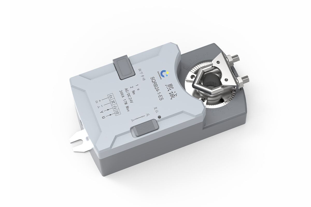
Description
A 1-second fast-acting damper actuator is used when a laboratory airflow sequence requires much faster blade positioning than a conventional 30-, 60-, or 120-second HVAC actuator can provide. This 2 Nm configuration accepts an analog command and returns position feedback for supervision by a compatible controller. It is the fastest rotary option in XICHENG’s laboratory airflow controls and actuators range, but total system response still depends on the sensor, controller, damper, duct, and commissioning settings.
The actuator is intended for project-configured ventilation dampers in laboratory supply, exhaust, fume hood and pressure-control applications. Its speed is one component of the control loop: the selected damper, airflow or pressure sensor, controller tuning, duct volume and fan response still determine how quickly the complete ventilation system reaches its target.
Product Selection Summary
Shortlist this 1-second damper actuator only after the mechanical load and control architecture have been defined. It is a fast, analog-positioning actuator for a compatible air damper; it is not a complete airflow controller, a mechanical spring-return device or a certified fire/smoke actuator.
Choose This Fast-Acting Damper actuator When
- The sequence requires rapid proportional movement rather than simple open/close operation.
- The damper requires no more than the published 2 Nm rated torque under the worst expected operating condition.
- A 24 V AC/DC supply and a 0(2)–10 V DC or 0(4)–20 mA control signal are available.
- The controller can receive the actuator’s 2–10 V DC position-feedback signal.
- The shaft and available mounting space match the published clamp and enclosure dimensions.
- The complete control loop will be commissioned for the required airflow, pressure or face-velocity response.
Evaluate Another Actuator Type When
- Only two-position open/close movement is required. Use an on/off or two-position damper actuator.
- The damper must move mechanically to a defined position after power loss. Use a spring-return product with documented return behavior.
- The design requires RS-485 or Modbus communication at the actuator. Evaluate a communicating modulating damper actuator.
- The required damper torque exceeds 2 Nm. Select a higher-torque actuator and verify its runtime, shaft and signal interface.
- The application is a fire or smoke control assembly. Use an actuator and damper combination carrying the required project listing and certification.
Information Required for a Project-Ready Quotation
Provide the damper type and size, required torque, shaft cross-section and usable length, target rotation range, required travel time, 24 V supply details, command and feedback signals, controller or BMS I/O, normal and power-loss positions, operating environment, quantity and destination. For laboratory control, also provide the airflow, pressure or face-velocity sequence and the required response at each operating state.
Key Specifications and Technical Drawing
The values below describe the verified 1S2N / SQRB24-1-ES configuration. Use them together: rapid runtime is useful only when the torque, shaft, supply, signal and installation limits also match the selected damper.
Published 1-Second Actuator Data
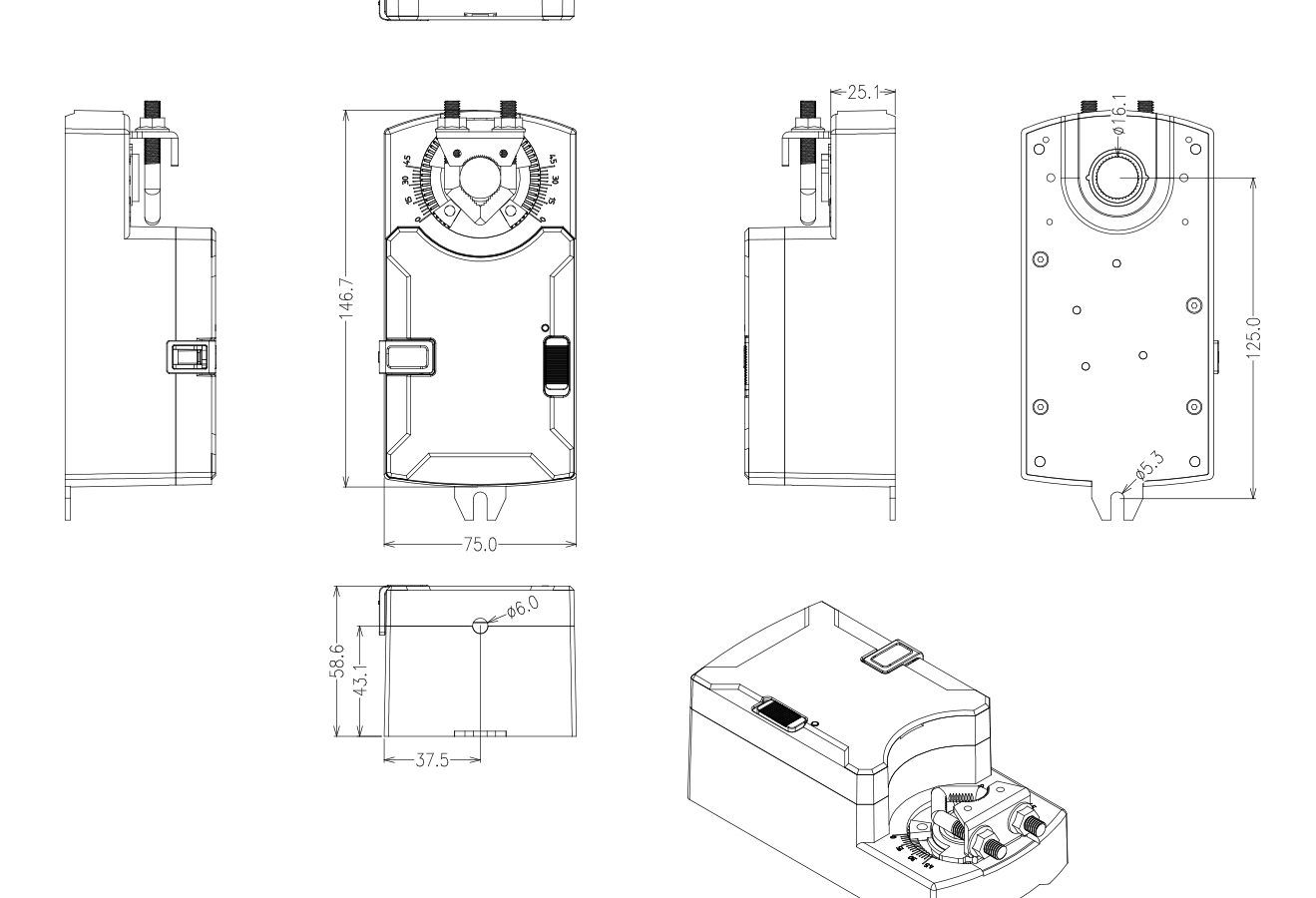
The actuator drawing shows the enclosure, direct-coupled clamp and access needed around the 2 Nm mechanism. Compare the 146.7 x 75 x 58.6 mm envelope and shaft interface with the damper mounting detail before using the full specification table to release the selected configuration.
| Specification | Published Value | Selection Check |
|---|---|---|
| Product configuration | 1S2N / SQRB24-1-ES | Identify this exact configuration on the quotation and submittal |
| Rated torque | 2 Nm | Confirm breakaway and running torque at the highest operating pressure |
| Rated runtime | 1.0 s for 90 degrees at rated load | Do not treat actuator travel as the complete airflow-response time |
| Rated supply | 24 V AC, 50/60 Hz or 24 V DC ±10% | Verify transformer capacity and voltage at the actuator |
| Power | 34 VA / 17 W | Use the source labels separately in the electrical schedule |
| Control input | 0(2)–10 V DC or 0(4)–20 mA | Confirm the ordered input and controller output type |
| Voltage-input impedance | 1 MΩ | Include in the panel I/O review |
| Position feedback | 2–10 V DC, maximum 5 mA | Match the receiving analog input |
| Positioning accuracy | ≤ ±0.5% | Published test method is not stated; verify project acceptance criteria |
| Rotation range | 30–95 degrees adjustable | Set mechanical limits to the actual damper travel |
| Rotation direction | CW or CCW, switch-selectable | Match installed opening and closing direction |
| Stroke setup | Automatic start/end adaptation | Run adaptation after mounting and stop adjustment |
| Shaft interface | 8–16 mm round or 16 × 16 mm square; minimum 25 mm length | Measure the actual shaft before release |
| Overall dimensions | 146.7 × 75 × 58.6 mm | Allow clamp, cable and removal clearance |
| Protection / ambient | IP53; 0 to +50 °C; 10–95% RH non-condensing | Do not assume chemical, washdown or outdoor suitability |
| Connection | 900 mm cable, 4 × 0.68 mm² | Coordinate junction and cable routing |
| Sound / weight | Maximum 52 dB; approximately 720 g | Sound test conditions are not published |
Use the drawing and table as one selection check. The shaft must enter the clamp squarely with at least 25 mm of usable length, the enclosure must clear adjacent components, and access must remain for the clamp, direction switch and cable. The electrical values then determine whether the actuator matches the control panel and required sequence.
Record the required torque, one-second operating sequence, supply, command signal, feedback range, shaft form, available clearance and ambient condition in the quotation request. Final mounting and wiring should follow the approved submittal for the supplied actuator rather than a drawing from another actuator family.
Fast-Acting Modulating Control Overview
What the Actuator Controls
This fast acting damper actuator converts a proportional electrical command into rotary shaft movement. Unlike a two-position actuator that moves only to open or closed, the analog input allows the connected controller to request intermediate damper positions. The 2–10 V feedback output then reports actuator position to a compatible analog input for supervision, sequence logic or commissioning records.
The actuator positions the blade; it does not calculate airflow, room pressure or fume hood face velocity by itself. Those control variables require the appropriate sensor and controller. For a laboratory exhaust branch, for example, the controller may compare measured airflow or face velocity with a target and continuously adjust its analog command to the actuator.
What One-Second Travel Changes
The published 1.0-second runtime applies to a 90-degree actuator movement at rated load. This rapid mechanical response can reduce actuator delay in a control loop where the required airflow state changes quickly, such as a fume hood sash movement, a room supply/exhaust tracking correction or a laboratory exhaust emergency command. It also increases the importance of correct controller tuning because a fast actuator can react to every command change, including unstable or noisy commands.
Selection must therefore consider more than speed. A control sequence needs suitable sensor sampling, command scaling, deadband, filtering and response limits so the actuator does not hunt around the target position. The damper shaft and blade also need sufficient mechanical condition to complete rapid movements repeatedly without binding or striking an incorrectly set stop.
Actuator Runtime Versus System Response
A one-second actuator does not guarantee that airflow, duct pressure, room pressure or face velocity will settle in one second. The connected damper’s flow characteristic, duct volume, fan inertia, sensor location, measurement filtering and controller algorithm all contribute to the observed response. State the required system response separately from the actuator runtime, then confirm it during integrated commissioning.
Where the project requires a documented emergency or life-safety function, actuator speed alone is not sufficient. The complete damper assembly, power-loss behavior, controller sequence, alarm logic and required certification must all be specified and verified.
Analog Input, Position Feedback and Wiring
The control panel must provide both the correct 24 V supply and the analog signal selected for the actuator. Power and signal common should be coordinated in the approved control schematic, and the receiving analog input must be suitable for the 2–10 V feedback output and its published maximum current.
Separate the Command from the Position Feedback
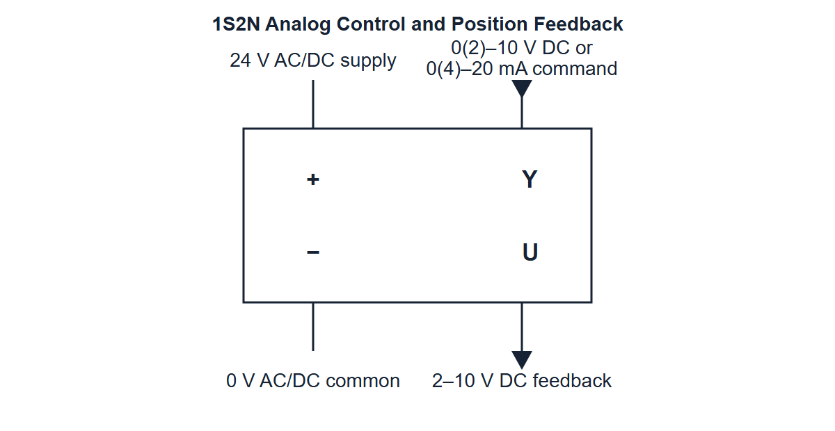
Terminal function Y is the command input. The documented options are 0(2)–10 V DC or 0(4)–20 mA, with a published 1 MΩ impedance for the voltage input. Terminal function U is a 2–10 V DC position-feedback output with a maximum 5 mA load. The feedback reports actuator position; it does not prove damper airflow, leakage or the controlled room condition.
Use the diagram below to confirm the four conductor functions before assigning controller terminals. The diagram shows electrical roles rather than a complete project schematic, so fusing, isolation, grounding, cable segregation and controller-specific commoning still belong in the approved panel design.
| Conductor | Function | Published Signal | Panel Check |
|---|---|---|---|
| Red | Positive supply (+) | 24 V AC/DC | Verify available voltage at the actuator under load |
| Black | Supply common (−) | 0 V AC/DC | Coordinate power and signal common with the controller design |
| White | Control input Y | 0(2)–10 V DC or 0(4)–20 mA | Confirm which input form is ordered and configured |
| Green | Position feedback U | 2–10 V DC, maximum 5 mA | Match receiving analog-input range and impedance |
The wire colors and functions above belong to this verified four-core configuration. Do not reuse a terminal schedule from a communicating, spring-return or slower modulating actuator. Confirm the supplied wiring identification against the approved submittal before energizing the device.
Scale the Analog Signals Before Commissioning
Define how the selected command range maps to the configured mechanical stroke. A 2–10 V command may represent the adjusted minimum and maximum actuator positions rather than an assumed 0–90 degree movement. After the mechanical stops are set and stroke adaptation is completed, verify command points near minimum, midpoint and maximum and compare the feedback signal with the observed actuator position.
If airflow or pressure is the controlled variable, complete a separate functional test using the actual sensor value. Position feedback is useful for actuator diagnostics, but it cannot replace measured process feedback in a closed-loop laboratory ventilation system.
Electrical Inputs Required for the Quotation
- 24 V AC or DC supply and available transformer capacity.
- Required 0–10 V, 2–10 V, 0–20 mA or 4–20 mA command convention.
- Controller/BMS analog-output type and signal common arrangement.
- Receiving analog-input range for the 2–10 V position feedback.
- Required cable length, junction location and panel terminal schedule.
- Normal, minimum, maximum and emergency command sequence.
Direct-Coupled Mounting and Mechanical Fit
The actuator mounts directly to the damper shaft, so torque and shaft geometry must both pass before the product is released. Duct diameter or blade area alone does not establish the required torque; seal friction, bearings, blade construction, pressure difference, contamination and linkage condition can increase the peak load.
Confirm Breakaway and Running Torque
The published rated torque is 2 Nm. Compare this value with the damper manufacturer’s torque requirement or a verified measurement at the highest expected operating pressure. Include the force needed to move away from a closed seal and any increase caused by aging, deposits or misalignment. A shaft that can be turned easily with the damper unpressurized may require more torque under actual service conditions.
Do not select this actuator by runtime if the damper load is uncertain. An undersized fast actuator may fail to reach command, stall near a seal or produce unstable feedback. When the verified requirement exceeds 2 Nm, route the application to a higher-torque fast or standard modulating actuator and confirm the resulting runtime separately.
Match the Shaft and Installation Envelope
The documented clamp accepts an 8–16 mm round shaft or a 16 × 16 mm square shaft, with at least 25 mm of usable shaft length. Measure the shaft at the intended clamp position rather than relying on the nominal damper size. Record flats, shoulders, keyways, coatings and any nearby obstruction that could prevent full engagement.
The enclosure measures 146.7 × 75 × 58.6 mm. Allow additional clearance for the clamp, cable bend, direction switch and future removal. Keep the shaft aligned with the actuator output; forcing the housing sideways to meet a bracket can load the clamp and bearings before the actuator begins to move.
Set Mechanical Limits Before Stroke Adaptation
The rotation range is mechanically adjustable from 30 to 95 degrees. Establish the damper’s true minimum and maximum blade positions first, then set the mechanical stops so the actuator does not drive against the damper body or an external linkage stop. Select clockwise or counterclockwise operation to match the installed opening direction.
Run automatic stroke adaptation only after the shaft clamp and mechanical limits are secure. The adaptation function identifies the configured start and end positions for the analog command range. After adaptation, command several intermediate points and verify smooth movement, physical blade position and feedback scaling. Repeat adaptation if the mechanical limits, actuator orientation or shaft connection changes.
Mechanical Information Required Before Ordering
- Damper type, blade dimensions and intended service.
- Required breakaway and running torque at the design pressure condition.
- Round or square shaft dimensions and usable protruding length.
- Required minimum and maximum blade angle.
- Actuator mounting side and clockwise/counterclockwise opening direction.
- Available enclosure, clamp, cable and maintenance clearance.
Applications and Project Fit
Laboratory Supply and Exhaust dampers
A fast acting damper actuator can be considered where a laboratory supply or exhaust branch must respond quickly to a controller command. The controller may use airflow or pressure feedback to change the actuator position, while the actuator’s own 2–10 V output reports shaft position. Confirm that the 2 Nm torque and shaft interface suit the selected damper under the actual pressure condition.
Fume Hood Exhaust Control
Fume hood systems are a common application for fast actuator movement because a sash change can alter the required exhaust airflow. In this arrangement, a separate face-velocity or airflow controller determines the command; the actuator rapidly positions a compatible exhaust damper. The hood, sensor, controller, damper, fan and commissioning method together determine containment and response performance.
This actuator should not be described as a complete fume hood controller. It does not measure face velocity, calculate the required airflow or provide the user alarm/display functions expected from a hood controller. Those functions belong to the selected control package.
Room Pressure and Supply/Exhaust Tracking
Rapid modulating actuation may support rooms where supply and exhaust flows are adjusted to maintain a planned offset or pressure relationship. The project must define which controller owns the sequence, where airflow or differential-pressure sensors are located, how opposing dampers or valves coordinate, and how stable operation is maintained during door, sash or fan changes.
Applications That Require Another Product or Additional Approval
- Fire and smoke control dampers requiring a listed actuator/damper assembly.
- Power-loss return duties requiring a documented spring-return or certified fail-safe mechanism.
- Dampers requiring more than 2 Nm torque.
- Outdoor, washdown, condensing or chemically aggressive locations not covered by the published IP53 and ambient data.
- Projects requiring actuator-level RS-485 or Modbus communication.
- Two-position duties that do not need proportional control or position feedback.
For corrosive exhaust, review the location of the actuator relative to the contaminated air stream and confirm enclosure, shaft, bracket and cable suitability for the actual chemicals. The published IP53 rating does not by itself establish chemical resistance.
How to Select and Specify a Fast-Acting Damper actuator
1. Define the Controlled Variable and Sequence
State whether the controller is regulating airflow, duct pressure, room pressure, fume hood face velocity or another measured variable. Record the minimum, normal, maximum and emergency operating states and identify what event changes the command. This determines whether one-second actuator travel is technically useful and how the controller should be tuned.
2. Verify the Required Torque
Obtain the damper manufacturer’s requirement or measure the actual breakaway and running torque under the design pressure condition. Compare the highest credible load with the actuator’s 2 Nm rating. Include seals, bearings, contamination and long-idle friction; do not reserve all margin for nominal blade area.
3. Separate Actuator Runtime from Required System Response
Specify the actuator requirement as 1.0-second travel through 90 degrees at rated load. Specify airflow, pressure or face-velocity response as a separate system criterion with its own tolerance, settling definition and test method. This prevents a component runtime from being mistaken for a complete control-loop guarantee.
4. Match Power, Command and Feedback
Confirm 24 V AC/DC supply capacity, then select the required voltage or current command convention. Record the controller output, common arrangement and receiving input for the 2–10 V position feedback. If the project requires network communication directly at the actuator, route the selection to a communicating product instead of adding an unverified interface.
5. Close the Mechanical Interface
Provide a shaft drawing or measured photograph showing cross-section, dimensions and usable length. Confirm the rotation range, opening direction, actuator mounting side and available envelope. The actuator should be selected only when the 8–16 mm round or 16 × 16 mm square clamp and the minimum 25 mm engagement suit the actual damper.
6. Define Power-Loss and Safety Behavior
State the required blade position during loss of power, controller failure and loss of measurement. This configuration uses electronic reset, but no mechanical spring-return direction or certified fail-safe function is specified. When a defined de-energized position is mandatory, specify the required mechanism and certification explicitly and select the corresponding actuator family.
7. Review Environment and Acceptance
Compare the installation with the published IP53 rating, 0 to +50 °C operating range and non-condensing humidity condition. Define the tests that will confirm command scaling, travel, feedback, airflow or pressure response, alarms and fallback behavior after installation.
Quotation and Submittal Checklist
- Application, damper type, blade size and service.
- Breakaway/running torque and design pressure condition.
- Shaft size, shape, usable length and mounting orientation.
- Required stroke, opening direction and 1-second runtime requirement.
- 24 V supply, analog command range and feedback input.
- Controller, sensor, BMS points and control sequence.
- Normal, power-loss and emergency positions.
- Ambient temperature, humidity, chemical exposure and enclosure requirements.
- Quantity, destination, drawings and documentation requirements.
The returned submittal should identify the proposed actuator configuration, supplied cable and mounting scope, applicable performance values, unresolved project conditions and commissioning responsibilities. Those approved fields define the delivered product.
Installation and Commissioning
Commission the actuator as part of the complete damper and control loop. Mechanical freedom and correct shaft engagement must be established before a rapid electrical movement is commanded.
Mechanical Installation
- Isolate power and move the damper manually through its required range.
- Correct binding, damaged bearings, shaft misalignment or blade interference before fitting the actuator.
- Confirm the shaft shape, dimensions and minimum 25 mm usable engagement.
- Align the actuator and damper to corresponding positions, secure the clamp and restrain the actuator body.
- Set the mechanical minimum and maximum stops without forcing the blade against the damper body.
- Check enclosure, cable and maintenance clearance in the final mounting orientation.
Electrical Connection and Initial Setup
- Verify the actuator identification, 24 V supply and approved four-conductor wiring schedule.
- Connect the selected analog command to Y and the 2–10 V position feedback from U to a compatible input.
- Select clockwise or counterclockwise operation to match the installed blade sequence.
- Energize the unit with the controller output held at a known safe command.
- Run stroke adaptation after the mechanical stops and shaft clamp are final.
Travel and Feedback Verification
Command the configured minimum, midpoint and maximum positions. Verify smooth movement, mechanical indicator position and the corresponding feedback voltage. The actuator should reach each point without striking a stop, moving the housing or loosening the clamp. Confirm the rated-time requirement under the actual connected load rather than with the actuator disconnected from the damper.
Integrated System Acceptance
Operate the real control sequence and trend the controlled variable, command and position feedback together. Check normal changes and the most demanding transition, including sash movement, supply/exhaust tracking or pressure correction as applicable. Verify stable settling without hunting, required alarms, controller fallback and the defined response to power or signal loss.
Position feedback confirms actuator movement only. Final acceptance for a laboratory system must use the actual airflow, pressure or face-velocity measurement and the project’s specified test method.
Frequently Asked Questions
What makes this a fast acting damper actuator?
The verified configuration completes a 90-degree movement in 1.0 second at rated load and provides 2 Nm rated torque. Compare runtime only under its stated load and travel condition; a faster unloaded movement is not an equivalent rating.
Is this an on/off actuator?
No. This product accepts a proportional analog command and can position the damper between its configured minimum and maximum. Use a two-position or on/off actuator when the sequence requires only fully open and fully closed states.
Does one-second actuator travel mean the airflow responds in one second?
No. Actuator runtime describes shaft movement. Airflow, duct pressure, room pressure or face velocity also depends on the damper, duct, fan, sensor and controller. Specify and test the complete system response separately.
Is the actuator spring return or fail safe?
No mechanical spring-return direction or certified fail-safe function is specified for this configuration. It uses electronic reset, but the required blade position during power loss must be defined and verified for the project. Select a documented spring-return or listed safety actuator when that behavior is mandatory.
What does the 2–10 V feedback signal confirm?
The U output reports actuator position to a compatible analog input. It can support diagnostics and position verification, but it does not directly confirm airflow, damper leakage, pressure or fume hood containment.
Can it be installed on an existing ventilation damper?
It can be evaluated when the existing damper requires no more than 2 Nm and has an 8–16 mm round shaft or a 16 × 16 mm square shaft with at least 25 mm usable length. Mounting clearance, blade travel, rotation direction and control signals must also match.
What information should be provided before ordering?
Send the damper drawing, shaft dimensions, required torque, pressure condition, rotation range, desired runtime, 24 V supply, analog command and feedback details, control sequence, power-loss position, environment, quantity and destination. Include the airflow, pressure or face-velocity targets when the actuator is part of a laboratory control loop.
Contact the Xicheng Engineering Team Today.
Send the damper drawing, shaft dimensions, required torque, design pressure, rotation range, 24 V supply, analog command and feedback signals, control sequence, required system response, power-loss position, operating environment, quantity, and destination. XICHENG will review the actuator fit and return the applicable configuration, mounting and wiring information, unresolved technical items, supplied scope, documentation, and commercial pricing.
Shenzhen Office: No. 34 Zhenxing Road (Shengtaian Heavy Industrial Park B), Loucun, Guangming New District, Shenzhen, Guangdong, China
WhatsApp: +86 181 2647 8161
Engineering Mailbox: fanalax34@gmail.com