


Description
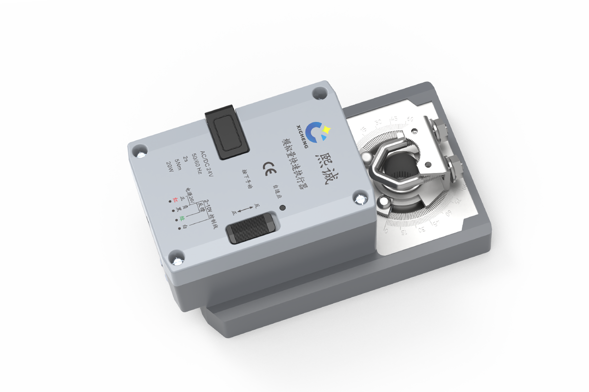
A fast modulating damper actuator converts a proportional command into rapid quarter-turn movement for laboratory supply, exhaust, fume hood, or pressure-control dampers. Available configurations cover 5-30 Nm torque and 2-15 second travel, allowing response and mechanical load to be selected together. Within XICHENG’s laboratory airflow controls and actuators range, this family covers fast rotary duties that exceed the torque of the compact 1-second actuator.
The range is intended for fume hood exhaust, laboratory supply and exhaust tracking, VAV terminals and other ventilation branches where a conventional slow actuator cannot reposition the damper quickly enough for the required control sequence. Available models support different torque, runtime, enclosure, shaft and signal combinations, so the fastest unit is not automatically the correct unit.
The actuator controls damper position. It does not measure airflow, face velocity, duct pressure or room pressure, and its position-feedback output is not proof of delivered airflow. Complete system response still depends on the damper, sensor, controller, duct pressure, fan or VFD response, control logic and field commissioning.
Product Selection Summary
Choose This Fast Modulating Actuator When
Place this product family on the technical shortlist when the controlled device uses a rotary shaft, requires proportional rather than two-position movement, and must complete the selected angular travel in 2 to 15 seconds. The project should already be able to define damper torque, shaft geometry, command and feedback signals, supply voltage and the required normal and emergency sequence.
- The damper must follow a continuously variable 0-10 V, 2-10 V, 0/4-20 mA or corresponding model-specific command.
- The required torque can be matched to a documented 4, 5, 10, 15 or 30 Nm configuration with the project’s approved design allowance.
- The required 90-degree runtime is 2, 3, 5, 7, 9 or 15 seconds rather than the separate one-second or standard-speed actuator range.
- A 2-10 V or model-specific 0-10 V actuator-position signal is suitable for movement verification.
- The damper has a compatible round or square shaft and at least 40 mm of usable engagement length.
Key Product-Family Data
All listed configurations use AC/DC 24 V power, direct rotary coupling, adjustable 30-95 degree travel, clockwise or counter-clockwise selection and automatic travel adaptation. The compact QRC/D/E range covers 3, 7 and 15-second variants. SQRD-24-2 provides the two-second option, while QRG/J-24-5/9 covers higher-torque 5 and 9-second variants. These are separate configurations, not selectable speed or torque settings on one universal actuator.
Do Not Select from Runtime Alone
Runtime is only one part of the decision. A two-second actuator that cannot overcome the damper’s breakaway torque is not suitable, while a 30 Nm actuator may be unnecessarily large for a small low-friction blade. The selected actuator must also fit the shaft, mounting plane and available clearance, accept the controller output, provide the required feedback, and operate within the available 24 V power capacity.
Fast actuator travel is not the same as complete airflow-control response. Sensor filtering, controller tuning, damper authority, duct pressure and fan behavior can make the measured system respond more slowly than the motor. Projects that require a defined power-loss position must also specify that behavior separately because the documented configurations do not establish a universal spring-return function.
Information Required for a Project-Ready Quotation
Provide the damper tag, blade arrangement and size, calculated breakaway and running torque, shaft shape and dimensions, required movement angle and runtime, AC or DC 24 V supply, command and feedback ranges, normal and emergency sequence, controller or BMS interface, installation orientation, operating environment, quantity and destination. Include the damper drawing, controls schematic and point list when available.
The quotation should identify the proposed actuator configuration, applicable torque and runtime, shaft and mounting arrangement, electrical interface, supplied cable or accessories, operating limits, unresolved technical items and the drawing or wiring document used for approval.
Key Specifications and Model Comparison
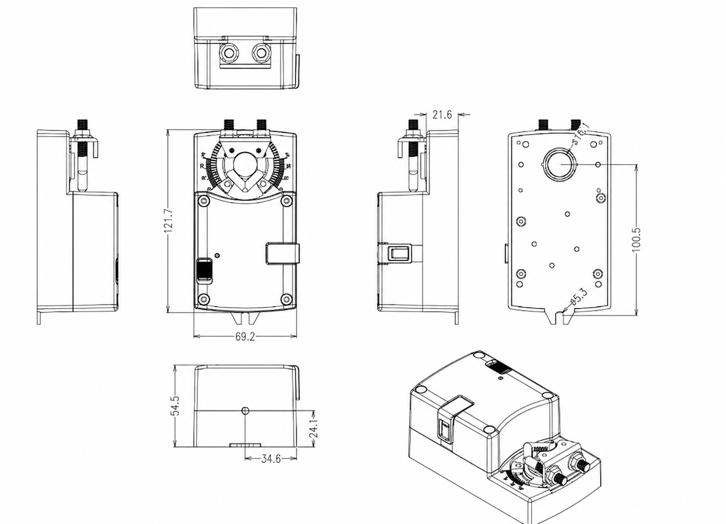
The available fast modulating damper actuators use three enclosure and torque groups. First check the compact QRC/D/E mounting envelope shown below, then compare every shortlisted configuration by torque, runtime, shaft, control signal and power. Values separated by slashes identify corresponding model variants; they are not field-selectable settings on every unit.
| Model Family | Torque / Runtime | Control / Feedback | Mechanical and Electrical Fit |
|---|---|---|---|
| SQRD-24-2 | More than 5 Nm; 2 s per 90 degrees | 2-10 V or 4-20 mA command; 2-10 V feedback | 148 x 84 x 71.5 mm; 8-15 mm round or 10 x 10 mm square shaft; 22 W running |
| QRC/D/E-24-3 | More than 4 Nm; 3 s per 90 degrees | 0-10 V, 2-10 V, 0/4-20 mA or resistive input by version; 0-10 V or 2-10 V feedback | 121.7 x 69.2 x 54.5 mm; 12-15 mm round or 10 x 10 mm square shaft; 7 W running |
| QRG/J-24-5 | More than 15 Nm; 5 s per 90 degrees | 2-10 V or 4-20 mA command; 2-10 V feedback | 158.1 x 84 x 75.5 mm; 8-15 mm round or 10 x 10 mm square shaft; 22 W running |
| QRC/D/E-24-7 | More than 5 Nm; 7 s per 90 degrees | 0-10 V, 2-10 V, 0/4-20 mA or resistive input by version; 0-10 V or 2-10 V feedback | 121.7 x 69.2 x 54.5 mm; 12-15 mm round or 10 x 10 mm square shaft; 7 W running |
| QRG/J-24-9 | More than 30 Nm; 9 s per 90 degrees | 2-10 V or 4-20 mA command; 2-10 V feedback | 158.1 x 84 x 75.5 mm; 8-15 mm round or 10 x 10 mm square shaft; 22 W running |
| QRC/D/E-24-15 | More than 10 Nm; 15 s per 90 degrees | 0-10 V, 2-10 V, 0/4-20 mA or resistive input by version; 0-10 V or 2-10 V feedback | 121.7 x 69.2 x 54.5 mm; 12-15 mm round or 10 x 10 mm square shaft; 7 W running |
For a QRC/D/E configuration, allow for the 121.7 x 69.2 x 54.5 mm enclosure plus cable and service clearance, and match a 12-15 mm round or 10 x 10 mm square shaft with at least 40 mm usable length. Check clamp access, bearing projection, insulation and nearby linkage before approving direct mounting. SQRD and QRG/J use different enclosures, so their selected-model drawings must replace the compact reference during final coordination.
Shared Configuration Data
The listed models use AC/DC 24 V power, maximum adjustable travel of approximately 95 degrees, minimum adjustable travel of approximately 30 degrees, clockwise or counter-clockwise direction selection, mechanical position indication and push-button adaptation of the configured travel. Rated holding consumption is 0.5 W. The operating range is 0 to +50 degrees C at 10-95% RH, non-condensing, with storage from -20 to +50 degrees C.
Model-Specific Limits
QRC/D/E uses an 800 mm five-core cable and has rated position accuracy better than +/-1%. SQRD and QRG/J use a 600 mm four-core cable and list accuracy better than +/-0.5%. Rated sound level is a maximum of 52 dB. Do not transfer one enclosure’s dimensions, cable assignment or shaft range to another model group.
Input impedance varies by QRC/D/E version and must be confirmed on the approved model sheet. The listed CE/EMC reference does not establish a fire/smoke listing, plenum approval, ingress-protection rating, chemical-resistance rating or universal spring-return function.
Modulating Control, Wiring and Position Feedback
The actuator must be ordered and wired for the controller’s actual output convention. Voltage, current and resistive commands are not interchangeable without the correct actuator version and controller setup. Likewise, the position-feedback range must be scaled in the controller or BMS so the reported voltage corresponds to the configured mechanical travel.
Command Signal Options
SQRD and QRG/J configurations accept a DC 2-10 V or 4-20 mA command and provide DC 2-10 V position feedback. QRC/D/E configurations can be supplied for DC 0-10 V, 2-10 V, 0-20 mA, 4-20 mA or a resistive command, with DC 0-10 V or 2-10 V feedback by version. The selected controller output, actuator input and software scaling must use the same range.
Five-Core QRC/D/E Connection Logic
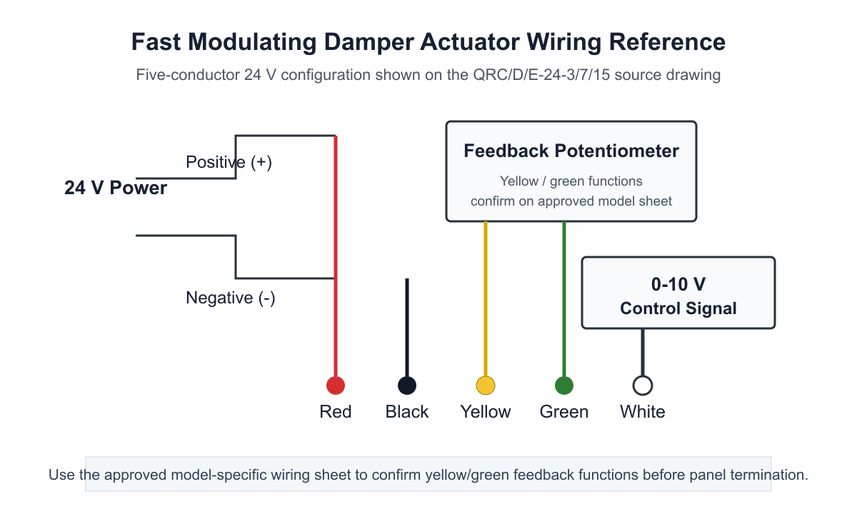
For the five-core QRC/D/E arrangement shown below, red and black supply AC/DC 24 V power, white carries the analog command, and yellow/green form the position-feedback circuit. The exact yellow/green assignment must follow the approved model sheet because feedback conventions vary by version. Keep signal references and power common consistent with the controller design, and do not energize a signal conductor as a supply lead.
| Circuit Function | QRC/D/E Five-Core | SQRD / QRG/J Four-Core | Panel Check |
|---|---|---|---|
| 24 V positive / line | Red | Follow the selected four-core model diagram | Confirm AC or DC supply and transformer capacity |
| 24 V common / neutral | Black | Follow the selected four-core model diagram | Coordinate the power and signal reference |
| Modulating command | White; range depends on ordered version | 2-10 V or 4-20 mA by version | Match controller output type and scaling |
| Position feedback | Yellow/green circuit; confirm exact assignment | 2-10 V, maximum 5 mA | Use as position verification, not airflow measurement |
| Cable | 800 mm, 5 x 0.75 mm2 | 600 mm, 4 x 0.75 mm2 | Provide junction and service access where extension is required |
Use the figure and schedule as one panel-design reference. The table also distinguishes the four-core SQRD/QRG/J arrangement so the QRC/D/E conductor colors are not copied into a different actuator enclosure. Final polarity, common-reference and feedback assignments must follow the selected model sheet.
What Position Feedback Confirms
Position feedback indicates that the actuator moved toward the commanded angular position. It can support trend display, movement alarms and commissioning checks, but it cannot confirm airflow, face velocity, duct pressure or room pressure. Where those variables define safety or performance, use the appropriate sensor and verify the complete loop under actual operating conditions.
Power-Loss and Signal-Loss Sequence
The listed configurations do not establish one universal spring-return or fail-safe behavior. The controls schedule must define what happens after loss of power, loss of command, loss of feedback or communication elsewhere in the system. If mechanical return without normal power is required, evaluate a verified spring-return actuator rather than assuming the fast modulating actuator will drive to a safe position.
Fast Runtime and Complete System Response
Actuator Travel Time
The 2, 3, 5, 7, 9 and 15-second values describe the time for the selected actuator to rotate through 90 degrees under its rated condition. They allow a controls designer to compare motor movement with the required sequence, but they do not guarantee that measured airflow or room pressure will settle within the same interval.
Why the Airflow Loop May Respond More Slowly
After the actuator moves, the damper must change the effective opening, the branch pressure must redistribute, the fan or VFD may need to react, and the airflow or pressure sensor must detect the result. Controller filtering, network updates and loop tuning add further delay. A fast actuator can remove one source of lag, but it cannot overcome an undersized fan, unstable damper authority, poor sensor placement or an unsuitable control sequence.
Torque and Runtime Trade-Off
Faster movement is useful only when the actuator can reliably move the actual damper. The available family pairs different runtimes with different torque capacities: the compact group covers 4-10 Nm, the two-second model exceeds 5 Nm, and the larger 5/9-second group exceeds 15 or 30 Nm. Determine breakaway torque at the operating pressure, account for seals, bearings, linkage and aging, then apply the project-approved allowance before selecting speed.
Control Stability Review
Very rapid shaft movement can produce hunting if the sensor and controller are tuned for a much slower mechanical device. During commissioning, verify command direction, feedback scaling, dead band, gain, integral action, sensor filtering and any minimum movement interval. Test normal modulation and the fastest expected demand change rather than accepting a no-load bench movement as complete system proof.
Direct-Coupled Mounting and Mechanical Fit
Shaft Shape, Diameter and Engagement
QRC/D/E configurations fit 12-15 mm round shafts or 10 x 10 mm square shafts. SQRD and QRG/J configurations fit 8-15 mm round shafts or 10 x 10 mm square shafts. Each group requires at least 40 mm of usable exposed shaft. Measure the actual shaft after accounting for bearings, shoulders, insulation, blade linkage and the mounting bracket.
Enclosure and Service Clearance
The compact QRC/D/E enclosure measures 121.7 x 69.2 x 54.5 mm, SQRD measures 148 x 84 x 71.5 mm, and QRG/J measures 158.1 x 84 x 75.5 mm. These dimensions do not include every possible cable bend, connector, tool movement or access requirement. Leave room to release the shaft clamp, operate the adaptation control, view the position indicator and service the wiring without removing adjacent ductwork.
Rotation and Working Angle
The working angle can be adjusted from approximately 30 to 95 degrees, with clockwise or counter-clockwise direction selected to match the damper. Before tightening the clamp, place the damper blade and actuator at corresponding reference positions. A reversed direction or offset starting angle can drive the blade into a mechanical stop even when the electrical command appears correct.
Damper Torque Verification
Use the damper manufacturer’s torque data or a documented field measurement at the maximum expected differential pressure. Include breakaway friction, blade seals, bearings, linkage, contamination and installation tolerance. Do not infer damper suitability from shaft diameter alone. The actuator must move the complete blade assembly through its required angle without binding and without relying on the actuator as the damper’s mechanical stop.
Installation Environment
The listed operating condition is 0 to +50 degrees C and 10-95% relative humidity without condensation. For laboratory exhaust, verify whether the actuator remains outside the contaminated airstream and whether condensation, washdown, outdoor exposure or corrosive vapor can reach the enclosure or shaft. Request a specific enclosure and material review when the installation exceeds the stated environment.
Applications and Project Fit
Fume Hood Exhaust Control
A fast modulating damper actuator can drive a compatible rotary exhaust damper in a fume hood VAV system when the hood controller requires rapid proportional blade movement. The actuator must be selected with the hood’s airflow range, damper torque, shaft interface, available duct pressure and face-velocity control sequence. Position feedback can confirm actuator movement, while a face-velocity or airflow sensor closes the actual safety and performance loop.
Laboratory Supply and Exhaust Tracking
Laboratory rooms may require supply and exhaust dampers to follow changing hood demand while maintaining the specified room offset. A fast actuator can reduce mechanical delay in the branch, but room-pressure stability still depends on the controller strategy, sensor location, fan response, minimum airflow settings and interaction among multiple terminals. Select the runtime as part of the complete tracking sequence.
VAV Terminals and General Ventilation Branches
The same actuator family can serve compatible VAV terminal dampers, make-up air branches and process-ventilation dampers that use a rotary shaft and analog command. Confirm torque at the actual pressure condition and make sure the controller can use the selected voltage or current input and feedback. Applications with slow thermal demand may not benefit from the fastest runtime and may be better served by a standard modulating actuator.
Applications Requiring Another Product
Use an On/Off Direct-Coupled Damper actuator when the damper only needs open/close positioning. Evaluate a Spring-Return Damper actuator when loss of power must mechanically drive the shaft to a defined position, a Communicating Modulating Damper actuator when the actuator itself requires an RS-485/Modbus interface, and a Linear-Stroke Damper actuator when the controlled mechanism needs push-pull movement.
Do not use this family as a fire damper actuator, smoke damper actuator, explosion-proof actuator, outdoor actuator or corrosion-rated actuator unless the exact supplied model has the required construction and project approval. Those functions cannot be inferred from fast runtime or 24 V operation.
How to Select and Specify a Fast Modulating Damper actuator
1. Define the Controlled Damper
Record the damper type, blade arrangement, dimensions, shaft shape and size, usable shaft length, direction of rotation and required working angle. Confirm whether the actuator mounts directly to the shaft or requires a bracket or linkage. The actuator page cannot define damper airflow, leakage or pressure-drop performance.
2. Establish Required Torque
Use the maximum breakaway and running torque at the design differential pressure, including seals, bearings, linkage and the project’s approved allowance. Select only from configurations that meet the resulting requirement. Do not reduce the torque requirement to obtain a faster model.
3. Choose the Required Runtime
Compare the 2, 3, 5, 7, 9 and 15-second options with the required control sequence and complete loop response. Faster is useful when rapid repositioning is necessary and the controller can remain stable. A slower high-torque model may be the correct choice for a larger damper or a sequence that does not need one- or two-second movement.
4. Match Power, Command and Feedback
Confirm AC or DC 24 V power, transformer or supply capacity, command type, feedback type, signal common and cable requirements. Specify the exact range rather than writing only “analog.” The controls schedule should state how 0 or 2 V and 10 V map to the installed damper positions and how signal loss is handled.
5. Define Normal and Failure Behavior
State the required position during normal modulation, emergency exhaust, standby, power loss, command loss and controller fault. If a mechanical return position is mandatory, use a verified spring-return configuration. If an actuator network interface is mandatory, select the corresponding communicating product rather than adding an unsupported protocol to this family.
6. Confirm Mounting and Environment
Check the model-specific enclosure, shaft interface, 40 mm engagement length, cable routing, service clearance, temperature, humidity and exposure. For laboratory exhaust, identify any corrosive vapor, condensation or washdown risk and state whether the actuator is isolated from the airstream.
Suggested Specification Schedule
For each tag, list product type, actuator configuration, torque, 90-degree runtime, working angle, direction, supply, power consumption, command range, feedback range, cable, shaft interface, mounting arrangement, operating environment, normal/emergency/failure sequence, controller or BMS interface, supplied accessories and required approval documents. The quotation and approved model sheet should identify the exact delivered combination.
Installation and Commissioning
Pre-Installation Checks
- Verify the actuator label, torque, runtime, supply and signal version against the approved tag schedule.
- Move the damper manually through its intended range and correct binding, misalignment or excessive seal friction.
- Measure the shaft shape, size and usable length, then confirm the selected clamp and mounting plane.
- Check enclosure, cable and tool clearance before drilling or tightening the mounting hardware.
- Isolate electrical power and follow the project lockout procedure.
Mechanical Installation
Place the damper and actuator at corresponding reference positions, engage the clamp over the required shaft length and secure the anti-rotation or mounting arrangement without distorting the enclosure. Set the mechanical working angle to the required blade travel. The damper’s own stops should define its physical range; do not use actuator stall torque to force the blade beyond those limits.
Electrical Connection and Travel Adaptation
Connect AC/DC 24 V power, analog command and position feedback according to the exact model diagram. Confirm polarity and common references for DC circuits and verify that controller outputs are configured for voltage, current or resistive operation as ordered. After mechanical alignment, run the adaptation procedure so the actuator records the installed start and end positions.
Functional Commissioning
Command several intermediate positions and compare the actuator indicator and feedback signal with the requested value. Then test minimum, normal, maximum and emergency system states under actual fan operation. Confirm rotation direction, stable modulation, acceptable measured airflow or pressure response, alarm logic and the specified reaction to command, feedback or power loss.
Acceptance Records
Record the final actuator model, damper tag, shaft and mounting arrangement, configured angle, command and feedback scaling, measured runtime, sensor readings, controller settings, alarm tests and unresolved items. Retain the approved model sheet, wiring diagram and commissioning results with the system handover documents.
Frequently Asked Questions
What makes this a fast modulating damper actuator?
It accepts a continuously variable analog command and moves a compatible rotary damper through 90 degrees in a selected 2, 3, 5, 7, 9 or 15-second configuration. The exact runtime is tied to a specific torque and enclosure; it is not a universal speed setting.
Which torque and runtime should be selected?
Determine damper breakaway and running torque at the maximum operating pressure, include seals, bearings, linkage and the project-approved allowance, then select from models that meet that torque. Choose the runtime that supports the complete control sequence without destabilizing the airflow or pressure loop.
Can the actuator use both voltage and current commands?
Available inputs depend on the ordered version. QRC/D/E can be configured for 0-10 V, 2-10 V, 0-20 mA, 4-20 mA or a resistive input. SQRD and QRG/J use 2-10 V or 4-20 mA versions. Confirm one exact input and feedback convention on the approved model sheet.
Does position feedback confirm airflow?
No. Position feedback reports actuator movement or angular position. Measured airflow, face velocity, duct pressure or room pressure requires the appropriate sensor and commissioning test.
Can this actuator be used in a fume hood VAV system?
Yes, when the actuator is matched to the hood exhaust damper, torque, shaft, controller signal, airflow schedule, available pressure and required response. It remains one component of the system and does not replace the face-velocity sensor, airflow controller, fan, balancing or containment verification.
Does the actuator return to a safe position when power is lost?
The listed 2-15 second family does not establish one universal mechanical spring-return function. Define the required power-loss position and select a verified spring-return actuator when mechanical return without normal power is mandatory.
What shaft sizes are supported?
QRC/D/E supports 12-15 mm round or 10 x 10 mm square shafts. SQRD and QRG/J support 8-15 mm round or 10 x 10 mm square shafts. All listed groups require at least 40 mm of usable shaft length, plus suitable mounting and service clearance.
What information is required for quotation?
Provide the damper tag, type and size, torque calculation, shaft dimensions, required working angle and runtime, 24 V supply, command and feedback ranges, normal/emergency/failure sequence, controller or BMS interface, installation environment, drawings, quantity and destination.
Contact the Xicheng Engineering Team Today.
Send the damper schedule, torque calculation, shaft dimensions, required 90-degree runtime, AC/DC 24 V supply, command and feedback signals, normal and failure sequence, controller information, installation drawing, quantity and destination. XICHENG will return a proposed fast modulating damper actuator configuration, applicable specifications, mounting and wiring scope, unresolved technical items and commercial pricing.
🎯 Shenzhen Office: No. 34 Zhenxing Road (Shengtaian Heavy Industrial Park B), Loucun, Guangming New Dist, Shenzhen, Guangdong, China
☎️ WhatsApp: +86 181 2647 8161
📬 Engineering Mailbox: fanalax34@gmail.com