


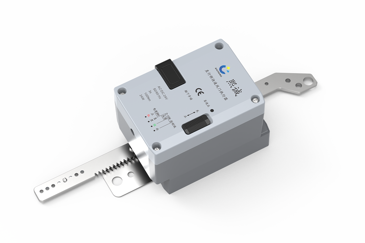
Description
This linear damper actuator moves a laboratory VAV damper or air-valve mechanism through a straight push-pull linkage instead of rotating a shaft. It provides 100 N force, an adjustable 10-100 mm stroke, and approximately 3-second travel at the full stroke. It is the linear-motion option within XICHENG’s laboratory airflow controls and actuators range and must be selected from the actual linkage geometry, required force, usable stroke, and control signal.
The actuator uses AC/DC 24 V power and accepts a proportional analog command. A 2-10 V or 4-20 mA input is selected by configuration, while a 2-10 V output reports the mapped linear position. Mechanical stroke adjustment and endpoint adaptation allow the electrical signal to be matched to the installed linkage travel.
This product moves the mechanism; it does not determine the required airflow, compensate for an undersized fan or measure pressure, face velocity or air volume. A compatible controller or signal source must generate the demand. The connected valve or damper, linkage and installation must also remain within the actuator’s force and travel limits throughout every operating mode.
Product Selection Summary
This linear stroke damper actuator is a good fit when the controlled mechanism requires rapid straight-line movement rather than rotary torque. Confirm the required force, usable stroke, linkage geometry, response time, analog signal and failure sequence before assigning it to a valve or damper.
Choose This Product When
- The valve, damper or airflow-control mechanism is operated by a push-pull linkage or sliding element.
- The complete mechanism requires no more than the available 100 N force across its full installed travel.
- The selected movement can be set between 10 and 100 mm and a 100 mm stroke must complete in approximately 3 seconds.
- AC/DC 24 V power is available and the controller can provide the selected 2-10 V or 4-20 mA demand.
- A 2-10 V linear-position signal is suitable for position monitoring, with airflow or pressure measured separately when required.
Key Product Data
The actuator provides 100 N rated force, 10-100 mm mechanically adjustable stroke and 3-second travel at the 100 mm condition. It uses a 243.5 x 64.6 x 72.4 mm enclosure and linkage assembly, consumes 55 W while running and 0.5 W while holding, and is supplied with a 60 cm four-core cable. Direction is switch-selectable and the adaptation function maps the installed endpoints.
Choose Another Actuator When
Use a fast modulating rotary damper actuator when the device must turn a shaft rather than move a linkage in a straight line. Use the standard modulating damper actuator when 30- to 120-second rotary travel is acceptable, or the spring-return damper actuator when a documented mechanical return action is required after power loss. This linear product has no documented spring-return or network-communication function.
Information Needed for a Useful Quotation
Provide the controlled device and application, required push and pull force, selected stroke, complete linkage drawing, mounting-hole geometry, alignment and clearance, required response, AC/DC 24 V supply, 2-10 V or 4-20 mA command, 2-10 V feedback, normal movement direction, power-loss and lost-signal sequence, controller or sensor, quantity and destination. These values determine whether the actuator can be applied without overtravel, side loading or an incompatible electrical interface.
Linear Damper actuator Specifications and Mechanical Envelope
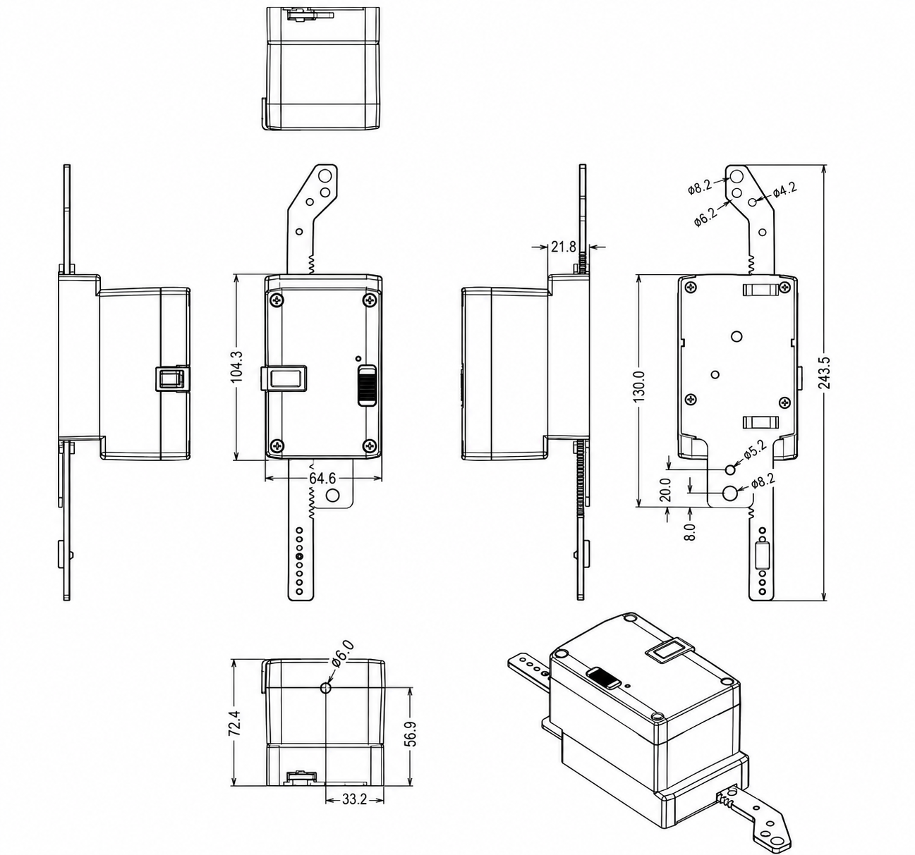
The dimension drawing should be checked before the control signal is finalized. The actuator body, two linkage arms, mounting holes and moving rack require more installation space than the enclosure width alone suggests. Confirm the selected attachment points and available movement path against the controlled device drawing.
Check These Fit Conditions
- Allow for the complete 243.5 mm linkage envelope, not only the 104.3 mm body section.
- Select attachment holes that produce the required effective 10-100 mm travel without overtravel.
- Keep both linkage lines aligned with the controlled mechanism to avoid side load and binding.
- Leave access to the enclosure, direction switch, adaptation control, cable and fasteners.
The drawing establishes where the actuator can be mounted, but it does not prove that the connected mechanism requires less than 100 N. Check force separately at startup, through the middle of travel and near both endpoints, where seals, springs or linkage angles can increase the load.
Product Specification Table
| Specification | Product Data | Selection Check |
|---|---|---|
| Product type | Fast analog linear damper actuator | For straight push-pull movement |
| Sheet model | SQL24-R100-3 | Use the supplied model on the final schedule |
| Configuration notation | 3S100N | 3-second / 100 N configuration |
| Rated force | 100 N at rated voltage | Check full-stroke mechanism load |
| Adjustable stroke | 10-100 mm by mechanical setting | Match effective linkage movement |
| Rated travel time | 3 seconds at 100 mm stroke | Keep speed tied to stroke condition |
| Rated supply | AC 24 V, 50/60 Hz or DC 24 V, +/-10% | Check transformer and voltage drop |
| Power consumption | 55 W running; 0.5 W holding | Size for simultaneous movement |
| Control input | DC 2-10 V or 4-20 mA by configuration | Order the controller-compatible version |
| Position feedback | DC 2-10 V, maximum 5 mA | Position only, not airflow measurement |
| Positioning accuracy | Better than +/-0.5% at 100 mm stroke | Do not convert to system airflow accuracy |
| Movement direction | Selectable by switch | Confirm extend/retract mapping |
| Cable connection | 60 cm cable, 4 x 0.75 mm2 | Confirm routing and termination |
| Overall dimensions | 243.5 x 64.6 x 72.4 mm | Include linkage and service clearance |
| Operating environment | 0 to +50 C; 10-95% RH, non-condensing | Other enclosure ratings are not stated |
| Sound level | Maximum 52 dB | Test condition is not stated |
| Weight | Approximately 750 g | Actuator assembly |
Force, Stroke and Speed Must Be Checked Together
The three headline values solve different parts of the selection. Force determines whether the actuator can move the mechanism; stroke determines whether its travel reaches the required positions; speed determines whether the complete movement meets the operating sequence. A 100 mm linkage that needs more than 100 N is not suitable even when the response time is correct, and a mechanism that needs only 30 mm should be limited and adapted to that travel rather than driven beyond its safe range.
Analog Control and Linear-Position Feedback
The actuator converts a proportional command into a position along the selected linear stroke. At one end of the command range the linkage moves toward its configured start point; at the other end it moves toward the configured finish point. The direction switch defines which physical movement follows an increasing signal, and the adaptation routine scales the electrical range across the installed endpoints.
Select the Correct Command Version
DC 2-10 V and 4-20 mA control are available by configuration. These are alternative input versions, not proof that every unit accepts both signals on the same conductors. The controller output and actuator input must use the same range and common-reference arrangement. State the required signal on the equipment schedule and confirm it again against the supplied wiring diagram before termination.
2-10 V Wiring Example
The four-conductor diagram below applies to the 2-10 V linear actuator configuration. Red and black provide 24 V power, white carries the 2-10 V command and green returns the 2-10 V linear-position signal. Check controller and actuator commons, transformer capacity, signal polarity and the receiving feedback input before the cable is connected.
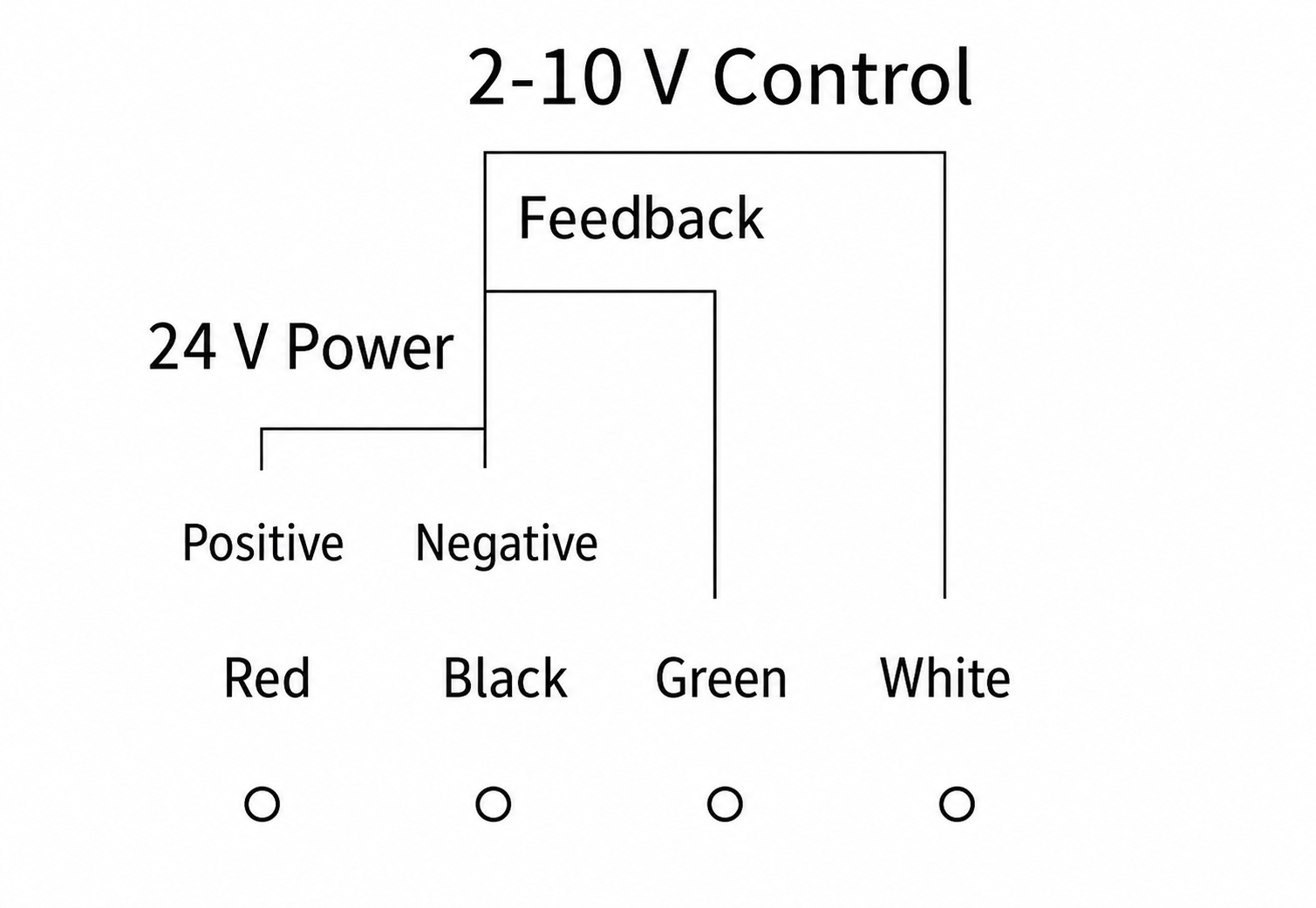
The conductor table is the working interpretation of this voltage diagram. A 4-20 mA input configuration must use its matching supplied schedule; do not transfer the white-conductor voltage assignment to a current loop without confirmation.
| Conductor | Circuit Function | Panel Check |
|---|---|---|
| Red | Positive AC/DC 24 V supply | Confirm voltage, protection and available running power |
| Black | Power and signal common / negative | Confirm the controller common-reference arrangement |
| Green | DC 2-10 V linear-position feedback | Match the receiving analog input and scaling |
| White | DC 2-10 V position command | Match the controller output and movement direction |
Position Feedback Is Not Airflow Feedback
The green conductor reports where the actuator is within its adapted stroke. It does not prove the delivered airflow, valve pressure independence, linkage force, blade sealing or fume-hood face velocity. When the control objective is airflow or pressure, a separate sensor and controller must determine the command and the controlled variable must be tested independently.
Direction and Endpoint Adaptation
Set the mechanical stroke and verify a free linkage path before running adaptation. Select the direction so increasing command produces the intended extend or retract movement, then map the two endpoints. Test minimum, midpoint and maximum demand after adaptation. Midpoint testing is important because a mechanism can reach both endpoints while still binding or distorting partway through its travel.
Linkage Design and Mechanical Fit
A fast linear actuator can only deliver controlled movement when the attachment points keep the actuator and controlled mechanism aligned. The selected holes, brackets and moving arms determine effective stroke, mechanical advantage and side load. Review the complete linkage rather than treating the actuator as a drop-in replacement for a rotary shaft drive.
Effective Stroke and Attachment Points
The actuator can be mechanically set from 10 to 100 mm. Select attachment holes that produce the required controlled-device movement without using either end as a hard stop. The effective travel at the valve or damper can differ from actuator travel when a lever or angled linkage is used, so show both dimensions on the installation drawing.
Alignment and Side Load
The linkage should move in the same line as the actuator output. Offset brackets or changing linkage angles can introduce side load, friction and a nonlinear relationship between actuator position and valve position. Keep mounting surfaces rigid, avoid twisting the actuator enclosure and verify that the moving arms clear adjacent frames, ducts and cables over the full stroke.
Force Through the Complete Travel
The 100 N rating must cover the highest push or pull load encountered anywhere in the movement. Seals, springs, cone mechanisms, pressure loading, contamination and linkage geometry can make the endpoint load different from the middle of travel. Obtain the controlled-device force requirement or measure it under the intended operating condition; do not infer suitability from duct diameter or damper area alone.
Fast Movement Changes the Mechanical Review
A 100 mm movement in approximately 3 seconds accelerates the linkage more rapidly than a standard-speed actuator. Check that brackets, pins, holes and stops can tolerate repeated movement without impact or looseness. The control sequence should also avoid unnecessary command oscillation, which can increase wear even when the nominal force remains below 100 N.
Service and Removal Clearance
Leave access to the cable, cover, direction switch, adaptation control, position indicator and linkage fasteners. The actuator may need to be removed without dismantling the complete valve or duct section. Document the required removal path on installations where multiple valves or confined ceiling spaces restrict access.
Applications and Project Fit
This fast linear damper actuator is intended for VAV airflow-control products and ventilation mechanisms that use straight-line movement. The application must provide a compatible linkage, a load within 100 N, a selected stroke within 10-100 mm and an analog control sequence that can use the 3-second response.
VAV Air Valves and Linear Damper Mechanisms
XICHENG uses the 3S100N direct-stroke configuration with applicable VAV products, including packages in which a linear actuator changes the airflow setting of a Venturi air valve. The actuator moves the selected mechanism; pressure compensation, characterised airflow and system control remain functions of the valve body, controller and sensor package. Compatibility must be confirmed from the exact linkage and supplied control arrangement.
Laboratory Supply and Exhaust Control
The rapid response can support laboratory supply, general exhaust, room tracking or fume-hood exhaust arrangements when the complete control loop requires fast valve repositioning. The 2-10 V or 4-20 mA demand may come from an airflow, pressure, room or fume-hood controller. The actuator does not establish the target airflow or safe face velocity, and its three-second movement does not by itself prove the response time of the complete ventilation system.
Other Straight-Stroke Ventilation Mechanisms
The product may be evaluated for compatible louvers, sliding dampers or custom air-control mechanisms when their force, stroke, mounting and environment are documented. A custom mechanism needs a drawing that identifies fixed and moving attachment points, load direction and clearances. Do not assume that a generic linear actuator connection will fit without a designed bracket or linkage.
Applications Requiring a Different Product
Use a rotary actuator when the damper is designed around a direct shaft connection. Do not use this product as a certified fire or smoke actuator, a spring-return fail-safe device, an outdoor or washdown actuator, an explosion-protected actuator or a hydronic valve actuator unless the exact delivered configuration carries the required evidence. No such ratings are documented for this product.
Conditions That Require Confirmation
- Peak mechanism force at normal, emergency and pressure-loaded conditions
- Required stroke, linkage ratio, alignment and endpoint clearance
- Controller output version, common reference and feedback scaling
- Power-loss and lost-command position or system response
- Environmental, chemical, enclosure and local compliance requirements
How to Select and Specify the Actuator
Selection begins with the controlled mechanism, not with the actuator model. Define the required movement and load, then confirm speed, electrical I/O and failure behavior. This sequence prevents a fast actuator from being chosen for a linkage it cannot move or control correctly.
1. Confirm Linear Motion Is Required
Identify whether the controlled device uses a sliding element, rack, lever or other push-pull mechanism. If the device is designed for direct shaft rotation, compare a rotary actuator instead. Converting rotary motion to linear motion through an unverified field linkage can change force, travel and position mapping.
2. Calculate Required Force
Obtain the maximum push and pull load across the full operating range, including pressure, seals, springs and friction. Apply the design margin required by the project and confirm the result remains within 100 N. State the load condition so the force value can be reviewed rather than entered as an unexplained number.
3. Set the Effective Stroke
Define the exact movement needed at the controlled device and map it to an actuator setting between 10 and 100 mm. Include the selected attachment holes and linkage ratio. A shorter adapted stroke must still preserve the required minimum, normal and maximum valve positions without reaching a damaging mechanical stop.
4. Check Response and Power
The product completes 100 mm in approximately 3 seconds and draws 55 W while running. Confirm that the ventilation sequence benefits from this speed and that the transformer and conductors support all actuators that may move together. Holding demand is much lower, so panel sizing based only on the 0.5 W holding value would be incorrect.
5. Match Command and Feedback
Specify either the 2-10 V or 4-20 mA input version and confirm the controller output. The 2-10 V position feedback must be assigned to a compatible receiving input if it is used. Airflow, pressure or face velocity requires its own sensor and should not be inferred from actuator position.
6. Define Failure and Override Behavior
State what the ventilation system must do after loss of power, loss of command or invalid feedback. This actuator has no documented automatic spring-return or network fallback. The required safe state must therefore be provided by the selected system architecture or another actuator family when necessary.
Information Needed to Configure the Product
- Controlled valve or damper, application and operating modes
- Maximum push/pull force and the condition used to determine it
- Required stroke, linkage ratio, mounting holes and full assembly drawing
- Required movement time and frequency of operation
- AC/DC 24 V source, transformer capacity and cable requirements
- 2-10 V or 4-20 mA command and 2-10 V feedback assignment
- Normal movement direction, power-loss and lost-signal sequence
- Quantity, destination and required submittal or acceptance documents
Installation and Commissioning
Mechanical alignment should be completed before power or an analog command is applied. Commissioning then maps the selected stroke, confirms movement direction and verifies that actuator position and the controlled ventilation variable behave as intended.
Mechanical Installation
- Isolate the controlled device and move it through the intended travel to check force and binding.
- Mount the actuator on a rigid surface with both movement paths aligned.
- Select linkage holes that provide the required effective stroke without using the actuator as a hard stop.
- Check full clearance around arms, brackets, ducts, cables and adjacent equipment.
- Secure pins and fasteners while preserving free movement and service access.
Electrical Connection
Verify the selected 2-10 V or 4-20 mA input version before wiring. Check the 24 V source, simultaneous running load, conductor size and signal common. For the voltage version, connect red and black to power, white to the command and green to the feedback input as shown on the supplied diagram. Do not wire a current-input version from the voltage example.
Stroke Adaptation and Position Test
Set the mechanical travel, select the required direction and run endpoint adaptation. Apply minimum, midpoint and maximum commands while observing the complete linkage. Confirm that the output does not bind, impact an end stop or exceed the controlled-device travel, and verify that the 2-10 V feedback follows the adapted position in the intended direction.
System Functional Test
For a VAV application, test the complete loop with the airflow or pressure sensor and controller. Record command, actuator position, measured airflow or pressure and response time for representative operating changes. The complete system can respond more slowly than the actuator because sensor update, controller logic, valve mechanics, fan pressure and duct dynamics also affect the result.
Commissioning Record
Record the actuator model, force rating, selected stroke, attachment holes, movement direction, command and feedback ranges, endpoint settings, running power source and observed full-stroke movement. Also record the system result and behavior after power or command loss. These values create a practical baseline for later inspection and service.
Frequently Asked Questions
What is a linear damper actuator?
A linear damper actuator moves a connected airflow-control mechanism in a straight line. It is used when a valve, sliding damper, louver or linkage needs push-pull travel instead of direct shaft rotation.
How is it different from a rotary damper actuator?
A rotary actuator is selected by torque and angle and usually clamps to a shaft. This product is selected by linear force and stroke and connects through linkage arms or mounting holes. The two architectures are not interchangeable without a designed conversion mechanism.
What force and stroke are available?
The 100 N linear actuator provides a mechanically adjustable stroke from 10 to 100 mm. Confirm the peak mechanism load and required effective movement over the complete travel before selection.
Does the three-second travel time apply at any stroke?
For the 100 mm stroke actuator configuration, the documented travel time is approximately 3 seconds. Do not assign a different speed to a shorter adapted stroke without a matching test or supplied configuration statement.
Does every unit accept both 2-10 V and 4-20 mA?
No. Voltage and current command inputs are available by configuration. Order the version that matches the controller output and follow the supplied wiring schedule for that version.
What does the 2-10 V feedback represent?
It represents the actuator’s adapted linear position. It does not measure force, airflow, differential pressure or face velocity and does not prove valve sealing or pressure-independent performance.
Is the actuator spring-return or fail-safe?
No spring-return or electronic fail-safe function is documented for this product. Define the required response after power or command loss and use a different architecture when an automatic safe position is mandatory.
Can it be used with a VAV Venturi air valve?
XICHENG uses the 3S100N direct-stroke configuration in applicable VAV product packages. Compatibility still depends on the exact valve linkage, required force, selected stroke, controller, signal and operating sequence.
How should the 24 V power source be sized?
Use the 55 W running value and the number of actuators that may move simultaneously, then check transformer capacity, conductor voltage drop and protection. Do not size the source from the 0.5 W holding value alone.
What information is required for a quotation?
Provide the controlled device, maximum push/pull force, required stroke, linkage and mounting drawing, response requirement, power source, command and feedback signals, failure sequence, controller, quantity, destination and required documents.
Contact the Xicheng Engineering Team Today.
Send the valve or damper drawing, maximum push/pull force, selected stroke, linkage and mounting-hole geometry, required response time, AC/DC 24 V source, 2-10 V or 4-20 mA command, 2-10 V feedback requirement, normal movement direction, power-loss and lost-signal sequence, controller information, quantity and destination. XICHENG will return a proposed linear damper actuator configuration, applicable mechanical and electrical data, mounting and wiring information, required confirmation items and commercial pricing.
🎯 Shenzhen Office: No. 34 Zhenxing Road (Shengtaian Heavy Industrial Park B), Loucun, Guangming New Dist, Shenzhen, Guangdong, China
☎️ WhatsApp: +86 181 2647 8161
📬 Engineering Mailbox: fanalax34@gmail.com