


Description
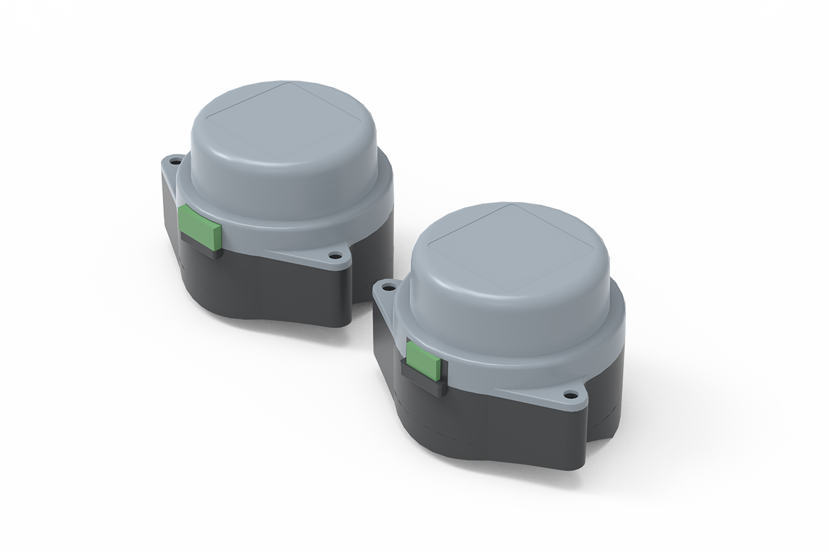
This fast on/off damper actuator moves a rotary HVAC air damper between commanded open and closed positions. It is suited to supply, exhaust, make-up-air, and equipment-interlock duties where 3- or 8-second travel is required and the documented square shaft interface is available. It is the rapid two-state option within XICHENG’s HVAC controls and damper actuators range, not a proportional airflow controller.
The confirmed family includes a 3S4N configuration with 4 Nm rated torque and 3-second travel, plus an 8S1N configuration with 1 Nm rated torque and 8-second travel. Both use AC 220 V on/off positioning, but their shaft interfaces and feedback circuits differ. The actuator is supplied separately from the damper, so the load, shaft, wiring and required end-position signal must be checked before ordering.
Product Selection Summary
Choose this on/off damper actuator when the ventilation damper only needs commanded movement between two end positions and the available shaft, torque requirement and AC 220 V control arrangement match one of the documented configurations. Use the 3S4N or 8S1N data as model-specific limits rather than treating their torque, runtime, shaft and feedback details as interchangeable.
Choose This Fast On/Off Damper actuator When
- The damper requires open/close control rather than continuous proportional positioning.
- The mechanical interface accepts an 8 x 8 mm or 10 x 10 mm square shaft with the documented engagement length.
- The control panel can provide the documented AC 220 V switching arrangement.
- Passive 0-degree and 90-degree status contacts are suitable for end-position indication.
- The required damper torque remains within the actuator’s rated output after allowing for blade friction, seals and operating pressure.
Evaluate Another Actuator Type When
- The damper must hold intermediate positions from a 0-10 V, 2-10 V or 4-20 mA command. Use a modulating damper actuator.
- The damper must move automatically to a defined safe position after power loss. Use a spring-return damper actuator.
- The installation is exposed to corrosive fumes or requires a documented protective enclosure. Use a corrosion-resistant actuator selected for the actual environment.
- The project requires a complete damper assembly rather than an actuator-only supply.
Information Required for Selection
Provide the damper type, shaft dimensions, required torque, preferred runtime, supply voltage, open/close control sequence, required position feedback, installation orientation, operating environment, quantity and destination. A shaft drawing or photograph should be included when the actuator will be fitted to an existing damper.
Key Specifications and Model Selection
The two documented configurations serve the same open/close control task but use different mechanical and electrical arrangements. Select from the actual damper torque, required travel time, shaft interface and feedback input.
Published Model Comparison
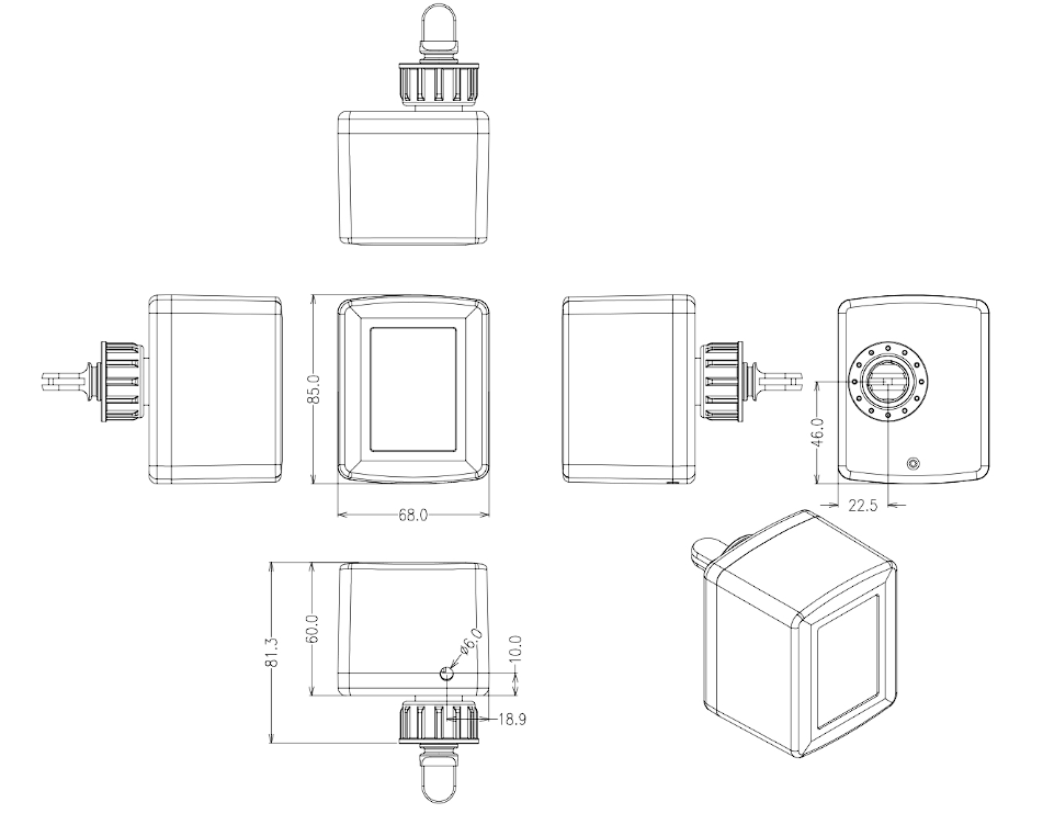
Use the drawing and comparison table together rather than selecting from torque alone. The drawing establishes the body envelope, coupling position and D10/D11 shaft interface for the 3S4N configuration; the table then compares those mechanical details with runtime, supply and position-feedback requirements. The 8S1N uses a different enclosure and square-shaft interface, so the drawing below must not be transferred to that configuration.
| Specification | 3S4N | 8S1N | Selection Note |
|---|---|---|---|
| Control type | On/off open-close | On/off open-close | Neither configuration provides proportional modulation |
| Rated torque | 4 Nm | 1 Nm | Confirm damper breakaway and running torque |
| Rated runtime | 3 seconds | 8 seconds | Match the required system sequence |
| Rated supply | AC 220 V, 50/60 Hz | AC 220 V, 50/60 Hz | Documented range for both: AC 200-240 V |
| Rated current | 31 mA | 20 mA | Use the selected model in the circuit schedule |
| Power consumption | 7 W | 4.5 W | Confirm panel capacity for the total actuator count |
| Electrical connection | 5-core lead | 6-core terminal connection | Follow the model-specific supplied diagram |
| Rotation | Maximum 90 degrees | Maximum 90 degrees | Align end positions with damper blade travel |
| Position feedback | Active 220 V feedback for 0-degree and 90-degree positions | Passive contacts for 0-degree and 90-degree positions | Feedback type must match the controller or BMS input |
| Shaft interface | D10/D11 flattened shaft interface | 8 x 8 mm or 10 x 10 mm square | 8S1N engagement length: 11 mm |
| Overall dimensions | 85 x 68 x 81 mm | 86 x 69.8 x 46.6 mm | Allow wiring and removal clearance |
| Manual operation | None | None | Plan commissioning access and isolation |
| Sound level | 40 dB or less | 35 dB or less | Published sheets do not state test conditions |
| Weight | Approximately 290 g | Approximately 167 g | Actuator only |
Before requesting a quotation, confirm the required torque and runtime, shaft form, available mounting clearance, supply voltage and receiving feedback input. For 3S4N, allow for the 85 x 68 x 81.3 mm illustrated envelope, verify that the shaft fits the D10/D11 coupling, confirm sufficient shaft projection for full engagement, and preserve access for wiring and removal. Record which blade position corresponds to 0 degrees and 90 degrees. For 8S1N, use its 86 x 69.8 x 46.6 mm enclosure and 8 x 8 mm or 10 x 10 mm square-shaft interface rather than transferring dimensions from the drawing above.
Fast On/Off Damper actuator Overview
What the Actuator Controls
An on/off damper actuator converts an electrical open or close command into rotary movement at the damper shaft. The actuator is appropriate when the sequence requires two defined end positions rather than continuous control of blade angle. Typical commands may come from a switch, relay output, equipment interlock or control panel, provided the supply and switching arrangement match the actuator wiring.
Both documented configurations move through a maximum 90-degree rotation and provide signals for the two end positions. The 3S4N uses active 220 V feedback, whereas the 8S1N provides passive contacts. These signals indicate actuator position; they do not measure damper airflow, duct pressure or blade sealing performance.
Direct-Coupled Mechanical Arrangement
A direct-coupled actuator is mounted at the damper shaft instead of driving the blade through a separate external linkage. This arrangement reduces linkage parts, but it makes shaft geometry and alignment decisive. The 3S4N drawing uses a D10/D11 flattened shaft interface; the 8S1N drawing shows an 8 x 8 mm or 10 x 10 mm square interface with 11 mm engagement. The installed shaft must match the selected configuration and enter without binding or damaging the coupling.
Actuator-Only Supply Scope
This page describes the electric actuator, not a complete motorized damper. A complete assembly may also require the damper body, blade, shaft, bearings, seals, mounting plate, controller, protective enclosure, field wiring and commissioning. XICHENG can review the actuator together with a new damper or an existing shaft arrangement, but the final quotation must identify the supplied components and the installation responsibilities.
Direct-Coupled Mounting and Mechanical Fit
The actuator must be selected from the actual damper mechanism rather than from duct size alone. Damper blade area affects load, but seal friction, bearing condition, pressure difference, blade geometry and shaft alignment can produce a higher breakaway torque than a simple area estimate suggests.
Damper shaft Compatibility
The 3S4N drawing identifies a D10/D11 flattened shaft interface, while the 8S1N accepts an 8 x 8 mm or 10 x 10 mm square shaft with 11 mm engagement. Before ordering, check the shaft cross-section at the mounting point, usable protruding length, flats or shoulders, and the clearance required for the selected actuator body.
An adapter or custom bracket may be required when the existing shaft size, shape or orientation does not match the actuator. An adapter must transmit the full required torque without introducing play. It must also keep the actuator body restrained so the housing does not rotate as the output coupling moves the damper.
The 3S4N dimensional drawing shown with the model specifications should be read together with the actual damper drawing. A torque-compatible actuator can still be mechanically unsuitable when the coupling, shaft projection, mounting side or removal clearance does not match.
Close these mechanical checks before ordering:
- Confirm that the selected damper has the D10/D11 flattened shaft required by the illustrated 3S4N coupling.
- Allow space around the 85 x 68 x 81 mm actuator body for wiring, installation and future removal.
- Record the actuator mounting side and the shaft position that corresponds to the damper’s fully open and fully closed states.
- Do not transfer this drawing to 8S1N; that configuration has an 86 x 69.8 x 46.6 mm enclosure and a square-shaft interface.
Torque Selection
The documented rated torque is 4 Nm for 3S4N and 1 Nm for 8S1N. Compare the selected value with the damper manufacturer’s requirement or a verified measurement of the existing mechanism. Include the highest expected pressure condition, seal compression, contamination and cold-start or long-idle friction. Do not select an actuator solely because the shaft physically fits.
Where the damper requires more than 1 Nm, select a higher-output XICHENG actuator with matching control and mounting characteristics. Do not use two small actuators on one shaft unless the damper and control design specifically supports synchronized operation.
Rotation and End-Position Alignment
The actuator provides up to 90 degrees of travel. Confirm the damper’s fully closed and fully open shaft positions before installation, then align the actuator to the same movement range. Forcing the actuator beyond the damper’s mechanical stop can overload the coupling, shaft or gear train. The open/close command and feedback contacts must also agree with the required clockwise or counterclockwise blade sequence.
On/Off Control, Wiring and Position Feedback
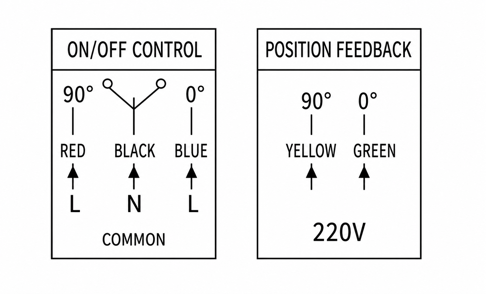
Both configurations use AC 220 V open/close control, but their position-feedback circuits are not interchangeable. The 3S4N diagram shows active 220 V feedback conductors, while the 8S1N sheet identifies passive end-position contacts. The controller input and field wiring must match the selected configuration.
3S4N Command and Feedback Circuit
Before the panel I/O schedule is finalized, separate the open/close command circuit from the end-position feedback circuit. Read the diagram from left to right: red or blue receives the selected switched-line command, black remains the common neutral, and yellow or green reports the resulting end position. The control panel must interlock the two commands and its feedback inputs must accept energized AC 220 V signals.
| Circuit Function | 3S4N | 8S1N | Connection Check |
|---|---|---|---|
| Control common | Black: neutral | Black, terminal 1: neutral | Verify the final conductor and terminal schedule |
| 90-degree command | Red: switched line | Red, terminal 2: switched line | Interlock against the opposite command |
| 0-degree command | Blue: switched line | Blue, terminal 3: switched line | Confirm the installed open/closed direction |
| 90-degree feedback | Yellow: active 220 V feedback | Yellow, terminal 4: passive contact | Match the receiving input type |
| 0-degree feedback | Green: active 220 V feedback | Green, terminal 5: passive contact | Do not treat feedback as airflow measurement |
| Feedback common | Not shown as a separate conductor | White, terminal 6: passive-contact common | Use only the selected model’s supplied diagram |
Use the diagram and conductor table as one wiring reference when assigning panel terminals. The 3S4N command conductors switch the actuator between its two end positions and its yellow/green conductors return energized 220 V position signals. Do not transfer that feedback circuit to 8S1N, which uses passive end-position contacts and a separate feedback common.
Direction and End-Position Confirmation
The upstream relay or switch must command one end position at a time; the sequence must prevent the red and blue drive conductors from being energized together. Confirm the installed direction during commissioning because mounting the actuator on the opposite side of a damper, or reversing the blade linkage, can change which shaft position represents open and closed.
For 3S4N, yellow and green are active 220 V end-position outputs. For 8S1N, the separate product sheet identifies passive contacts and a feedback common. Match the receiving controller or BMS input to the selected model. End-position feedback confirms actuator travel only; it does not prove damper sealing, unobstructed blade movement or the required airflow.
Electrical Checks Before Connection
- Verify AC 220 V, 50/60 Hz supply within the documented AC 200-240 V range.
- Confirm the actuator model and terminal/color schedule against the supplied wiring diagram.
- Use interlocked outputs so open and close commands cannot be energized together.
- Match the active or passive feedback circuit to the receiving input before connection.
- Provide circuit protection, isolation and cable routing appropriate to the installation.
Applications and Project Fit
This on/off electric damper actuator is suitable where a ventilation damper must move between two commanded positions and does not require continuous blade modulation. The compact direct-mount arrangement is most useful when the damper shaft and available installation space match the actuator without a complex external linkage.
Suitable Ventilation Applications
- Equipment exhaust or supply-air dampers that open when the connected equipment starts and close when it stops.
- HVAC supply, return or exhaust branches that require a basic isolation or enable/disable damper under a defined control sequence.
- Make-up air, general exhaust or fresh-air dampers controlled from a relay, switch or equipment interlock.
- Compact rotary dampers where a 1 Nm actuator is sufficient and the documented square shaft interface is available.
- Retrofit applications where the existing shaft, load and installation clearance can be verified before ordering.
Applications That Require a Different Product
Do not use this actuator where the damper must track a variable airflow setpoint, maintain room pressure or continuously adjust blade position. Those functions require a modulating actuator or a complete airflow-control package with the appropriate sensor and controller.
Neither documented configuration includes a mechanical spring-return function. Where power loss must drive the damper automatically to a defined safe position, select a spring-return actuator and verify the required normal and fail position. This family is also not presented as a certified fire or smoke damper actuator, so it must not be substituted into a listed life-safety assembly without the required approvals.
For chemical exhaust, review the actuator enclosure, exposed hardware, cable entry and mounting location against the actual contaminants and condensation risk. A standard on/off actuator should not be described as corrosion-resistant unless the selected product documentation confirms that construction and its exposure limits.
How to Select the Correct On/Off Damper actuator
Correct actuator selection requires one mechanical check, one electrical check and one sequence check. The actuator must fit the shaft and overcome the real damper load, the control panel must match the supply and wiring, and the commanded end positions must agree with the required operating and power-loss sequence.
1. Confirm the Damper Mechanism
Record the damper type, blade arrangement, shaft shape, shaft dimensions, usable shaft length and mounting surface. Identify the fully open and fully closed positions and note whether the actuator will be mounted on the left or right side. For an existing damper, include photographs and a dimensioned shaft sketch.
2. Establish Required Torque
Use the damper manufacturer’s actuator-sizing value where available. If it is not available, determine breakaway and running torque under the highest expected pressure and seal load. The documented choices are 4 Nm for 3S4N and 1 Nm for 8S1N; neither should be selected when the verified requirement exceeds its rating or leaves an inadequate operating margin.
3. Match Runtime to the Control Sequence
The confirmed model has an 8-second rated runtime. Check whether the equipment sequence requires the damper to prove open before a fan or process starts, and whether the available delay is long enough for full movement plus status confirmation. Runtime alone does not establish airflow response because the connected damper, duct and fan have their own dynamic behavior.
4. Confirm Supply and Control Outputs
Verify AC 220 V power, the available relay or switch outputs, conductor arrangement and feedback input type. If the panel provides a proportional analog output instead of switched open/close commands, select a modulating actuator rather than adding an improvised interface.
5. Define the Power-Loss Position
An ordinary on/off actuator stops when it loses power; it does not automatically provide a safe return position. State whether the damper may remain at its last position or whether a mechanical spring-return function is required. This decision is particularly important for exhaust isolation, make-up air and safety-related sequences.
6. Review the Installation Environment
Provide the ambient temperature, humidity, condensation risk, chemical exposure, washdown conditions and whether the actuator is installed inside or outside the contaminated air stream. If the environment requires a protective enclosure or corrosion-resistant construction, specify that requirement explicitly instead of assuming it from the actuator color or housing appearance.
Quotation Input Checklist
- Damper type, blade size and service.
- Shaft cross-section, dimensions and usable engagement length.
- Required torque and required open/close time.
- Supply voltage and available control outputs.
- Required end-position feedback and upstream input type.
- Normal position and acceptable position after power loss.
- Ambient and chemical exposure conditions.
- Quantity, destination and any required mounting parts.
Installation and Commissioning
Installation should confirm mechanical freedom before electrical operation. The actuator must not be used to force a seized, misaligned or incorrectly stopped damper through its travel.
Pre-installation Checks
- Isolate electrical power and verify the actuator model against the approved schedule.
- Move the damper through its intended range and correct binding, damaged bearings or obstructed blades.
- Confirm shaft size, engagement length, actuator orientation and available wiring clearance.
- Align the damper and actuator to corresponding end positions before tightening the coupling and restraint.
- Check that the actuator housing and cable are protected from the air-stream and environmental conditions stated in the project.
Electrical and Functional Test
A qualified technician should connect the actuator according to the model-specific diagram. Command each direction separately, verify complete travel, and confirm that the 0-degree and 90-degree feedback contacts change at the expected positions. Check that the controller does not energize both movement commands at once.
System Acceptance
After mechanical movement is confirmed, test the complete equipment sequence. Verify the damper’s physical open and closed positions, interlocks, alarms and the behavior after control power is removed. Where airflow or isolation performance matters, confirm it separately; actuator position feedback alone is not proof of airflow or leakage performance.
Frequently Asked Questions
Is this a complete motorized damper?
No. The product described here is an electric actuator. A complete motorized damper also includes the damper body, blade, shaft, bearings, seals, mounting parts and, where required, a controller or sensor package. The quotation should identify whether XICHENG is supplying the actuator only or an assembled damper.
Is an on/off actuator the same as a modulating actuator?
No. An on/off actuator moves to commanded end positions. A modulating actuator accepts a proportional command and can hold intermediate positions. Select a modulating product when the damper must regulate airflow or pressure continuously rather than simply open or close.
Does this on/off damper actuator return to a safe position when power is lost?
The documented 3S4N and 8S1N configurations do not specify a mechanical spring-return function. Do not assume fail-safe return. If the damper must move automatically to a defined position without power, specify a spring-return damper actuator and the required return direction.
What does the actuator’s position feedback confirm?
The passive contacts indicate the actuator’s 0-degree or 90-degree end position. They do not confirm airflow, duct pressure, damper leakage or successful process ventilation. Use the appropriate airflow, pressure or equipment proof signal when the control sequence requires those conditions.
Can the actuator be fitted to an existing damper?
It can be considered when the existing damper shaft, required torque, travel range and mounting clearance match one of the documented configurations. The 3S4N and 8S1N use different shaft interfaces, so send a shaft drawing and photographs before ordering a retrofit.
What information is required to select the correct model?
Provide the damper type, shaft dimensions, required torque, desired runtime, supply voltage, control logic, position-feedback requirement, power-loss position, environment, quantity and destination. Include the damper drawing or an existing-shaft sketch where available.
Contact the Xicheng Engineering Team Today.
Send the damper type, shaft dimensions, required torque, open/close time, supply voltage, control and feedback arrangement, normal and power-loss positions, operating environment, drawings, quantity, and destination. XICHENG will review the actuator fit and provide the applicable model, mounting and wiring information, included components, documentation, and commercial pricing.
🎯 Shenzhen Office: No. 34 Zhenxing Road (Shengtaian Heavy Industrial Park B), Loucun, Guangming New District, Shenzhen, Guangdong, China
☎️ WhatsApp: +86 181 2647 8161
📬 Engineering Mailbox: fanalax34@gmail.com