


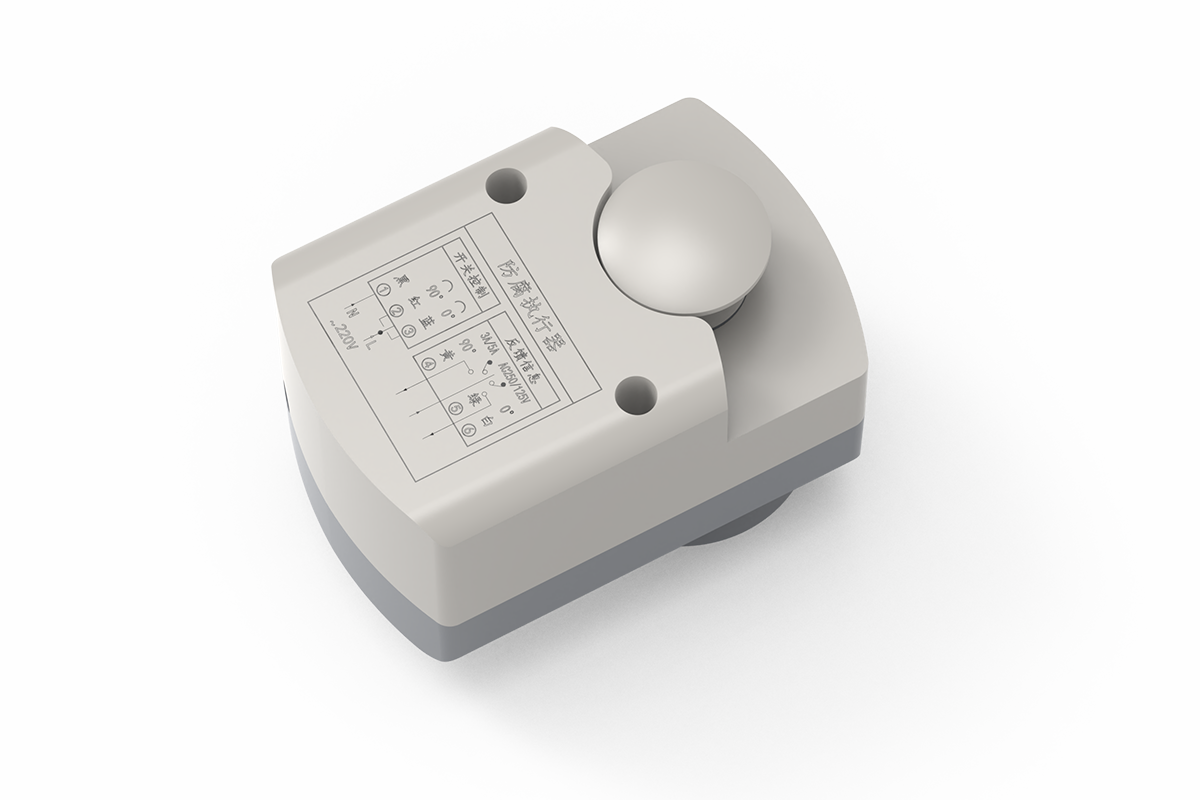
Description
This corrosion-resistant on/off damper actuator provides powered open/close movement for laboratory exhaust, chemical ventilation plant areas, and other indoor locations where corrosive exposure requires additional review. It is the environmental-duty option within XICHENG’s laboratory airflow controls and actuators range. The designation applies to the selected actuator configuration and installation arrangement; it does not establish chemical resistance for the complete damper assembly.
Corrosion-Resistant Damper actuator Overview
What the Actuator Controls
The actuator rotates a compatible ventilation damper shaft between two defined end positions. Switched power commands the open or closed state, while voltage-free contacts can report the configured end positions to a relay panel, PLC or building management system. This is two-state control rather than proportional positioning.
Why Environmental Duty Matters
Torque and runtime determine whether the actuator can move the damper, but the mounting atmosphere determines whether the enclosure, cable entry, fasteners and exposed hardware are suitable for the location. A unit mounted outside a sealed exhaust duct faces a different duty from one exposed to condensate, washdown or leaking process vapor.
Actuator-Only Supply Boundary
The product is an actuator, not a complete corrosion-resistant damper or certified isolation assembly. Damper body, blade, shaft, seals, bearings, mounting cover, control panel and field wiring remain separate unless included in the quotation. End-position contacts do not measure airflow or prove shutoff leakage.
Product Selection Summary
Choose This Actuator When
Select this corrosion-resistant damper actuator when the damper needs powered open/close movement and the installation environment requires more careful material and enclosure review than standard indoor service. Available configurations provide 2, 5, 8 or 10 Nm torque with 4, 6, 30 or 17 second travel, allowing the actuator to be matched to both mechanical load and sequence timing.
The family is relevant to laboratory ventilation plant areas, technical exhaust branches, humid service spaces and equipment zones near potentially corrosive processes. The actuator should normally remain outside the process air stream unless the selected arrangement is specifically confirmed for direct exposure.
Evaluate Another Actuator Type When
Use the on/off direct-coupled damper actuator for compact, very fast standard indoor operation. Evaluate the spring-return damper actuator when loss of power must move the damper to a defined position, or the modulating damper actuator when the blade must hold intermediate positions.
Information Required for Selection
Provide damper type, shaft size, required torque, runtime, voltage, control sequence, feedback points and mounting orientation. Also state indoor or outdoor location, humidity, condensation, cleaning method and any salt, acid or alkali vapor, including chemical name, concentration and temperature where applicable.
Key Specifications and Configuration Selection
4S2N Dimensions and Family Comparison
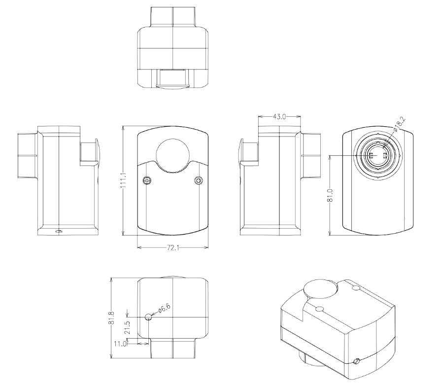
The drawing below applies specifically to the compact 4S2N configuration. Confirm its 111.1 x 72.1 x 84.4 mm envelope, shaft centerline and access clearance before comparing it with the separate housing used by the 5, 8 and 10 Nm configurations.
| Configuration | Torque | Runtime | Supply | End-Position Feedback | Envelope |
|---|---|---|---|---|---|
| 4S2N | 2 Nm | 4 s | AC 220 V | Voltage-free contacts shown | 111.1 x 72.1 x 84.4 mm |
| 6S5N | 5 Nm | 6 s | AC 220 V | Voltage-free contacts | 123.8 x 72 x 61.5 mm |
| 30S8N | 8 Nm | 30 s | AC 24 V or AC 220 V | Voltage-free contacts | 123.8 x 72 x 61.5 mm |
| 17S10N | 10 Nm | 17 s | AC 220 V | Voltage-free contacts | 123.8 x 72 x 61.5 mm |
The 4S2N configuration requires at least 75 mm shaft engagement. The 6S5N, 30S8N and 17S10N configurations use the 123.8 x 72 x 61.5 mm housing and require at least 50 mm engagement. Keep each housing, torque, runtime and voltage combination tied to its own configuration.
Shared Operating Data
| Field | Available Family Data | Selection Check |
|---|---|---|
| Control mode | Powered on/off rotation through switch control | Confirm the relay sequence and normal position |
| Rotation | Maximum 90 degrees; switch-adjustable travel limit | Set limits to the installed damper stroke |
| Position indication | Local scale and voltage-free end-position contacts | Assign open and closed proof points |
| Power | 7 W | Size protection and switching components for the selected voltage |
| Lead | Six-core, 0.3 mm2, approximately 150 mm | Provide a suitable junction and conductor identification |
| Operating environment | -20 to +50 degrees C; up to 95% RH, noncondensing | Review any condensation or liquid-water exposure separately |
| Storage | -30 to +60 degrees C | Maintain suitable transport and storage conditions |
This family is not specified as spring return, continuously modulating, fire/smoke certified or explosion-proof. Select those functions separately when the project requires them.
Corrosion-Resistance Scope
What Corrosion-Resistant Means for Selection
This actuator family is intended for ventilation duties where corrosion exposure is an explicit selection factor. Suitability still depends on the complete exposed assembly, including enclosure, shaft interface, fasteners, cable entry, seals, mounting hardware and any protective cover. The mounting location relative to the process air stream is equally important.
Environmental Data Needed
| Exposure | Why It Matters | Information to Provide |
|---|---|---|
| Humidity or condensation | The stated humidity limit is noncondensing | Maximum RH, dew-point risk, drainage and orientation |
| Chemical vapor | Compatibility changes with chemistry and temperature | Chemical, normal/upset concentration, gas temperature and exposure duration |
| Outdoor or washdown location | Rain and water jets require a defined enclosure rating | Rain, UV, cleaning method and required IP/NEMA class |
| Salt or marine atmosphere | Fasteners and cable entries may limit service life | Salt exposure and required material standard |
| Process-air contact | Direct exposure is more severe than external ambient air | Actuator position, shaft seal and duct pressure |
Claims That Need Configuration-Specific Confirmation
Specify required enclosure material, gasket, coating, IP/NEMA class and chemical compatibility in the inquiry when they are contract requirements. Corrosion-resistant does not automatically mean resistance to every acid or alkali, outdoor weatherproofing, washdown suitability or explosion protection.
Direct-Coupled Mounting and Mechanical Fit
Match Torque to the Installed Damper
Required torque depends on blade area, seal compression, bearing condition, differential pressure, linkage geometry, contamination and starting friction. Use measured or calculated breakaway torque and apply the project margin. Do not select 2 Nm simply because a damper is compact or 10 Nm simply because it is the largest available option.
Shaft Engagement and Housing Fit
All four configurations use a D16 shaft interface, but minimum engagement differs. The compact 4S2N requires at least 75 mm; the 5, 8 and 10 Nm housing requires at least 50 mm. Confirm shaft profile, clamp range, anti-rotation restraint and usable insertion length before release.
Installation Envelope
The 4S2N body measures 111.1 x 72.1 x 84.4 mm and weighs 355.5 g. The 6S5N, 30S8N and 17S10N body measures 123.8 x 72 x 61.5 mm and weighs 445 g. Show orientation, shaft insertion, cable exit, junction location and removal clearance on the installation drawing.
On/Off Control, Wiring and Position Feedback
Powered End-Position Logic
Switched power moves the actuator to its configured 0-degree or 90-degree position. This architecture suits equipment interlocks, branch enable/disable and scheduled ventilation changeover. It does not accept a continuous 0-10 V demand for intermediate positioning.
Wiring and Feedback Reference
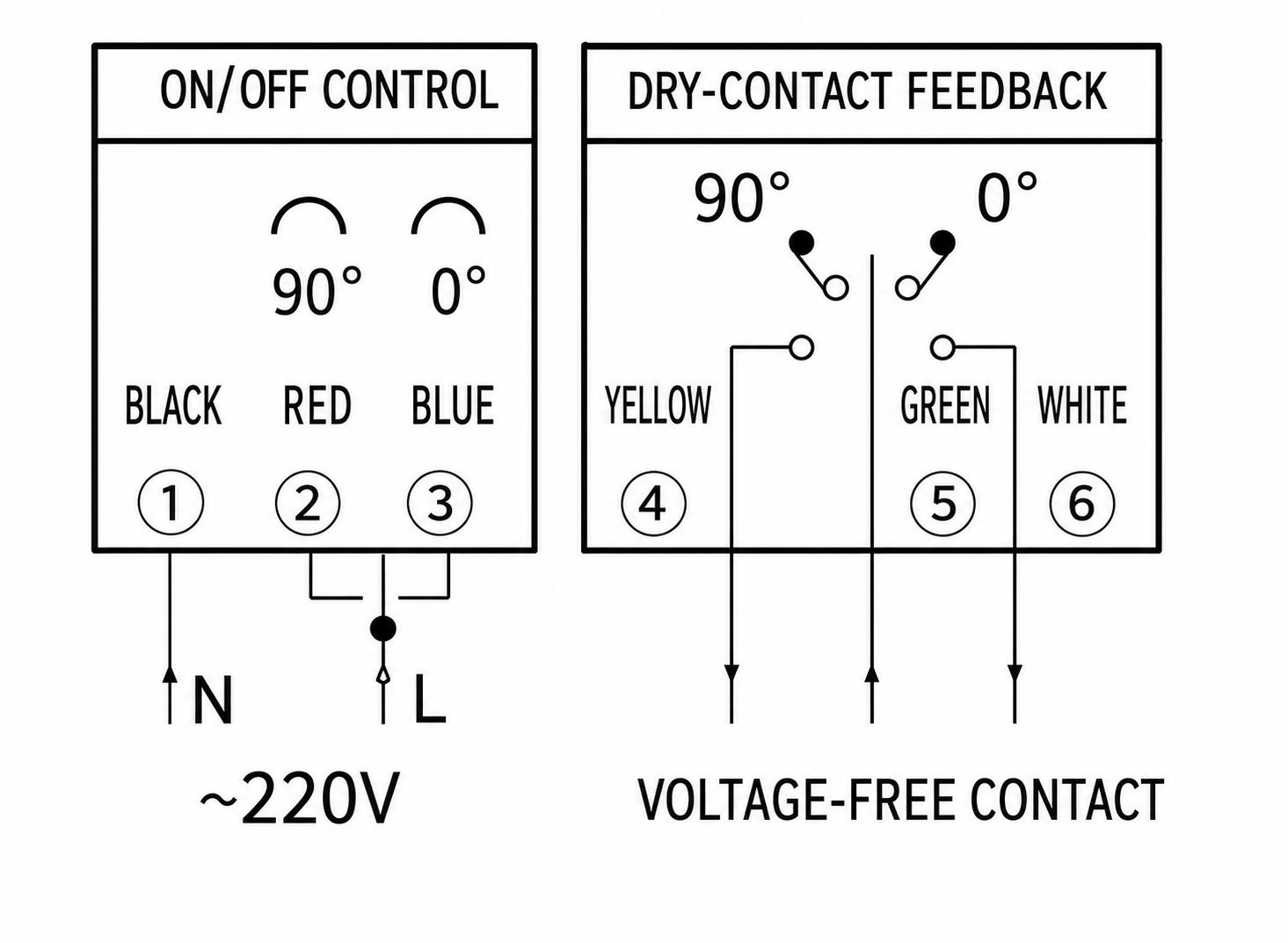
The wiring figure shows the AC 220 V open/close arrangement and voltage-free end-position contacts used by the six-core connection. Obtain the correct diagram for the selected voltage before panel fabrication, especially for the AC 24 V 30S8N option.
| Circuit Function | Purpose | Coordination Check |
|---|---|---|
| Open command | Drives the actuator toward the configured open end | Verify supply voltage and relay logic |
| Close command | Drives the actuator toward the configured closed end | Prevent conflicting commands |
| 0-degree contact | Reports one configured end position | Map the contact to the actual blade state |
| 90-degree contact | Reports the opposite configured end position | Confirm the switch point during commissioning |
| Common feedback contact | Completes the receiving dry-contact circuit | Provide the panel or BMS sensing supply |
What End-Position Feedback Proves
The contacts show that the actuator reached its switching point. They do not measure airflow, verify leakage class or prove process isolation. Acceptance testing should compare command, actuator scale, shaft movement, actual blade position and remote feedback.
Applications and Project Fit
Laboratory and Technical Ventilation
This corrosion-resistant on/off actuator can serve laboratory mechanical spaces, technical exhaust branches, humid service areas and ventilation equipment near processes that may release corrosive vapor. It can open a branch with equipment enable, close it when the branch is out of service, or provide scheduled two-position operation.
Keep the Complete Damper assembly in the Review
Actuator selection does not establish the damper body’s leakage, pressure rating or chemical compatibility. Confirm blade, shaft, seals, bearings, frame or duct body, fasteners and mounting hardware as one assembly. A suitable actuator attached to an incompatible damper does not create a corrosion-resistant ventilation package.
Applications That Require Another Architecture
Choose spring return where loss of power must move the damper to a defined position. Choose proportional control where airflow, pressure or temperature requires intermediate blade positions. This family is not specified as a fire/smoke actuator, certified isolation device, explosion-proof product or liquid-process valve actuator.
How to Select and Specify a Corrosion-Resistant Damper actuator
1. Establish Mechanical Load
Calculate or measure damper breakaway torque, apply the project margin and select among 2, 5, 8 and 10 Nm. Confirm D16 shaft fit and the minimum engagement for the selected housing.
2. Match Runtime to the Sequence
Compare the 4, 6, 30 and 17 second options with the equipment interlock and alarm timing. A faster actuator is not suitable if it lacks the required torque.
3. Confirm Voltage and Feedback
Specify AC 220 V or the available AC 24 V 30S8N configuration, relay logic and required open/closed feedback points. Use the wiring diagram supplied for that voltage.
4. Define Environmental Duty
State temperature, humidity, condensation, water exposure, cleaning method, chemical vapor and actuator location relative to the air stream. Add any required enclosure material, coating or IP/NEMA class to the inquiry.
5. Complete the Quotation Input
For each damper tag, provide application, torque, runtime, shaft dimensions, voltage, command and feedback sequence, mounting orientation, environmental exposure, quantity and destination. Include the damper drawing, control schematic and BMS point list where available.
Installation and Commissioning
Mechanical Installation
Verify free blade travel before fitting the actuator. Align the D16 shaft and restraint without side load, maintain the minimum engagement for the selected configuration and leave access to travel adjustment, indication and electrical termination. Route the cable so condensate cannot run into the enclosure or junction.
Electrical Coordination
Check nameplate voltage before energization. Use appropriately rated switching contacts, circuit protection and a junction method compatible with the installation environment. Keep powered commands and dry-contact feedback clearly identified so open, closed and fault states are not reversed.
Commissioning Sequence
- Record configuration, voltage, torque, runtime and damper tag.
- Check blade movement, shaft engagement, clamp security and restraint.
- Command both end positions and verify the required blade travel.
- Measure open and close times.
- Verify local indication and both feedback states at the receiving controller.
- Run the complete equipment interlock and alarm sequence.
- Inspect cable entry and mounting location for condensation or process leakage.
Maintenance and Troubleshooting
Routine Inspection
Inspect enclosure condition, cable entry, junction, mounting restraint, shaft clamp, visible corrosion, condensation and abnormal noise. Cycle the damper and compare actual travel with the local scale and remote contacts. Increase inspection frequency where humidity, chemical exposure or cycling duty is severe.
Troubleshooting Guide
| Symptom | Checks | Corrective Direction |
|---|---|---|
| No travel | Supply, switching relay, conductors and blade binding | Restore the command and free the damper |
| Incomplete travel | Limit setting, shaft slip, engagement and obstruction | Correct the interface and reset travel |
| Feedback does not change | Receiving circuit, common contact and switch point | Correct wiring or adjust the end switch |
| Travel is too slow | Configuration, voltage, load and contamination | Remove resistance or reassess selection |
| Corrosion or moisture appears | Condensation, washdown, process leakage and cable entry | Stop the exposure source and revalidate protection |
Related Damper actuator Options
Compare the on/off direct-coupled damper actuator for compact standard-duty operation, the two-position damper actuator for higher torque, the spring-return damper actuator for automatic de-energized movement and the modulating damper actuator for proportional control.
Frequently Asked Questions
Is this actuator resistant to every acid and alkali vapor?
No universal chemical compatibility is published for the complete family. Provide the chemical, concentration, temperature, exposure duration and mounting location so the enclosure and exposed components can be reviewed for the project.
Does corrosion-resistant mean waterproof or suitable for outdoor installation?
No. Corrosion resistance, rain protection, washdown protection and outdoor UV exposure are separate requirements. A documented enclosure rating and installation arrangement are required where water or weather exposure is expected.
Which configuration is the fastest?
The 4S2N configuration has a published 4-second runtime at 2 Nm. The 6S5N follows at 6 seconds and 5 Nm. Select runtime together with torque; the fastest configuration is not suitable if it cannot move the installed damper with the required margin.
Which option provides the highest torque?
The 17S10N configuration provides the highest published torque in this family at 10 Nm, with a 17-second runtime. The 30S8N provides 8 Nm at 30 seconds, while the smaller options provide 2 Nm and 5 Nm.
Can the actuator report damper position to a BMS?
Yes. The published wiring provides voltage-free contacts for the 0-degree and 90-degree end positions. The BMS or panel must supply the receiving circuit and map the contacts correctly.
Does end-position feedback prove airflow or tight shutoff?
No. It proves the actuator reached its configured switch point. Airflow, leakage and isolation depend on the complete damper assembly and require separate testing or documentation.
Is 24 V available?
The 30S8N product summary publishes AC 24 V and AC 220 V options. Its detailed block shows AC 220 V wiring, so the ordered voltage and corresponding wiring must be confirmed in the approved schedule.
Can this product fail closed when power is removed?
These are powered on/off configurations and no spring-return function is published. Evaluate a spring-return actuator when power loss must produce a defined fail position.
Can it be used for proportional airflow control?
No continuous proportional input is published for this family. Use a modulating damper actuator or a complete airflow-control package when intermediate positioning is required.
What information is needed to select the model?
Provide torque or damper details, required runtime, shaft size and engagement, voltage, control and feedback logic, mounting space, environmental exposure, quantity and destination.
Contact the Xicheng Engineering Team Today
Send the damper drawing, required torque and runtime, shaft dimensions, supply voltage, control sequence, installation location and environmental exposure. The engineering team will return a recommended configuration, the environmental details that need project confirmation and pricing within 24 hours.
Shenzhen Office: No. 34 Zhenxing Road (Shengtaian Heavy Industrial Park B), Loucun, Guangming New Dist, Shenzhen, Guangdong, China
WhatsApp: +86 181 2647 8161
Engineering Mailbox: fanalax34@gmail.com