


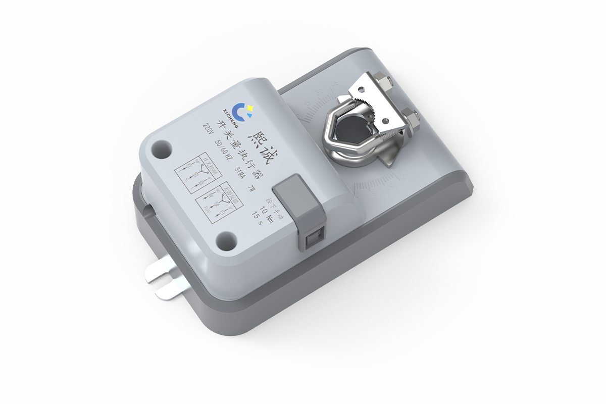
Description
- Five torque/runtime combinations from 10 Nm at 15 seconds to 35 Nm at 120 seconds
- Maximum 90-degree rotary travel with switch adjustment and visible position indication
- AC 24 V, DC 24 V and AC 220 V configurations for different panel designs
- Six-core lead, manual-release button and dry-contact end-position feedback
This two-position damper actuator moves an HVAC air damper between defined 0-degree and 90-degree positions instead of proportionally controlling intermediate blade angles. Five configurations cover 10-35 Nm torque, 15-120 second travel, and 24 V or 220 V power. Within XICHENG’s HVAC controls and damper actuators range, it is the standard two-state family for duct, equipment, and air-handling duties.
Product Selection Summary
This family belongs on the shortlist when a ventilation damper must travel fully open or fully closed under a powered command and the panel needs independent confirmation of the two actuator end positions. The configuration table should be reviewed before the detailed mounting and wiring sections because torque, runtime, voltage and shaft size are linked choices.
Choose This Product Family When
- The control sequence requires two commanded positions rather than continuous 0-10 V or 4-20 mA modulation.
- The damper’s verified operating torque falls within a suitable 10, 16, 20 or 35 Nm configuration.
- A 15, 50, 60 or 120 second travel time is compatible with the equipment and ventilation sequence.
- The control panel can provide the selected AC 24 V, DC 24 V or AC 220 V supply and interlocked direction commands.
- Dry-contact indication of the 0-degree and 90-degree actuator positions can be accepted by the controller or BMS input.
Key Configuration Range
The 10-20 Nm configurations share the 134.8 x 79.1 x 66.8 mm housing and D16 shaft interface. The 35 Nm configuration uses a 140.4 x 79 x 66.3 mm body and D20 interface. Do not select from torque alone: the selected runtime, voltage, enclosure dimensions and shaft engagement must all match the same configuration.
Use Another Actuator Family When
Select a compact on/off direct-coupled damper actuator when the 3S4N or 8S1N fast compact arrangement matches the damper. Use a planned spring-return damper actuator when loss of power must mechanically move the damper to a defined safety position. Use a planned modulating damper actuator when the required position varies continuously with an analog command. A corrosion-resistant actuator requires a separate materials and environmental review.
Information Needed for a Project-Ready Quotation
Provide the damper type, required operating and breakaway torque, desired runtime, supply voltage, shaft diameter and usable length, mounting orientation, open/closed rotation relationship, feedback-input type, ambient conditions, quantity and destination. Include the damper drawing and panel schematic when available. The quotation should return one matched configuration, its mechanical interface, wiring assignment, included scope and any unresolved project conditions.
Two-Position Damper actuator Specifications
The five configurations cover distinct torque, travel-time and supply combinations. Keep each row intact during selection; values from different rows are not interchangeable options on one fixed actuator.
Configuration Comparison
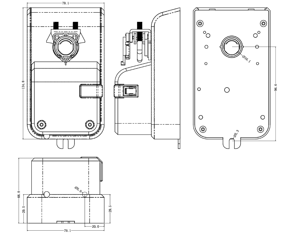
The drawing below applies to the shared 10, 16 and 20 Nm housing. Read it before the table to confirm the 134.8 x 79.1 x 66.8 mm envelope, D16 shaft interface and required mounting clearance. It does not represent the separate 35 Nm body.
| Configuration | Torque | Runtime | Supply | Dimensions | Shaft | Weight |
|---|---|---|---|---|---|---|
| 15S10N | 10 Nm | 15 s | AC 24 V or AC 220 V, 50/60 Hz | 134.8 x 79.1 x 66.8 mm | D16; engagement >=60 mm | 740 g |
| 50S20N | 20 Nm | 50 s | AC 24 V or AC 220 V, 50/60 Hz | 134.8 x 79.1 x 66.8 mm | D16; engagement >=60 mm | 740 g |
| 60S16N | 16 Nm | 60 s | AC 24 V or AC 220 V, 50/60 Hz | 134.8 x 79.1 x 66.8 mm | D16; engagement >=60 mm | 740 g |
| 50S16N | 16 Nm | 50 s | DC 24 V | 134.8 x 79.1 x 66.8 mm | D16; engagement >=60 mm | 740 g |
| 120S35N | 35 Nm | 120 s | AC 24 V or AC 220 V, 50/60 Hz | 140.4 x 79 x 66.3 mm | D20; engagement >=50 mm | 782 g |
For the illustrated housing, also preserve access to the lead exit, clamp and future removal path, and record which shaft angle represents the fully open and fully closed blade positions. For the 35 Nm configuration, use its separate 140.4 x 79 x 66.3 mm envelope, D20 interface and at least 50 mm shaft engagement.
Shared Control and Operating Data
| Field | Product Family Data | Project Check |
|---|---|---|
| Control | Powered open/close positioning | Interlock opposite direction commands |
| Rotation | Maximum 90 degrees; switch adjustable | Match damper blade travel and mounting side |
| Feedback | Dry contacts at 0 and 90 degrees | Match contact common and receiving input |
| Manual operation | Push-button gear release for manual shaft rotation | Isolate power before manual adjustment |
| Power consumption | 7 W | Size circuit for selected voltage and actuator count |
| Lead | Six-core, 0.3 mm2, 150 mm | Provide junction and extension method as required |
| Operating temperature | -20 to +50 degrees C | Confirm enclosure and condensation conditions |
| Storage temperature | -30 to +60 degrees C | Protect before installation |
| Humidity | Maximum 95% RH, non-condensing | Avoid condensation at the actuator and terminals |
| Acoustic data | 15S10N/50S20N/60S16N: <=40 dB; 50S16N/120S35N: <=35 dB | Test conditions are not stated; confirm if acoustics are critical |
Product Overview and Operating Scope
What Two-Position Operation Means
The electric damper actuator receives one command for travel toward the 90-degree end and another for travel toward the 0-degree end. It is intended for operating sequences where the damper must occupy one of two defined positions. It does not accept a proportional demand that represents every intermediate blade angle.
The 0-degree and 90-degree labels describe actuator shaft position. Whether those positions mean damper open or damper closed depends on the mounting side, shaft orientation and damper linkage. That relationship must be defined on the project drawing and confirmed during commissioning.
What the Actuator Supplies and What Remains External
The actuator supplies rotary movement, adjustable travel limits, manual gear release, position indication and dry-contact end-position signals. The damper body, shaft, bracket or adapter, power protection, interposing relays, controller, BMS logic and field junctions remain separate unless specifically included in the quotation.
Dry-contact feedback reports that the actuator reached its switching point. It does not measure airflow, differential pressure, blade leakage or process containment. Projects that require proof of airflow need a separate sensor and acceptance method.
Power-Loss and Safety-Function Boundary
This product family is selected for powered travel in both directions. It is not the mechanical spring-return family. If the risk assessment requires the damper to move automatically to a defined position when power is lost, select a spring-return configuration and define the normal and de-energized positions explicitly.
Do not treat a general two-position actuator as a certified fire or smoke damper actuator. Fire/smoke service requires the actuator, damper assembly, temperature devices, listing and installation method specified for that duty.
Mechanical Fit, Shaft and Torque Selection
Select Torque from the Damper Load
Choose 10, 16, 20 or 35 Nm from the damper manufacturer’s required torque or a verified measurement of the installed mechanism. Include breakaway torque, running torque, seal compression, bearing condition, blade pressure load, contamination and the highest expected operating pressure. Duct diameter or blade area alone is not a reliable actuator-sizing method.
Use the next suitable configuration with an engineering margin defined for the project rather than selecting exactly at the estimated peak load. An oversized actuator can also damage a light shaft or stop if the mechanical assembly is not designed for the applied output, so the damper’s allowable shaft and linkage load must be checked.
Housing and Shaft Fit
The dimensional drawing and configuration table in Key Specifications establish the applicable housing, shaft and engagement requirements before detailed mounting work begins. Review those values with the damper drawing before manufacturing the mounting plate. Confirm shaft projection, clamp access, cable exit, mounting side, anti-rotation restraint and the removal path on the coordinated assembly rather than relying on actuator dimensions alone.
Manual Release and Rotation Setup
The manual-release button disengages the gear train so the shaft can be rotated by hand during installation and alignment. Isolate the actuator supply before using the release, support the damper so it cannot move unexpectedly, and do not use the mechanism to force a seized blade or overcome a hard mechanical stop.
After the actuator and damper are aligned, set the travel switches within the required maximum 90-degree range. The actuator stop and damper stop must agree without binding. Re-engage the gear fully before powered testing.
Open/Close Control and Dry-Contact Feedback
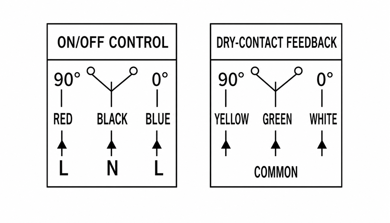
The six-core arrangement separates powered direction commands from passive end-position indication. The control panel must switch only one travel direction at a time and must read the feedback conductors as dry contacts rather than applying them as powered outputs.
Command and Feedback Wiring
The left side of the figure shows red and blue as the two direction conductors with black as common. The right side shows yellow and white as the 90-degree and 0-degree feedback contacts with green as their common. Verify the final color and terminal schedule against the supplied actuator before energizing the circuit.
| Conductor | Function | Panel Check |
|---|---|---|
| Red | Command toward 90 degrees | Use selected supply and interlock against blue |
| Black | Command common | Connect to the common shown on the supplied diagram |
| Blue | Command toward 0 degrees | Use selected supply and interlock against red |
| Yellow | 90-degree dry-contact feedback | Connect to compatible status input |
| Green | Feedback common | Keep separate from the powered command common unless the approved schematic says otherwise |
| White | 0-degree dry-contact feedback | Connect to compatible status input |
Direction and End-Position Logic
Commanding the actuator toward 90 degrees does not automatically mean opening the damper. The blade result depends on installation orientation. Label the two commands by actual system function only after mechanically checking the assembled damper, then make the panel graphics and BMS status names match that result.
The panel logic should prevent simultaneous red and blue commands. It should also allow enough time for the selected 15, 50, 60 or 120 second travel before declaring a failure to reach position. A short fixed alarm delay suitable for the 15-second unit would create false alarms on the 120-second configuration.
Receiving-Input Checks
The yellow/green/white circuit is passive end-position feedback. Confirm the wetting voltage and current supplied by the receiving controller are compatible with the final contact arrangement. Where the controller expects an energized voltage signal rather than a dry contact, provide the required interposing interface in the panel.
Use the feedback to confirm actuator travel, not to certify airflow or damper sealing. Commission the blade movement visually or mechanically first, then verify the ventilation result by the project’s airflow, pressure or leakage acceptance method.
Applications and Project Fit
Ventilation and Duct damper Duties
A two-position damper actuator suits ventilation branches that operate in defined open and closed states. Typical duties include duct isolation, equipment enable/disable, occupied/unoccupied changeover and damper sequencing with an exhaust or supply fan. The selected actuator must still match the actual damper torque and shaft rather than being assigned from application name alone.
The family can be considered for air dampers in HVAC supply, return and exhaust systems, general ventilation equipment and air-handling assemblies when the surrounding environment stays within the stated temperature and non-condensing humidity limits. Corrosive or contaminated exhaust service requires a separate review of actuator location and exposure; the standard product label does not establish chemical resistance.
Equipment and Operating Interlocks
The dry-contact end-position signals can support an equipment sequence in which a fan, process device or alarm waits for damper travel confirmation. For example, the control panel can command the damper, wait for the corresponding contact and then release the next step. The sequence delay must reflect the selected actuator runtime and allow for an appropriate tolerance.
End-position confirmation should not be the only proof used where the process depends on a minimum exhaust rate or pressure relationship. Add airflow or pressure measurement when the acceptance criterion is a ventilation quantity rather than mechanical position.
Applications That Require Another Actuator
- Use a spring-return actuator when power loss must mechanically drive a defined safe position.
- Use a modulating actuator when the controller must position the damper between the two end stops.
- Use a fast or ultra-fast actuator when the process response cannot accommodate the available 15-120 second travel times.
- Use a corrosion-resistant configuration when the actuator will be exposed to a corrosive atmosphere, washdown or condensation beyond this family’s stated operating limits.
- Use a listed actuator and damper assembly for certified fire or smoke control service.
How to Specify the Correct Configuration
A complete actuator designation must connect the mechanical load, movement time, electrical supply and feedback interface. The following sequence prevents a high-torque but mechanically incompatible unit, or a correctly sized actuator that the control panel cannot operate.
1. Establish Torque and Runtime
Start with the damper manufacturer’s torque requirement at the maximum operating pressure, including the effect of seals and linkages. For an existing damper, record both breakaway and running torque after inspecting the bearings and blade movement. Select the 10, 16, 20 or 35 Nm configuration with a suitable engineering margin.
Next, check whether 15, 50, 60 or 120 seconds is compatible with the control sequence. Runtime affects fan interlocks, alarm delays and process response. It is not interchangeable across every torque option: use the exact configuration row rather than combining the preferred torque with an unrelated travel time.
2. Match Supply and Panel Interface
Choose the available configuration that matches AC 24 V, DC 24 V or AC 220 V panel power. Document frequency where AC supply is used. Confirm that the panel can provide interlocked direction outputs and read two dry-contact states with a common conductor.
Allow for 7 W per actuator and check the transformer, relay, protection and cable schedule for the complete actuator count. Final field wiring must follow the diagram supplied with the selected configuration.
3. Confirm Shaft, Mounting and Environment
For the 10-20 Nm housing, confirm D16 and at least 60 mm usable shaft engagement. For the 35 Nm configuration, confirm D20 and at least 50 mm engagement. Record shaft profile, mounting side, bracket or anti-rotation arrangement, body clearance and cable exit.
Check the -20 to +50 degrees C operating range, non-condensing humidity and the actual actuator location. Where corrosive vapor, outdoor weather, washdown, condensation or an enclosure rating is relevant, request an environment-specific configuration review rather than assuming the standard housing is suitable.
4. Define the Required Submittal Output
The project-ready schedule should identify the selected configuration, torque, runtime, voltage, body dimensions, shaft interface, mounting side, direction-to-damper relationship, conductor functions, feedback input and supplied accessories. Any bracket, adapter, junction box, relay or control component that is outside the actuator scope should be listed separately.
The approved drawing and wiring schedule define the delivered made-to-order arrangement. Procurement should not release a generic family name without the linked configuration and project interfaces.
Installation and Commissioning
Mechanical Installation
- Inspect the damper for free movement and record its fully open and fully closed shaft positions.
- Verify the selected actuator torque, shaft interface, engagement length and available body clearance.
- Isolate electrical power, use the manual release to align the actuator and damper, and secure the coupling and anti-rotation restraint.
- Set the required travel within the maximum 90-degree range without forcing the damper against an incompatible hard stop.
- Re-engage the gear and rotate the assembly manually only as permitted by the installation procedure.
The actuator body must remain restrained while the output coupling turns the shaft. A loose bracket, insufficient shaft engagement or an adapter with play can produce apparent actuator travel without reliable blade positioning.
Electrical Checks
Verify the selected voltage before termination. Identify the command and feedback conductors against the supplied diagram, provide circuit isolation and protection, and keep the dry-contact common separate from powered circuits unless the approved panel design intentionally interfaces them.
Test one direction command at a time. Confirm that the panel cannot energize both direction conductors simultaneously and that the alarm timing reflects the selected actuator runtime. Label the commands by actual damper function only after the installed rotation has been observed.
Functional Acceptance
| Check | Acceptance Evidence | What It Does Not Prove |
|---|---|---|
| 0-degree command | Actuator reaches intended end without binding | Damper leakage performance |
| 90-degree command | Actuator reaches intended end within the configured sequence time | Required airflow |
| Dry-contact feedback | Correct input changes at each actuator end position | Blade is unobstructed or sealed |
| Manual release | Operates only under the approved isolated procedure and re-engages correctly | Suitability for routine powered control |
| System interlock | Fan/equipment sequence waits for the intended status with correct timeout | Ventilation quantity under all operating conditions |
Complete airflow, pressure or leakage testing separately where the project specification requires it. Retain the final actuator configuration, wiring diagram and commissioning results with the equipment records.
Frequently Asked Questions
What is a two-position damper actuator?
It is an electric actuator that moves a ventilation damper between two defined end positions, normally represented by 0 degrees and 90 degrees. This family uses separate powered direction commands and dry-contact feedback for the two actuator positions.
Is this a spring-return damper actuator?
No. This page covers powered open/close configurations, not the mechanical spring-return family. Select a spring-return actuator when loss of power must move the damper automatically to a defined safe position.
How do I choose between 10, 16, 20 and 35 Nm?
Use the damper manufacturer’s required torque at the maximum operating condition or verified breakaway and running torque from the installed mechanism. Include seal friction, pressure load, bearings and linkage condition, then apply an appropriate engineering margin without exceeding the damper shaft or stop capacity.
Can I choose any runtime with any torque?
No. Runtime and torque belong to specific configurations. The available combinations include 10 Nm/15 s, 16 Nm/50 or 60 s, 20 Nm/50 s and 35 Nm/120 s. Select from the complete configuration row.
What does the dry-contact feedback indicate?
It indicates that the actuator reached the switching point associated with the 0-degree or 90-degree end. It does not independently prove damper sealing, blade freedom, airflow or pressure performance.
Can the actuator operate on 24 V?
Yes, selected configurations are available for AC 24 V or DC 24 V, while other configurations also support AC 220 V. The exact voltage must be selected with the torque/runtime configuration and confirmed on the supplied wiring diagram.
Does the dimensions drawing apply to the 35 Nm actuator?
No. The displayed drawing covers the 134.8 x 79.1 x 66.8 mm housing used by the 10-20 Nm configurations. The 35 Nm unit uses a 140.4 x 79 x 66.3 mm housing, D20 shaft interface and at least 50 mm engagement.
Can it be used for fire or smoke dampers?
Do not specify it as a certified fire or smoke damper actuator from this product page. Those applications require an actuator and damper assembly with the required listing, safety devices and approved installation method.
What should I send for quotation?
Send the damper drawing, torque requirement, desired runtime, voltage, shaft dimensions, mounting side, open/closed rotation relationship, feedback input, environment, quantity and destination. Include the panel schematic and operating sequence when available.
Contact the Xicheng Engineering Team Today
Send the damper drawing, required torque, target travel time, supply voltage, shaft dimensions, control sequence and feedback-input requirements. The engineering team will review the suitable two-position actuator configuration and return a technical proposal and quotation within 24 hours.
Shenzhen Office: No. 34 Zhenxing Road (Shengtaian Heavy Industrial Park B), Loucun, Guangming New Dist, Shenzhen, Guangdong, China
WhatsApp: +86 181 2647 8161
Engineering Mailbox: fanalax34@gmail.com