


Description
Airflow and Differential Pressure Display Panel
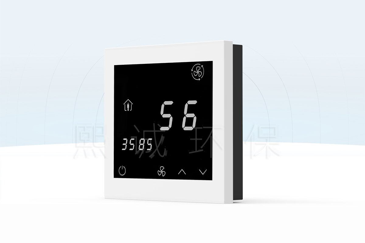
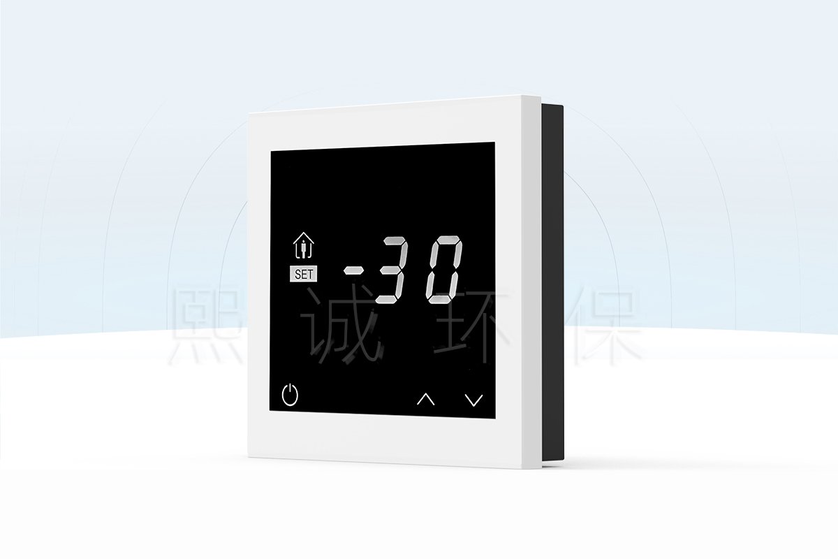
This 86-type touchscreen panel provides local display and setting access for a selected XICHENG airflow or pressure-control configuration. The source records identify two operating presentations: an airflow control panel and a pressure control panel. They use the same display-panel family, so one product page is appropriate when the delivered mode, connected controller and point list are clearly specified.
The panel is an interface, not the sensing and control system by itself. Airflow values require the connected controller, its pressure pickup and its configured calculation. Differential-pressure values require the connected controller and its reference-pressure arrangement. Damper movement requires the actuator and sequence supplied with that controller.
Airflow Display Mode
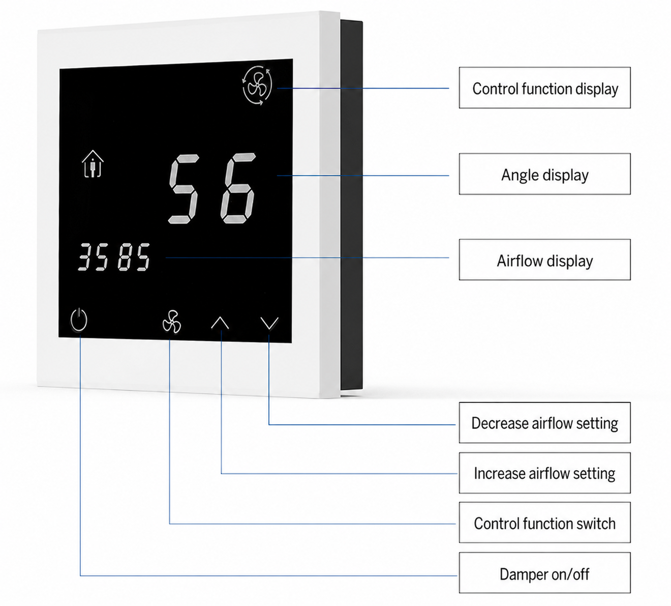
The airflow presentation shows a control-function indicator, an angle value and an airflow value in the source illustration. Its keys are identified for function switching, airflow setting increase/decrease and damper on/off. The displayed value and allowable adjustment range must be defined by the compatible control sequence; the panel does not establish airflow setpoints independently of the controller.
Differential Pressure Display Mode
The pressure presentation is intended to show the applicable airflow and pressure values and to provide local pressure-setting controls. It should be selected where the approved sequence uses differential pressure as a controlled or monitored variable. The project must state the pressure reference, sensor range, alarm requirements and whether local adjustment is permitted.
Purchasing Boundary
Specify whether the panel is required for airflow display, differential-pressure display or both within a configured system. Provide the controller model, protocol, intended point display, local adjustment permissions and mounting location. Do not select it as a substitute for a differential-pressure sensor, VAV controller, actuator or BMS front end.
What a Number on the Screen Means
A numerical display is only useful when the project defines its source and units. For airflow, establish whether the number is calculated by the controller from a terminal pressure pickup, delivered by another approved flow-measurement method, or shown as a configured reference value. For pressure, establish the two reference locations, the direction/sign convention and the normal target. The panel displays the value supplied by the selected configuration; it cannot make a poor sensor location or an incorrect calculation reliable.
This distinction matters during handover. An operator may see a stable number while the connected terminal is not delivering the specified air volume, or may see a pressure value with an opposite sign if the sensor connections or reference convention are reversed. Commissioning documentation should therefore identify the meaning, units and source of every value exposed on the panel.
Key Interface Functions
The panel graphic identifies the local controls and display fields that a user sees at the wall or equipment interface. Their exact availability follows the delivered configuration; a field on the panel should not be interpreted as a promise that every connected system provides the same control function.
Local Controls
The published graphic labels a control-function switch, increase/decrease keys, a damper on/off key, airflow display and angle display. A local interface is useful for operator visibility and approved adjustment, but it must not bypass the safety sequence, BMS interlocks or configured operating limits.
What the Panel Does Not Replace
The panel does not calculate a reliable airflow value without the associated controller and pressure pickup. It does not establish room pressure without a suitable sensor and reference. It does not prove actuator travel or system balance. Those functions remain with the selected controller, connected devices and commissioning procedure.
Address Setting and Controller Integration
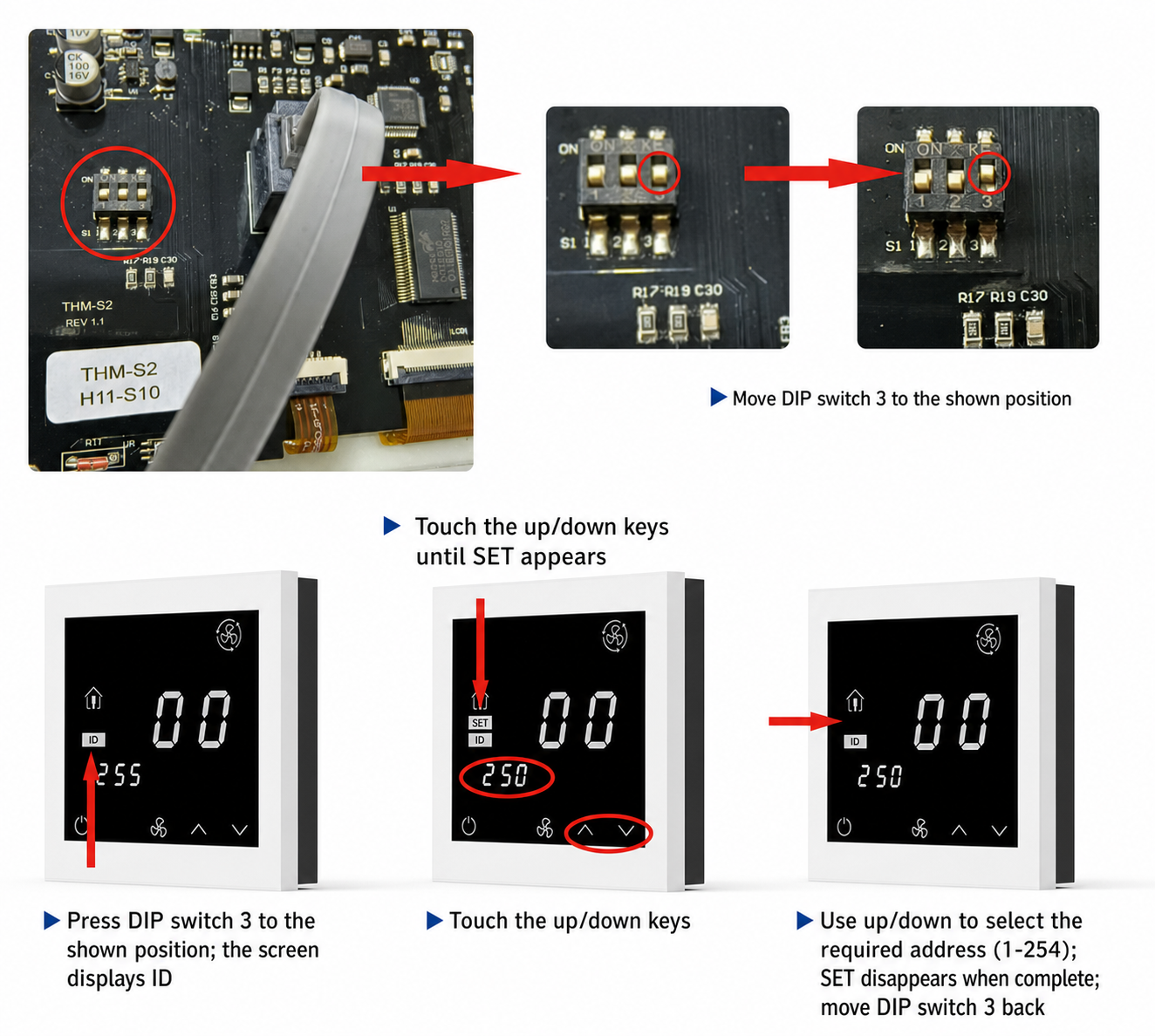
The supplied address-setting instruction identifies DIP switch 3 and a selectable address range of 1-254. Set a unique address only under the approved network plan. The protocol, bus wiring, termination, controller compatibility and point mapping must be verified from the selected system documentation rather than inferred from the address-setting graphic.
Information Required Before Configuration
Provide the panel quantity and location, connected controller, required operating mode, display points, authorized setpoint adjustment, network protocol, address schedule and BMS responsibility. These inputs determine whether the panel is configured for airflow, pressure or another approved display arrangement.
Local Adjustment Permissions
Before enabling local keys, define which users may change a value and what limit applies. A local airflow adjustment may be appropriate for a controlled balancing or operating task, while an uncontrolled change could disturb room balance or a coordinated supply/exhaust sequence. A pressure adjustment may be similarly restricted where pressure is tied to containment, door conditions or fan operation. The delivery record should state whether the panel is display-only, allows limited adjustment, or is used as an authorized service interface.
Display and BMS Responsibilities
The local panel and the BMS should not be assigned contradictory roles. Identify which system owns the active setpoint, which one records alarms and trends, and whether a local change is temporary, persistent or ignored during a supervisory mode. If the BMS writes a value while the panel is also used for adjustment, the sequence must define the priority. This prevents a correctly connected panel from appearing faulty when it is simply following a higher-level command.
Applications and Selection
Use this airflow display panel where a VAV, duct airflow or differential-pressure control system needs a local 86-type operator interface. Typical uses include a local VAV control point, a duct airflow-control arrangement or a room/area pressure-control point. The correct choice depends on what the connected controller measures and controls.
Airflow-Control Applications
For duct airflow control, the panel should be paired with a compatible airflow controller such as the Duct Airflow Controller. Confirm the displayed variable, setpoint limits, actuator operation and local override behavior.
Pressure-Control Applications
For a pressure-control application, pair the panel with the Zone Pressure Controller and a correctly installed differential-pressure sensor. Define the reference locations, normal pressure target, display units and any alarm or override logic before order release.
Multi-Panel Projects
Where several panels are installed on one communications network, give each panel a unique approved address and maintain a location/tag register. The visible device address should be traceable to the controller tag, room or duct point, and intended operating mode. Addressing alone does not establish a valid communications network; cable type, polarity, termination and controller compatibility remain part of the system design.
Installation and Commissioning
Install the panel at an accessible location with the correct electrical back box and cable route. Before handover, verify the intended mode, unique address, controller communication, displayed values, permitted keys and fault behavior. A screen that powers up is not proof that the airflow or pressure value is valid.
Commissioning Checks
- Confirm panel address against the project network schedule.
- Verify each displayed value against the selected controller and field measurement method.
- Check that local increase/decrease and damper commands obey the approved limits and sequence.
- Record controller tag, panel location, operating mode and address for service.
Acceptance Should Test the System, Not Just the Screen
Acceptance should compare the panel reading with the approved controller point and, where relevant, an independent field measurement. Test a permitted local command only under the intended operating mode, then confirm the controller, actuator and BMS respond according to the sequence. For a pressure application, test the normal reference condition and any specified alarm or recovery logic. Do not accept a panel solely because its display illuminates or its keys respond.
Service Information
Keep the final wiring diagram, network address schedule, controller configuration reference, panel location and operating mode with the equipment record. When an operator reports an unexpected value, these items allow service personnel to distinguish a panel issue from a sensor, controller, network, actuator or system-sequence issue.
Frequently Asked Questions
Can one panel display both airflow and pressure?
The source family includes airflow and pressure presentations. The applicable mode and displayed points must be confirmed for the selected controller configuration.
Is it a complete VAV controller?
No. It is a local display and setting interface. The controller, sensor, actuator and control sequence determine actual system operation.
What address range is shown for the panel?
The supplied setting graphic shows an address range of 1-254. Use only the address allocated in the approved network schedule.
Can an operator change the airflow or pressure value freely?
Only if the selected controller configuration and project sequence authorize that adjustment. The panel keys are an interface capability; permitted limits and priority must be defined by the system design.
What should be supplied with an enquiry?
State the connected controller, airflow or pressure mode, display points, local permissions, protocol/network requirement, panel quantity, mounting location and address schedule. Include the control drawing where possible.
Contact the Xicheng Engineering Team
Send the connected controller model, required airflow or pressure display mode, point list, local adjustment requirements, address schedule and mounting quantity. Xicheng can confirm the applicable display-panel configuration and pricing.
Shenzhen Office: No. 34 Zhenxing Road (Shengtaian Heavy Industrial Park B), Loucun, Guangming New Dist, Shenzhen, Guangdong, China
WhatsApp: +86 18126478161
Engineering Mailbox: fanalax34@gmail.com