


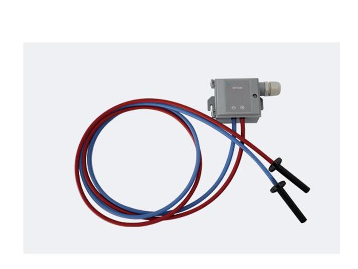
Description
HVAC Differential Pressure Sensor Selection Summary
RPC500 is an air differential pressure sensor for room-pressure systems, HVAC ducts, airflow measurement, filter monitoring, and fan-control feedback. It compares pressure between two defined points and sends the resulting signal to a controller or monitoring system. The sensor does not move an air damper, change fan speed, establish room pressure, or prove airflow without the correct pickup arrangement, scaling, and field verification.
Choose RPC500 When
- The project needs to monitor a small pressure difference between a laboratory room and a defined reference space.
- A ventilation duct requires static-pressure or differential-pressure feedback for monitoring or control.
- Airflow will be derived from differential pressure across a known pickup, valve, flow station, or other characterized device.
- Pressure drop across an air filter must be monitored as an indication of changing resistance.
- A fan or airflow-control sequence needs a pressure signal that can be matched to the selected controller input.
Identify the Measurement Before Selecting the Range
A pressure range cannot be selected reliably until the two measurement points and the purpose of the signal are defined. Room-pressure monitoring compares the controlled space with a corridor, airlock, or other stated reference, whereas filter monitoring compares the upstream and downstream sides of the filter. Duct control may use static pressure at a selected location, while airflow measurement requires a differential-pressure-producing device and its corresponding relationship between pressure and flow. These arrangements can all use an HVAC differential pressure sensor, but they do not share the same expected pressure span, tubing layout, output scaling, alarm limits, or commissioning method.
Key Procurement Decisions
For each sensor tag, identify the application, high- and low-pressure reference points, expected normal and abnormal pressure, intended engineering units, required controller input, power availability, installation environment, tubing distance, mounting location, display or communication needs, and the action taken when the signal is lost or exceeds its limit. If airflow will be calculated, also provide the airflow device, size, coefficient, minimum and maximum flow, and independent balancing method. These details determine the appropriate RPC500 range, output, accessories, and installation arrangement.
Key Product Specifications
RPC500 is designed to measure differential pressure in air and non-corrosive gases. Select the pressure range, accuracy, response, electrical output, power supply, enclosure, ports, and accessories for the actual room, duct, filter, airflow device, or fan-control application. These values belong on the ordered sensor schedule rather than being assumed from the product name.
| Selection Field | RPC500 Product Data | Information to Provide | Selected Configuration |
|---|---|---|---|
| Product model | RPC500 differential pressure sensor | Sensor tag and intended system | Exact supplied model and configuration |
| Measuring media | Air and non-corrosive gases | Gas composition, temperature, humidity, condensation risk, and contamination | Compatibility statement and any use limitation |
| Measurement purpose | Differential pressure and gas-flow-related sensing | Room pressure, duct pressure, pressure drop, or airflow calculation | Measurement mode, reference points, and engineering units |
| Application locations | Rooms and HVAC ducts with small pressure changes | Mounting position, reference-space location, tubing route, and access | Installation arrangement and required accessories |
| Process uses | Airflow detection, filter monitoring, and fan-control monitoring | Expected operating span, alarm limits, airflow device or filter data, and control action | Selected range, scaling, limits, and application notes |
| Electrical interface | Selected for the connected controller or monitoring system | Controller input, power source, wiring distance, display, and communication requirement | Power supply, output signal, wiring terminals, and communication option if applicable |
| Measurement performance | Configured for the required operating span | Required accuracy, response, stability, allowable overpressure, and acceptance method | Applicable performance values and operating conditions |
| Mechanical protection | Selected for the installation environment | Indoor location, panel or duct mounting, dust, moisture, washdown, and service access | Dimensions, mounting, enclosure rating, ports, tubing, and included accessories |
RPC500 Measurement Scope
RPC500 converts a pressure difference in air or a compatible non-corrosive gas into a signal that can be displayed, monitored, alarmed, or used by a controller. Applications include laboratory room pressure, HVAC duct pressure, airflow measurement, filter resistance, and fan-control feedback. The required pressure span and electrical interface vary between these duties, so the ordered configuration must match the actual measurement.
Specifications to Define by Sensor Tag
The final schedule should identify the selected range and whether it is unidirectional or bidirectional, the required output and power supply, engineering units, accuracy and response under stated conditions, allowable static or overpressure, operating temperature and humidity, enclosure and mounting, pressure-port and tubing arrangement, display or communication option, supplied accessories, and calibration or certificate requirements. If any field is decisive for the control sequence, it should appear in both the sensor schedule and the functional test procedure rather than remaining only in a quotation note.
How Differential Pressure Measurement Works
An HVAC differential pressure sensor compares pressure at a high-side reference with pressure at a low-side reference and reports the difference between them. The value is meaningful only when both reference points, tubing connections, engineering units, and signal scaling correspond to the intended measurement. A stable display does not prove that the references are correct, and a reversed tube can change the sign or direction of the result even when the sensor remains electrically functional.
Room-to-Reference Pressure
For laboratory room pressure monitoring, one pickup represents the controlled room and the other represents a defined adjacent space such as a corridor or airlock. The reading describes that specific relationship rather than an absolute property of the room. Supply jets, door sweeps, local turbulence, blocked tubing, or an undefined reference location can bias the signal, while an open door temporarily changes the leakage path that creates the pressure difference. The control narrative should therefore state the reference space, pickup locations, expected sign, door-event behavior, alarm delay, and recovery criterion.
Duct and Filter Pressure Drop
A duct pressure measurement may compare the duct with atmosphere or another duct location, depending on whether the design needs static pressure, pressure loss, or equipment feedback. Filter monitoring instead places the references on opposite sides of the filter so the measured pressure drop can be compared with the specified clean and loaded condition. The sensor detects the pressure difference; it does not determine by itself whether a filter should be replaced, because the alarm threshold must come from the filter and air-system requirements and should be interpreted at the relevant airflow condition.
Airflow Derived from Differential Pressure
Differential pressure can be used to calculate airflow only when a characterized flow pickup, valve, flow station, or other pressure-producing geometry establishes the relationship between pressure and flow. That relationship normally depends on the exact device and size, so the controller or transmitter must use the correct coefficient and engineering units for that device. A coefficient copied from another device can produce a plausible but incorrect airflow value. Commissioning should compare the calculated value with an independent airflow measurement at representative operating points before the signal is used for VAV, CAV, or fan control.
Measurement Is Not the Same as Control
RPC500 provides the measured variable, while a separate controller decides how to respond and an actuator, damper, valve, or fan changes the air system. The usable result therefore depends on the complete chain: pickup location, tubing, sensor configuration, signal wiring, controller scaling, control logic, mechanical authority, and field verification. A fault or mismatch at any link can appear as a sensor problem even when the sensing element is responding normally.
HVAC and Laboratory Applications
Laboratory Room Pressure Monitoring
RPC500 can supply the room-to-reference pressure signal used by a Laboratory Room Pressure Controller. This is a suitable application when the project has already defined the intended positive or negative relationship, reference space, pressure-control method, supply and exhaust response, door logic, and alarm criteria. The sensor alone cannot establish that relationship; adequate airflow capacity, a controllable leakage path, room-level logic, and functional testing are still required.
HVAC Duct Pressure and Fan Control
A duct differential pressure sensor can provide feedback for fan monitoring or a fan-control loop when the pickup location represents the pressure condition the system is intended to regulate. Placement should account for fans, elbows, dampers, coils, transitions, and other sources of local turbulence, since a convenient mounting point may not produce a representative signal. The fan controller or variable-frequency drive must define setpoint, limits, startup behavior, sensor-fault response, and the safe operating range of the connected air system.
Filter Differential Pressure Monitoring
Filter monitoring uses pressure pickups before and after the filter to track the resistance created by the filter and accumulated loading. This arrangement can support maintenance decisions or alarm logic, but the threshold should be based on the selected filter and system operating condition rather than a generic value. If airflow changes substantially, the pressure drop may also change, so the control or maintenance procedure should state whether the reading is evaluated at a defined fan condition, airflow, or operating mode.
Airflow and VAV Measurement
RPC500 can participate in airflow measurement when paired with a compatible differential-pressure pickup and the correct device coefficient. The resulting signal may be used by an Duct Airflow and Pressure Controller or another compatible building-control device. Selection must account for the minimum useful differential pressure, maximum expected condition, controller input, required response, and the airflow range that will be verified during balancing.
Good Fit and Conditions Requiring Review
The product is a good fit for clean-air and non-corrosive-gas applications where the pressure references can be defined and the selected configuration can be matched to the controller and acceptance method. Separate review is required for chemically aggressive vapors, condensing or particle-laden media, outdoor exposure, washdown, unknown static pressure, unusually long tubing, hazardous locations, or any application that requires a certification not documented for the selected RPC500 configuration. RPC500 is not intended for liquid differential-pressure measurement.
Controller and System Integration
Signal and Power Compatibility
The selected RPC500 output must match the receiving controller’s input type, engineering-unit scaling, usable signal range, wiring method, and fault interpretation. Power supply, common reference, shielding, cable routing, and terminal assignment should be reviewed at the same time because a correctly selected pressure range cannot compensate for an incompatible electrical interface. The project wiring diagram should show both the physical terminals and the software scaling used to convert the signal into pressure or calculated airflow.
Relationship to Room and Fume Hood Systems
Within a room-pressure system, RPC500 provides a pressure measurement to a room controller that coordinates supply and exhaust devices. Within a fume hood controller family, a differential-pressure signal may support airflow-related measurement or another defined monitoring function, but it is not interchangeable with a face-velocity sensor or sash-position sensor. Each signal represents a different physical variable, so the control narrative and point list must identify what the measurement means and which controller owns the response.
What the Sensor Does Not Control
RPC500 does not generate airflow, regulate a fan, position a damper, balance a room, determine filter service life, or certify fume hood containment. Those actions belong to controllers, actuators, airflow devices, maintenance criteria, and acceptance procedures elsewhere in the system. A sensor reading can support an alarm or control decision only when the reference points, range, scaling, expected operating state, and response to a failed signal have been defined.
Selection and RFQ Information
| RFQ Field | Information to Provide | Why It Changes the Selection | Specified Result |
|---|---|---|---|
| Measurement task | Room pressure, duct pressure, filter drop, fan monitoring, or airflow calculation | Defines the reference arrangement and required signal behavior | Recommended RPC500 configuration and application notes |
| Pressure condition | Expected normal, minimum, maximum, abnormal, and possible static or overpressure condition | Establishes the usable range and protection requirement | Selected measuring range and stated operating limits |
| Media and environment | Gas composition, temperature, humidity, condensation, dust, chemicals, indoor/outdoor location, and enclosure exposure | Determines compatibility and mechanical protection | Compatibility statement, enclosure, mounting, and exclusions |
| Pressure references | High and low pickup locations, tubing length, route, elevation, and access | Affects sign, stability, response, maintenance, and condensate risk | Pickup, port, tubing, and installation requirements |
| Controls interface | Power, input type, signal range, engineering units, controller model, display, alarm, and communication needs | Defines electrical and software compatibility | Output, power, wiring, scaling, and interface schedule |
| Acceptance | Required accuracy, response, calibration evidence, test method, alarm limits, and handover documents | Defines the performance and documents that must appear in the purchase specification | Applicable values, conditions, certificates, and functional test scope |
| Commercial | Sensor tags, quantity, accessories, spare parts, destination, and delivery timing | Defines the order scope and logistics | Itemized quotation, exclusions, lead time, and price |
Selection Sequence
Begin with the physical measurement and reference points, then establish the expected pressure span and abnormal condition before selecting the electrical interface. After the sensor is matched to the controller, review mounting, tubing, environmental protection, calibration, alarm logic, and the field test that will prove the signal. Reversing this sequence and choosing an output or enclosure first can produce an electrically convenient device that cannot resolve the required pressure condition or survive the installed environment.
What XICHENG Will Define in the Quotation
The quotation will identify the proposed RPC500 measuring range, pressure direction, output, power, performance values and conditions, enclosure and mounting, ports and tubing accessories, wiring requirements, compatibility boundary, quantity, documentation, exclusions, delivery, and price. Values that depend on the final room, duct, filter, airflow device, or controller will be tied to the selected configuration.
Installation and Commissioning
Pressure Pickup and Tubing Arrangement
Locate each pickup where it represents the intended pressure rather than a local jet, eddy, door sweep, fan discharge, elbow, or damper disturbance. Route the high- and low-side tubes so they remain identifiable, accessible, and protected from kinks, leakage, blockage, accidental reversal, and condensation. Follow the RPC500 mounting and port instructions supplied with the selected sensor rather than relying on a competitor manual or visual assumption.
Zero, Polarity, Scaling, and Functional Checks
Before enabling control or alarms, inspect the tubing and references, verify the zero condition according to the commissioning procedure, confirm pressure polarity, and check that the controller displays the correct engineering units and scale. Apply or create a known operating change and verify that the indicated value moves in the expected direction. For airflow use, compare the calculated flow with an independent measurement; for room pressure, test representative door and airflow states; for filter monitoring, confirm the upstream and downstream references and alarm logic.
Handover Records
The handover package should include the sensor tag, installed configuration, range, output, power, reference-point drawing, tubing route, controller scaling, alarm limits, calibration or verification record, and final measured results. These records allow a maintenance technician to distinguish sensor drift from reversed tubing, a blocked pickup, changed room leakage, altered fan operation, an incorrect flow coefficient, or a controller-scaling error.
Application Boundaries and Custom Configuration
Suitable Media and Conditions
RPC500 is intended for air and non-corrosive gases in room, HVAC duct, airflow, filter, and fan-monitoring applications. Select the range, signal, enclosure, mounting, accessories, and documentation from the actual measurement and installed conditions rather than treating the model as one fixed package.
Conditions Requiring Separate Review
Do not assume compatibility with corrosive vapors, combustible gases, liquids, condensation, heavy particle loading, outdoor weather, washdown, hazardous areas, high static pressure, or certification-controlled applications. The sensor also does not replace a differential-pressure switch when a project specifically requires a certified switching function, and it should not be represented as a complete VAV Butterfly Damper, fan controller, room controller, or safety system.
Frequently Asked Questions
What does the RPC500 differential pressure sensor measure?
RPC500 measures the pressure difference between two defined points in air or a non-corrosive gas. XICHENG identifies room and HVAC duct pressure changes, airflow-related measurement, filter monitoring, and fan-control monitoring as applicable uses.
Can RPC500 be used as a room differential pressure sensor?
Yes, it is shown within XICHENG laboratory room pressure-control configurations. The project must still define the controlled room, reference space, expected pressure direction and span, pickup locations, alarm behavior, and the controller that responds to the signal.
Can differential pressure be converted into airflow?
Yes, when the pressure is measured across a characterized flow pickup, valve, flow station, or other known geometry. The correct device coefficient, engineering units, and independent airflow verification are required; the sensor alone does not establish the pressure-to-flow relationship.
Can it monitor HVAC filter loading?
Yes. The high and low references are placed on opposite sides of the filter, and the measured pressure drop can support an alarm or maintenance decision. The filter supplier and air-system design should define the applicable evaluation condition and limit.
Which pressure range and output should I select?
Select them from the expected normal and abnormal pressure, required resolution and response, controller input, power supply, wiring, and acceptance criteria. RPC500 configurations are matched to the application, so the ordered range and output must be identified in the quotation.
Does RPC500 include Modbus or a local display?
Do not assume either feature from the model name. State the required analog or digital interface, display, communication protocol, and point list in the RFQ so XICHENG can confirm whether the selected configuration supports them.
Can it measure corrosive gas or liquids?
RPC500 is intended for air and non-corrosive gases. Corrosive, condensing, contaminated, combustible, or liquid media require a separate compatibility and product review before selection.
Contact the Xicheng Engineering Team Today
Send the sensor tag list, measurement purpose, high- and low-pressure reference points, expected operating and abnormal pressure, media and environmental conditions, controller input and power, tubing and mounting arrangement, accuracy and response requirement, alarm or control sequence, quantities, and destination. XICHENG will prepare a proposed sensor configuration, range and interface schedule, installation requirements, and quotation.
Shenzhen Office: No. 34 Zhenxing Road (Shengtaian Heavy Industrial Park B), Loucun, Guangming New Dist, Shenzhen, Guangdong, China
WhatsApp: +86 181 2647 8161
Engineering Mailbox: fanalax34@gmail.com