


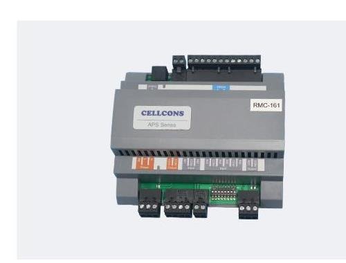
Description
Laboratory Room Pressure Controller Overview
A laboratory room pressure controller keeps the supply and exhaust sides of a room working toward the same pressure objective. RMC161 monitors the selected combination of room differential pressure, supply airflow, exhaust airflow, temperature, humidity, and door status, then adjusts the controlled supply and exhaust VAV air dampers or valves. This coordinated approach is intended for laboratories, animal rooms, and similar spaces where a stable pressure relationship to an adjacent corridor or reference area matters.
The controller is configured for the actual room rather than sold as a universal pressure package. The pressure target, reference location, normal and emergency airflow states, leakage path, door operation, process exhaust, controlled airflow devices, alarms, and acceptance tests determine how the control loop must operate. The room schedule and sequence therefore define the supplied controller configuration instead of one fixed airflow or pressure range applying to every project.
Choose This Controller When
- The room must maintain a defined positive or negative pressure relationship to an adjacent space.
- Supply and exhaust airflow must be coordinated instead of balanced once and left as two independent branches.
- Door opening can disturb the room and its open/closed state needs to be included in the pressure-control sequence.
- The project needs monitoring of room pressure together with supply airflow, exhaust airflow, temperature, or humidity.
- The selected VAV air dampers or valves provide enough controllable airflow range and available pressure to correct expected disturbances.
Information Needed Before Selection
Start with the room pressure relationship diagram, supply and exhaust schedules, equipment and fume hood exhaust, door quantity and operation, room construction, expected leakage, and normal, occupied, unoccupied, alarm, and emergency modes. Also identify the pressure sensor and reference point, airflow-measurement method, controlled air dampers or valves, actuator signals, local display requirements, alarms, BMS points, and commissioning responsibility. These inputs determine whether direct pressure control, airflow tracking with pressure trim, or another sequence is appropriate.
Control and Monitoring Scope
RMC161 is a room differential-pressure controller, not merely a pressure transmitter. It monitors the room and airflow conditions used by the selected sequence and regulates the supply and exhaust airflow devices that influence the pressure relationship. The table shows the available functions and the information needed to configure them.
Key Product Functions
| Selection Field | RMC161 Function | Information to Specify |
|---|---|---|
| Primary product role | Laboratory room pressure controller for pressure-gradient control | Positive/negative relationship and reference space |
| Applications | Laboratories and animal rooms | Process, occupancy, risk, and governing requirements |
| Pressure monitoring | Monitors room differential pressure | Range, accuracy, reference point, tubing, and calibration |
| Airflow monitoring | Supports supply-airflow and exhaust-airflow monitoring | Measurement device, range, signal, location, and commissioning method |
| Airflow control | Adjusts supply and exhaust VAV air damper or valve opening | Device size, range, available pressure, actuator, command, feedback, and fail position |
| Environmental monitoring | Supports room temperature and humidity monitoring | Sensor type, range, location, displayed values, alarms, and BMS use |
| Door status | Supports room door open/closed status monitoring | Switch type, number of doors, logic, timing, and alarm behavior |
| Configuration | Made to order for the selected control sequence | Power, I/O, communication, enclosure, wiring, point list, and documentation |
What the Controller Does Not Define by Itself
The product name does not establish a universal pressure range, accuracy, airflow capacity, response time, communication protocol, enclosure rating, or supported room size. Those values depend on the selected sensors and airflow devices, the room leakage characteristics, the available duct pressure, and the configured control sequence. Specify the controller revision and all connected devices by room tag.
Made-to-Order Configuration
Non-standard configuration is central to this product. One room may use a controlled exhaust branch and a stable supply branch; another may require both supply and exhaust control, multiple process exhaust inputs, a local display, and door-state logic. The controller is configured around those requirements, but the room still needs sufficient mechanical capacity and a measurable pressure reference for the selected sequence to work.
How Laboratory Room Pressure Control Works
Room differential pressure is the result of airflow imbalance and leakage between the controlled room and its surroundings. RMC161 does not create that relationship on its own. It commands the available supply and exhaust airflow devices so the complete ventilation system can maintain the required pressure objective while room demand and door conditions change.
Pressure-Gradient Control Loop
The pressure sensor compares the room with a defined reference space. When measured pressure moves away from the setpoint, the controller changes the commanded opening of the selected supply or exhaust VAV device according to the configured sequence. The resulting airflow change alters the room balance and moves the pressure relationship back toward its target. Stable control requires a sensor range suited to the small pressure difference, usable actuator resolution, adequate airflow authority, and a response that does not overcorrect.
Supply and Exhaust Control Authority
The controlled devices must cover the room’s minimum, normal, maximum, and emergency airflow states without operating permanently at their limits. If an exhaust damper is already fully open or the supply branch lacks available pressure, the room controller cannot correct a pressure error by software alone. Device sizing should therefore consider fan performance, duct losses, terminal pressure, process exhaust, diversity, and the airflow offset needed to support the intended leakage direction.
Door-State Disturbance Management
Opening a door temporarily increases the leakage opening and can collapse or reverse the measured pressure difference even when the airflow system is operating correctly. RMC161 supports door open/closed status monitoring so the sequence can distinguish a known access event from a persistent control failure. The project should define whether control output is held, limited, temporarily adjusted, or allowed to respond normally during the open-door period, and when an alarm becomes valid after the door closes.
Pressure Control Versus Airflow Tracking
Direct pressure control responds to the measured room relationship. Airflow tracking coordinates measured supply and exhaust quantities, often maintaining a required airflow offset, while pressure provides verification or trim. Rooms with changing process exhaust, multiple hoods, frequent door use, or less predictable leakage may need both types of information. RMC161 can monitor the relevant pressure and airflow conditions, but the selected strategy and priority between loops must be defined before configuration.
Monitoring Inputs and System Interfaces
The value of a room pressure controller depends on the quality of the measurements and controlled devices connected to it. Each input should have a defined engineering purpose, and each output should be tied to an identified branch, actuator, operating range, and failure response.
Pressure and Airflow Measurements
Room pressure measurement requires two clearly defined pressure locations, protected pickup points, suitable tubing, and access for zero verification. Supply and exhaust airflow measurements require compatible sensors or airflow stations, correct straight-run or pickup conditions, and field calibration against the balancing method. The controller can use these values only as accurately as the installed sensing chain provides them.
Temperature and Humidity Monitoring
RMC161 supports monitoring of room temperature and humidity as part of the room-control information set. These measurements can help operators and the building management system understand room conditions, but they should not be assumed to provide full environmental control unless the HVAC sequence, sensors, heating/cooling equipment, humidification or dehumidification equipment, and controller I/O are specifically designed for that duty.
Door Status and Local Display
A door switch provides a discrete indication that helps the control sequence interpret pressure disturbances. A local room panel may display configured values such as room pressure, temperature, humidity, supply airflow, and exhaust airflow. Displayed points, adjustment permissions, alarm acknowledgement, access levels, and communication with the field controller are defined for the project; they are not implied by the controller model alone.
Controlled Air Dampers and Valves
The supply and exhaust devices may be VAV air dampers, Venturi air valves, or another compatible airflow-control assembly selected for the air stream and required performance. Confirm nominal size, airflow range, pressure condition, material, actuator power, command and feedback signals, rotation or stroke, failure position, and installation orientation. For corrosive exhaust, review every exposed component rather than relying only on a general body-material label.
Applications and Product Fit
Laboratory Pressure-Control Applications
The laboratory room pressure controller can be configured for rooms that must remain negative to contain an air stream or positive to protect a cleaner space, provided the ventilation design can produce that relationship. Typical project inputs include fume hood exhaust, equipment exhaust, make-up air, general exhaust, occupancy schedules, and door events. The controller coordinates the selected room-level devices; it does not replace fume hood containment controls or equipment-specific exhaust interlocks.
Animal-Room Applications
Animal rooms may require stable pressure direction while ventilation rates, heat loads, door use, and cleaning states change. RMC161 can use the selected airflow, differential-pressure, environmental, and door-status inputs within the room sequence. The complete design must still address required air changes, filtration, redundancy, sanitation, alarm management, facility standards, and any animal-care or biosafety requirements applicable to the project.
Product Boundaries and Related Controllers
RMC161 Versus RPC500
The HVAC differential pressure sensor measures a pressure or airflow-related signal for air and non-corrosive gases. RMC161 is the control layer that uses selected measurements to adjust supply and exhaust airflow devices. A pressure sensor can be part of the RMC161 system, but it does not perform the room-control sequence by itself.
RMC161 Versus ZPC211
The differential pressure controller integrates a compact rotary actuator and supports configured pressure or airflow control at an individual air damper. RMC161 is positioned around the room-level relationship, including supply and exhaust monitoring and door-state information. Use the room controller when the sequence must coordinate multiple room conditions rather than regulate one actuator from one field-control point.
RMC161 Versus RMC2102
RMC161 focuses on room differential-pressure control with supply/exhaust, environmental, and door-state monitoring. The laboratory room controller based on RMC2102 provides a broader field-control option for room pressure-gradient and supply/exhaust airflow coordination. Choose between them from the point list, control methods, fan-state interfaces, communication, and required system architecture rather than from model numbering alone.
Conditions That Require Project Review
Review the complete design when a room has multiple doors, airlocks, several fume hoods, high or rapidly changing process exhaust, uncertain leakage, smoke or fire-control interfaces, critical redundancy, hazardous exhaust, or a defined containment or cleanroom classification. A room pressure controller supports the ventilation sequence but does not certify containment, room classification, biosafety performance, or code compliance by itself.
Selection, Installation, and Commissioning
Selection Data by Room Tag
| Data Group | Information to Provide | Why It Matters |
|---|---|---|
| Room relationship | Controlled room, reference space, positive/negative direction, pressure target, alarm limits | Defines the measurement and control objective |
| Airflow schedule | Supply, general exhaust, fume hood, equipment exhaust, minimum, normal, maximum, emergency states | Defines control range and required authority |
| Room and doors | Room layout, volume, construction, leakage information, door quantity, swing, frequency, and switches | Defines disturbances and pressure response |
| Sensors | Pressure, airflow, temperature, humidity, locations, ranges, outputs, accuracy, calibration | Defines measurement quality and I/O |
| Controlled devices | Air damper/valve type, size, airflow range, available pressure, actuator, command, feedback, fail position | Defines available control action |
| Controls | Modes, alarms, local display, BMS points, communication, interlocks, failure and recovery sequence | Defines controller configuration and acceptance |
Installation Coordination
Mount the controller where its enclosure, terminals, service access, and environmental limits can be maintained. Install pressure pickups away from drafts and local turbulence, protect tubing from kinks and blockage, and identify high/low or room/reference connections clearly. Coordinate airflow sensors with the required duct geometry. Verify each air damper or valve can travel freely and that actuator direction, command, feedback, and failure position match the control drawings.
Commissioning and Acceptance
Commissioning should begin with sensor zero and calibration checks, point-to-point I/O verification, actuator stroke checks, and airflow balancing. Test normal and setback states, pressure setpoint response, supply and exhaust tracking, door opening and closing, alarm delays, fan failure, communication loss, sensor failure, power interruption, emergency operation, and recovery. Record measured pressure, airflow, output position, alarm state, and final settings for each room tag.
Quotation Scope
The quotation should list the RMC161 configuration, required sensors and local panel, controlled airflow devices and actuator interfaces, I/O and communication scope, power and enclosure information, installation assumptions, commissioning responsibilities, documentation, quantity, delivery, and pricing. It should also identify any values that still depend on room data or the final control sequence.
Related Laboratory Pressure-Control Products
Use the HVAC Differential Pressure Sensor when the project needs pressure or airflow measurement without room-control logic. Use the Differential Pressure Controller when one compact controller-actuator assembly will regulate an individual air damper. Use the VAV Box Controller for terminal airflow and zone-temperature control. Evaluate the Laboratory Room Controller when the broader RMC2102 field-controller architecture is required.
Frequently Asked Questions
Is RMC161 a pressure sensor?
No. RMC161 is a laboratory room pressure controller. It uses pressure and other configured measurements to command supply and exhaust airflow devices. A compatible differential-pressure sensor and correctly installed room/reference pickups are still required.
Can it control both positive- and negative-pressure rooms?
The controller can be configured around the required pressure relationship, but suitability depends on the airflow arrangement, sensor reference, available control authority, leakage path, alarms, and sequence. State the required pressure direction and operating states for each room.
Why does the controller monitor supply and exhaust airflow?
Room pressure is produced by the balance between air entering and leaving through controlled branches and leakage paths. Supply and exhaust measurements help the sequence understand available airflow, track disturbances, and avoid relying on one pressure value without knowing whether a branch has reached its limit.
How is door opening handled?
RMC161 supports door open/closed status monitoring. The project defines how the controller behaves during the door event, how long pressure recovery is allowed, and when an alarm becomes valid. Door logic should prevent unnecessary output hunting without masking a persistent pressure-control problem.
Does the controller include air dampers, sensors, and a display?
Included equipment follows the ordered scope. A complete room solution may require pressure and airflow sensors, supply and exhaust VAV air dampers or valves, actuators, a local display, door switches, power supplies, wiring, BMS integration, balancing, and commissioning.
What must be tested before handover?
Verify sensor calibration, room/reference tubing, airflow readings, actuator travel, operating states, pressure response, door events, alarms, fan and sensor failures, communication loss, emergency logic, and recovery. Final settings and measured results should be recorded by room tag.
Contact the Xicheng Engineering Team Today.
Send the room pressure relationship diagram, supply and exhaust schedules, process and fume hood exhaust, door information, room layout and leakage details, selected sensors and airflow devices, operating modes, alarms, BMS point list, quantity, destination, and required commissioning scope. XICHENG will recommend an RMC161 room pressure controller configuration and provide the applicable interfaces, documentation, specifications, items requiring confirmation, and pricing.
Shenzhen Office: No. 34 Zhenxing Road (Shengtaian Heavy Industrial Park B), Loucun, Guangming New Dist, Shenzhen, Guangdong, China
WhatsApp: +86 181 2647 8161
Engineering Mailbox: fanalax34@gmail.com