


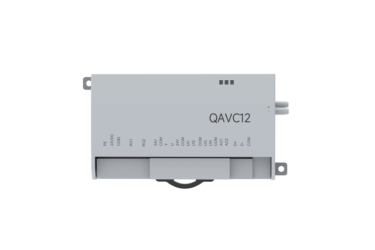
Description
This standalone duct airflow and pressure controller is intended for laboratory supply, exhaust, and room-pressure branches that require a separately selected rotary or linear actuator. It receives the configured airflow or pressure demand, measures the differential-pressure signal from the approved pickup, and sends a modulating command to the actuator. The separate-controller architecture places it within XICHENG’s laboratory airflow controls and actuators range without making the actuator or airflow device part of the controller itself.
- Separate-controller architecture for retained, specified, remotely mounted, or project-selected actuators
- Built-in differential-pressure sensing for measured VAV, fixed-airflow, or configured room-pressure control
- 0-10 V actuator command, actuator-position feedback, and measured-airflow feedback interfaces
- Room sensor and door-contact inputs, local-panel connection, relay functions, and Modbus RTU communication
The controller does not include the actuator, valve or damper, airflow pickup, pressure tubing, room sensor, or complete supervisory sequence unless those items are explicitly listed in the approved supply scope. Final interfaces are assigned for each valve tag and external-actuator package.
Product Overview
A Standalone Controller for a Measured Airflow Loop
This controller sits between the project demand and the actuator that moves the selected airflow device. The demand may originate from an analog airflow setpoint, a configured room differential-pressure signal, or a Modbus command. The built-in airflow-sensing function reads the differential-pressure signal produced by the approved pickup arrangement. Control logic compares that measured condition with the active demand and changes the actuator command until the branch reaches the intended operating state.
This is not position-only damper control. Actuator-position feedback confirms mechanical movement, while the differential-pressure airflow signal closes the flow loop and helps distinguish linkage or actuator faults from pickup, tubing, pressure, valve, or calibration problems.
Why the External-Actuator Architecture Matters
The separate actuator is the defining product decision. The controls schedule can specify the controller and its sensing/I/O, while the mechanical schedule selects the device that actually produces rotary or linear movement. This arrangement allows a butterfly damper, Venturi mechanism, retrofit valve, or project-preferred actuator to be reviewed on its own mechanical requirements. It also prevents a single integrated controller-actuator envelope from deciding the actuator brand, output, motion, mounting, or fail behavior before the valve is known.
The available 0-10 V command and position-feedback functions do not make every actuator compatible. The tag schedule must confirm signal ranges, common reference, supply, motion, output, travel, run time, direction, failure response, and the actual rotary torque or linear thrust required by the valve.
Product Boundary and Project Responsibility
The controller supplies measurement and control functions; it does not create airflow. The fan and duct system establish available pressure, the valve creates a controllable restriction, the measurement element produces the differential-pressure relationship, and the actuator moves the mechanism. Pressure tubing, pickup orientation, coefficient setup, sensor zero, valve sizing and field balancing determine whether the controller can calculate and maintain a useful airflow value.
For room-pressure participation, it can receive a room-pressure signal and door-contact state, but it does not replace the pressure sensor, door hardware, other supply/exhaust devices, supervisory logic, alarms, BMS coordination, or final room test. The approved sequence must assign airflow and pressure ownership and define door, emergency, sensor-failure, and network-failure behavior.
Product Selection Summary
First Decide Between Integrated and Separate Actuation
Choose the separate-controller architecture when an existing actuator will be retained, a consultant has specified an actuator manufacturer, the valve requires a different motion or output, the controller must be mounted away from the valve, or controls and mechanical components need independent replacement. If one compact package satisfies valve output, motion, wiring, and service-space requirements, compare an integrated controller-actuator before freezing the external design.
Compare complete installed scope, including enclosure, actuator, power, cable, linkage, brackets, panel, terminal work, access, and commissioning. Record which components are new, retained, included, or supplied by others.
Then Prove the External Actuator and Measurement Path
Actuator command and position feedback alone do not prove a workable assembly. Confirm whether the actuator accepts the selected 0-10 V command, what signal it returns, whether common references are compatible, how it is powered, and what happens when command, feedback, controller power, or network is lost. Mechanical review must confirm torque or thrust at actual valve load, angle or stroke, direction, mounting, end stops, linkage, access, and operating time.
Also state the valve and size, measurement element, pressure-tap orientation, tubing route, coefficient, design airflow, and available pressure. For room-pressure operation, add sensor range/location, door logic, supply/exhaust relationship, and loop priority. Do not schedule the controller while the actuator or measurement chain remains an unnamed allowance.
Define The Complete Controller And Actuator Package
The quotation identifies more than a product code and unit price. It states the controller version, power arrangement, enabled input/output functions, actuator command and feedback, compatible panel and communication interfaces, terminal or wiring document, valve and pickup dependencies, included components, optional components, and work provided by others. Linking these details to each valve tag prevents the controller price from being separated from the configuration it is intended to operate.
The final drawing and point list define the customized configuration. Changes to valve size, actuator, sensor, panel, BMS protocol, failure state, or room-pressure sequence may change the terminals, setup, and commissioning procedure, so update the configuration documents when these inputs change.
Key Specifications
Controller Functions and Interfaces
The table defines controller-level functions. It does not include the valve, actuator, airflow pickup, room sensors, local panel, transformer, or project wiring unless those items are named in the approved supply schedule.
| Specification | Product Data |
|---|---|
| Product architecture | Standalone airflow/pressure controller for a separately selected external actuator |
| Controller supply | 24 VDC |
| Wiring power reference | External 24 VDC, 3 A supply shown in the wiring diagram; this is not stated controller consumption |
| Airflow sensing | Built-in airflow sensor / differential-pressure airflow-detection function |
| Airflow operation | Measured airflow control using the configured demand and airflow relationship |
| Pressure operation | Room differential-pressure signal can participate in the configured control sequence |
| Analog input functions | Room differential pressure, room temperature, room humidity and external-actuator position feedback |
| Analog output functions | 0-10 V external-actuator command and 0-10 V airflow feedback |
| Digital input function | Door-magnetic-switch / door-contact state for the configured room-pressure sequence |
| Switching functions | Lighting and operating/exhaust-related status functions; final output count and assignment are version-specific |
| Local panel interface | RJ12 connection for the matching independent control panel |
| Network | EIA-485 / RS-485 communication |
| Protocol | Modbus RTU support |
| Compatible motion | Project-selected rotary or linear actuator |
| Compatible airflow devices | Butterfly damper or Venturi air valve with approved measurement and mechanical interfaces |
| Configuration basis | Valve tag, airflow/pressure sequence, pickup, actuator, sensors, I/O, panel, network and fail state |
Electrical Values and Their Limits
The 24 VDC, 3 A notation belongs to the external supply shown on the wiring diagram. It is not the controller’s stated power consumption and should not be used alone to size a project circuit. Connected sensors, panel, actuator, relay loads, cable length, protection, and voltage drop require an approved electrical schedule. Relay ratings remain tied to the matching drawing revision and terminal group.
Likewise, 0-10 V describes available analog functions but does not prove that every actuator or BMS point can connect directly. The signal schedule must identify direction, range, scaling, common reference, load, isolation, fail value, update behavior, and responsibility.
Fields That Remain Project-Specific
Enclosure dimensions, controller consumption, airflow and differential-pressure ranges, control accuracy, response time, environmental limits, enclosure protection, certification, and the communication register map must be confirmed for the supplied revision before entering a contractual schedule. Valve and actuator size, material, torque or thrust, travel, action time, leakage, pressure, and installation data remain separate product fields.
Switching-output descriptions and terminal groupings vary by documentation revision. Before fabrication or site wiring, approve the current terminal schedule, relay ratings, common groups, and intended use of every output.
Control Modes and Signal Ownership
Measured Airflow Control
In an airflow-control loop, the active setpoint represents the required branch flow rather than a requested actuator angle. The controller reads the airflow-related differential pressure, applies the configured airflow relationship, compares the calculated value with demand, and changes the 0-10 V actuator command. The external actuator moves the butterfly blade or Venturi mechanism, which changes the measured condition and closes the loop.
The setpoint may come through the configured analog path or Modbus. Define minimum, normal, maximum, and emergency states in engineering units, then document scaling, limits, overrides, write permissions, and invalid-signal behavior. The approved sequence must define priority among analog, network, and local-panel demands.
Room Differential-Pressure Participation
The room differential-pressure input allows the controller to participate in a pressure sequence by changing the assigned supply or exhaust airflow device. The door-contact input can inform that sequence when an open door makes the normal pressure target temporarily unreliable. A useful design defines the target pressure, sensor range and location, controlled device, airflow limits, door-open behavior, alarm delay, recovery logic and interaction with other supply or exhaust branches.
This input does not coordinate an entire laboratory room. Where several valves, fume hoods, fans, or transfer paths affect pressure, identify the supervisory controller and the variable owned by each branch. Commissioning must verify branch airflow and final room response under planned door and operating states.
Temperature, Humidity and Position Inputs
Available analog-input functions include room temperature, room humidity, and actuator position. Treat the temperature and humidity channels as configurable inputs rather than complete environmental-control loops; the approved program, signal ranges, setpoints, and controlled outputs must define their use.
Actuator-position feedback supports diagnostics by exposing reversed direction, stalled movement, or linkage failure when compared with measured airflow. Position remains a mechanical-state signal; expected position can coexist with incorrect flow caused by pressure, blockage, pickup, tubing, valve, or calibration conditions.
Controller Interface Map
| Interface Group | Controller Function | Project Use | Confirm Before Wiring |
|---|---|---|---|
| Analog input | Room differential pressure | Pressure demand or supervisory input | Range, scaling, polarity, location and control ownership |
| Analog input | Room temperature | Configured monitoring or control input | Sensor type, range, program and controlled output |
| Analog input | Room humidity | Configured monitoring or control input | Sensor type, range, program and controlled output |
| Analog input | Actuator position feedback | Mechanical-state feedback and diagnostics | Signal range, direction, common and loss behavior |
| Analog output | 0-10 V actuator command | Commands a compatible external actuator | Input range, load, common, direction and fail state |
| Analog output | 0-10 V airflow feedback | Reports measured airflow to panel or BMS | Engineering-unit scaling and recipient input requirements |
| Digital input | Door-contact state | Door-event logic in a pressure sequence | Contact state, debounce, priority, delay and recovery |
| Switching output | Lighting and operating/status functions | Project-assigned relay actions | Current terminal schedule, common group, rating and load interface |
| Panel | RJ12 local-panel interface | Local display, setpoint or operation where configured | Compatible panel, cable, distance, power and supplied scope |
| Network | EIA-485 / Modbus RTU | BMS command, feedback and diagnostics | Address, baud, parity, register map, permissions and timeout state |
Each signal should have one named owner. The approved point list should show source, destination, engineering units, range, normal value, alarm limit, override priority and failure state. This prevents a local panel, analog signal and BMS command from issuing competing demands without a defined arbitration rule.
External Actuator Control
Electrical Compatibility Comes Before Brand Compatibility
The controller can work with different actuator brands, but brand is not a wiring specification. The actuator must accept the 0-10 V command and provide compatible position feedback. Confirm supply, common reference, signal range, input load, isolation, direction, feedback scaling, startup behavior, and the response to loss of command, controller power, or actuator power.
The controller and actuator may use separate supplies. The electrical design must address common reference, isolation, grounding, cable routing, and fault propagation. The approved schematic should identify each common, feedback reference, and any relay, interface module, or protected circuit; there is no universal wiring arrangement for every actuator.
Mechanical Selection Is Valve-Specific
Rotary Actuators
A rotary actuator is appropriate when the damper shaft or valve mechanism requires angular movement. Selection begins with shaft dimensions, required rotation, direction and available mounting space, then checks breakaway and running torque at the maximum expected differential-pressure load. The bracket and anti-rotation arrangement must prevent body movement, while shaft engagement and end limits must avoid slip or forcing the valve past its mechanical stops.
Linear Actuators
A linear actuator is appropriate when the airflow device uses a translating cone, rod or linkage. Specify required thrust in both directions, usable stroke, linkage geometry, end positions, side-load control and access for adjustment. The actuator must move the mechanism through the approved control range without binding, bottoming out or transferring damaging load into the valve body. A nominal stroke alone does not confirm compatibility.
External Actuator Approval Matrix
| Decision Field | Rotary Actuator | Linear Actuator | Required Approval Evidence |
|---|---|---|---|
| Mechanical output | Torque at the actual valve load | Thrust in both travel directions | Valve calculation, manufacturer data or approved selection record |
| Motion | Required angle and direction | Required usable stroke and direction | Valve drawing with open/closed and control-range positions |
| Connection | Shaft size, clamp and anti-rotation bracket | Rod end, linkage, guides and mounting bracket | Dimensioned mechanical interface drawing |
| Command | Compatible 0-10 V input | Compatible 0-10 V input | Actuator electrical data and signal schedule |
| Feedback | Position signal with defined scaling | Position signal with defined scaling | Feedback range, common reference and endpoint check |
| Operating time | Selected for the approved airflow/pressure sequence | Selected for the approved airflow/pressure sequence | Sequence review and field stroke test |
| Failure response | Hold, drive or return state as specified | Hold, drive or return state as specified | Power-loss and signal-loss cause-and-effect record |
| Environment | Location, access and exposure reviewed | Location, access and exposure reviewed | Installation drawing and actuator environmental rating |
The controller page intentionally does not publish a default torque, thrust, stroke or action time. Those values belong to the selected external actuator and valve tag. The quotation should identify the proposed actuator or list the interface requirements when the actuator is supplied by another party. Either approach must close the command, feedback, power, mechanics and fail-state fields before production.
Airflow Measurement and System Compatibility
The Measurement Chain Must Be Approved as One Loop
Built-in airflow sensing is one part of the measurement chain. The airflow device or pickup creates a differential-pressure signal; correctly routed high- and low-pressure tubing carries it; the controller applies the approved coefficient; and field balancing compares the calculated value with an independent airflow measurement. Reversed tubing, a wrong coefficient, disturbed flow, or pressure-line leakage can produce a believable but incorrect result.
Identify the pickup, duct or valve size, pressure-port orientation, tubing, flow states, coefficient source, setup units, and balancing method. Size-specific airflow data belongs to the valve/pickup assembly and must not be generalized into a controller airflow range.
Butterfly damper Applications
A VAV butterfly damper uses a rotating blade to change duct resistance. The external actuator must match shaft, angle, and torque, while the pickup must provide measurement data for the selected damper and installation. Use measured airflow for the control loop and position feedback for mechanical confirmation.
Confirm whether the pickup is integrated, installed upstream, or separate. Because transitions, elbows, takeoffs, silencers, and fans can disturb the signal, follow the valve supplier’s approved installation and balancing method rather than an unsupported generic straight-duct rule.
Venturi Air Valve Applications
A VAV Venturi air valve uses a shaped flow path and a translating or linked control element. Evaluate this controller only when the valve provides a compatible airflow relationship and the external actuator can move the actual mechanism through its required travel.
The controller does not add passive pressure compensation or make every Venturi valve pressure-independent. Flow, pressure, accuracy, response, and compensation claims remain tied to the specified valve configuration and test conditions.
Room-Pressure and Multi-Branch Systems
For room-pressure participation, a room differential-pressure sensor measures the room-to-reference condition and the controller changes its assigned supply or exhaust device. Other valves, fume hoods, transfer paths, and fan pressure affect the result. Define target, deadband, delay, door-event behavior, recovery, and alarms.
Where multiple branches track one another, a supervisory VAV airflow and pressure controller or room controller may own the aggregate sequence while each branch maintains assigned flow. Define demand calculation, airflow limits, and degraded operation when a sensor or branch is unavailable.
For contaminated exhaust, review the pickup, tubing, valve, seals, shaft, and actuator environment component by component. Mounting the controller outside the air stream does not make the complete assembly chemically resistant.
Applications and Project Fit
Supply and Exhaust Branch Airflow
The controller is a practical fit for a supply or exhaust branch when measured airflow must follow defined operating states and the actuator is specified separately. Typical reasons include reusing an existing actuator, meeting a preferred-brand requirement, matching an unusual valve mechanism, or locating the controller where it is easier to wire and service. The design still needs the valve size, airflow pickup, available pressure, external actuator and minimum/normal/maximum/emergency states before the branch can be commissioned.
If the output and mounting of the duct airflow controller with fast VAV actuator fit a new branch, the integrated option may reduce field interfaces. Compare complete supplied scope and service access before choosing either architecture.
Equipment and Process Ventilation Branches
Equipment exhaust, enclosure ventilation and process-support branches can use the controller when airflow demand is measurable and the external actuator/valve assembly is compatible with the operating environment. Define whether demand comes from the equipment, a local setpoint, the BMS or another controller. Startup, shutdown, purge, standby and emergency states should be documented because they may require different airflow limits or override priorities.
It is not a chemical detector, gas-concentration controller, fan starter, or emergency panel. Review process concentration, temperature, and corrosion against the pickup, tubing, valve, seals, actuator location, and sensor technology.
Room Differential-Pressure Participation
A room-pressure application is suitable when this controller has one clearly assigned branch and receives a valid room differential-pressure signal within a coordinated supply/exhaust sequence. The door-contact input can support door-event logic, while temperature and humidity inputs may be available to the approved program. The project must still define the room reference, sensor location, target, airflow limits, branch ownership, door behavior, alarms, fail states and final containment or directional-airflow test.
If one device must coordinate several valves, aggregate supply and exhaust, and manage room modes, evaluate a dedicated room controller or the planned VAV airflow and pressure controller. Do not recast a branch controller as a room-level product.
Applications That Require Another Product
Do not use this controller as a fire damper, smoke damper, certified isolation device, liquid valve controller, motor starter or safety PLC. If only actuator movement is required and measured airflow/pressure logic is unnecessary, select a compatible damper actuator rather than adding a controller. If direct fume hood face-velocity, sash-position or automatic-sash control defines the task, use the appropriate fume hood controller family.
Do not specify it without a usable pickup, differential-pressure relationship, external-actuator interface, and commissioning method. Resolve the measurement and mechanical design before selecting the controller.
Installation, Wiring, and Commissioning
Mechanical and Measurement Prechecks
Before mounting the controller, confirm that the selected location is accessible for terminals, pressure tubing, panel cable and service. Keep the controller and its tubing away from heat, condensation, impact and chemical exposure not approved for the supplied version. The installation drawing should show controller orientation, cable entries, tube route, valve, pickup, actuator, linkage and the points where independent airflow measurements will be taken.
Before closing the loop, verify actuator direction, full travel, end stops, linkage, binding, and failure position. Inspect pickup orientation and tubing for clean ports, secure connections, leaks, and kinks.
Wiring Interfaces
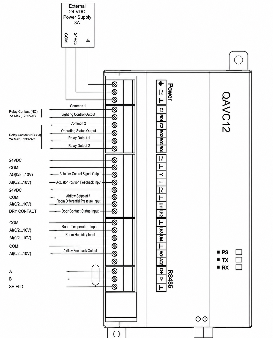
| Interface | Controller / Diagram Function | Project Confirmation |
|---|---|---|
| Power | 24 VDC supply; wiring diagram shows an external 3 A supply | Actual connected load, protection, conductor size, voltage drop and grounding |
| Relay common 1 | Common group associated with lighting control | Current terminal revision, contact type, load and interposing-relay need |
| Relay common 2 | Common group associated with operating/status and relay outputs | Enabled outputs, assignment, contact ratings and controlled equipment |
| Actuator command | 0-10 V analog output to the external actuator | Signal range, direction, common reference, load and loss-of-command state |
| Actuator feedback | Analog input for external-actuator position | Signal range, scaling, direction, endpoint values and loss detection |
| Airflow / pressure demand | Analog input for airflow setpoint or room differential pressure | Selected function, sensor/transmitter range, scaling, units and priority |
| Door contact | Dry-contact input | Normal/open state, debounce, delay, alarm and recovery behavior |
| Temperature input | Room-temperature analog input | Sensor type, range, program use and BMS mapping |
| Humidity input | Room-humidity analog input | Sensor type, range, program use and BMS mapping |
| Airflow feedback | 0-10 V measured-airflow output | Engineering-unit scaling, receiving input and fault value |
| RS-485 | EIA-485 connection with Modbus RTU support | Polarity, shield, topology, termination, address, baud, parity and register map |
| RJ12 panel | Local control-panel connection | Compatible panel, cable, distance, power and whether panel is included |
The wiring diagram identifies one normally open relay group rated 7 A maximum at 230 VAC and another marked 2 A maximum at 230 VAC. Use these values only with the matching approved revision and terminal schedule; do not assign mains loads from the web image alone.
Network and Control-Sequence Setup
For Modbus RTU, document network segment, device address, baud rate, parity, stop bits, register version, read/write permissions and loss-of-communication behavior. Confirm which points are commanded by the BMS and which remain local. If an analog demand and network demand are both wired, define priority and fallback. The local panel should also have an explicit role so that an operator change cannot silently override the engineered sequence.
Before testing, record engineering units, airflow coefficient, pressure-sensor range, analog scaling, actuator endpoints, door state, relay actions, limits, and fail values. Save the approved configuration with the controller revision and valve tag.
Functional Commissioning and Acceptance
Commissioning should begin with point-to-point checks: power, sensor values, door contact, relay actions, panel, network, actuator command, actuator feedback and airflow feedback. Next, command the valve through its range and verify that position and direction match the mechanical drawing. Zero and inspect the pressure path, enter the approved airflow relationship, and compare indicated airflow with an independent field measurement at the defined operating states.
Demonstrate the specified airflow states under representative duct pressure. For room-pressure participation, test closed-door, open-door, recovery, and relevant supply/exhaust combinations. Record alarms, overrides, sensor/network loss, and power recovery. Acceptance is based on measured airflow or room response, not actuator movement, voltage, or communication alone.
How to Select and Specify the Controller
Define the Controlled Variable and Operating States
Begin with the result the branch must maintain: measured airflow, a fixed airflow state, or participation in a room differential-pressure sequence. List normal, unoccupied, minimum, maximum, emergency, door-open, shutdown and recovery states that apply. For each state, identify the demand source, controlled valve, active limits, override priority, alarm condition and required failure response. This prevents the hardware list from being completed before the sequence is understood.
Close the Measurement, Actuator and Interface Schedule
Specify valve mechanism and size, airflow pickup, coefficient or calibration basis, pressure tubing, design airflow states, and available pressure. Then specify the external actuator by motion, torque or thrust, travel, operating time, mounting, command, position feedback, supply, and fail state. Assign only the room pressure, temperature, humidity, door contact, relays, airflow feedback, panel, and Modbus points actually used.
Use a Tag-Level Specification
A useful specification can state: provide a standalone duct airflow and pressure controller with built-in airflow sensing, one project-selected external-actuator command path, actuator-position feedback, the scheduled sensor and door-contact inputs, airflow feedback, local-panel interface where required, and Modbus RTU communication. Configure the controller for the approved valve/pickup relationship, operating states, signal scaling, priority and fail sequence. Submit the controller revision, terminal schedule, point list, actuator compatibility, supplied/by-others scope and commissioning procedure before production.
The mechanical, electrical and controls schedules must describe the same tag. If the actuator or valve is supplied by another party, the controller supplier should return the interface requirements rather than accepting an unnamed “compatible actuator.” If the project changes valve size, pickup, actuator, sensor range, panel, BMS protocol or room sequence, review the tag again before the change is released.
Technical Data, Configuration, And Documentation
Match The Hardware And Wiring Revision
Identify the controller hardware and terminal revision used for each valve tag. Match the product label, wiring drawing, I/O schedule, firmware or program version, local panel, Modbus register map, and external-actuator interface because switching-output groups can vary by revision.
Available Configuration Documents
Configuration documents can include the controller data sheet, current terminal drawing, point list, network requirements, compatible-panel information, external-actuator requirements, valve and pickup drawing, airflow relationship or coefficient source, sensor ranges, cause-and-effect sequence, responsibility schedule, and commissioning method. For custom assemblies, a tag list ties every controller to its valve, actuator, sensors, airflow states, and room-pressure role.
Commissioning and Handover Records
After commissioning, retain the final configuration values, point-to-point results, actuator stroke and feedback checks, airflow or pressure calibration records, tested operating states, alarms, overrides, failure tests, and network settings. Record the drawing and software revisions used during testing so a replacement controller can be configured from the installed record instead of reconstructed from labels or terminal-strip assumptions.
Related Products
When Integrated Actuation Is Preferred
Evaluate the duct airflow controller with integrated fast VAV actuator when the controller, airflow sensing and rotary or linear actuation can be supplied as one compact assembly. It is the closer alternative for new valve packages where its available output, motion and mounting fit the device. The external-actuator controller remains the better candidate when the actuator must be retained, independently specified, remotely mounted or selected outside the integrated range.
When the Control Object Changes
Evaluate the planned VAV airflow and pressure controller when its verified integrated hardware, inputs and application sequence match a broader airflow/pressure task. For direct face-velocity, sash-position or automatic-sash control at a fume hood, use the appropriate fume hood controller. A duct branch application should not be renamed as a fume hood product merely because it serves an exhaust connection.
Valve and Actuator Choices
A VAV butterfly damper provides a rotating-blade mechanism, while a VAV Venturi air valve provides its own flow path and control mechanism. In both cases, approve the valve/pickup data and the external actuator interface together. If measured airflow or pressure logic is unnecessary, review the damper actuator category instead of adding a standalone controller.
Frequently Asked Questions
What is a duct airflow and pressure controller?
A duct airflow and pressure controller is a control device that receives an airflow, pressure, voltage, or network demand and sends a command to a separate actuator. This controller includes differential-pressure airflow sensing and project-configurable analog, digital, panel, and RS-485 interfaces. The delivered control result still depends on the selected valve, airflow pickup, coefficient, pressure tubing, actuator, available pressure, control sequence, field setup, and commissioning.
How does this controller differ from an integrated duct airflow controller?
This product uses a split architecture: the controller and actuator are separate devices connected by wiring. The integrated duct airflow controller combines control, sensing, and a fast rotary or linear actuator in one assembly. Use the split arrangement when the actuator is already specified, must be mounted remotely, needs a different torque or stroke, or cannot be integrated into the controller enclosure.
Is the external actuator included?
The controller page does not imply that every quotation includes an actuator. The required actuator may be selected and supplied with the project or provided by others. Confirm actuator power, command input, position feedback, motion type, torque or thrust, rotation or stroke, action time, fail position, mounting, linkage, environmental rating, and responsibility for installation. The quotation should state the supplied and by-others scope for every valve tag.
Can it control both duct airflow and room differential pressure?
The interfaces support measured airflow control and a room differential-pressure input, but the project sequence determines the active control object and priority. Complete room-pressure control also depends on the room sensor, supply and exhaust arrangement, door events, airflow limits, fan capacity, alarms, and supervisory logic. Connecting a pressure sensor alone does not create a complete room-control system.
Can the controller be used with butterfly dampers and Venturi air valves?
It can be configured for a project using a VAV butterfly damper or a VAV Venturi valve, provided the measurement, actuator, mechanical interface, airflow range, available pressure, and control sequence are compatible. The controller does not turn one valve mechanism into another, and valve-specific pressure behavior, material compatibility, leakage, sizing, and calibration remain part of the valve selection.
Which control and communication interfaces are available?
Available functions include four analog-input roles for room pressure, temperature, humidity, and actuator-position feedback; two 0-10 V output roles for actuator command and airflow feedback; a door-contact input; switching functions; an RJ12 local-panel interface; and EIA-485 communication with Modbus RTU. The approved revision must confirm active channels, scaling, relay assignment, serial settings, register map, and failure behavior.
Why must the wiring drawing be checked against the supplied revision?
Switching-output descriptions and terminal groups can differ by controller revision. The project submittal therefore needs one approved hardware revision, terminal drawing, point list, relay schedule, actuator diagram, and control narrative. Electricians should wire from that approved package rather than from a generic web image or an earlier project drawing.
What information is required for a project-ready quotation?
Provide the application, minimum and maximum airflow, pressure-control requirement, available pressure, valve mechanism and size, airflow pickup and coefficient, tubing arrangement, external actuator data, power, command and feedback signals, room sensors, door input, switching functions, local panel, Modbus requirements, failure sequence, installation conditions, quantity, destination, drawings, and commissioning requirements. XICHENG will use these details to recommend the controller interfaces, define actuator responsibility, and provide the applicable accessories, documentation, testing services, and price.
Contact the Xicheng Engineering Team Today.
Send the airflow and pressure schedule, valve and pickup details, external actuator data, control sequence, I/O and Modbus requirements, terminal or system drawings, and commissioning requirements. XICHENG will recommend a controller configuration and provide the interface details, responsibility schedule, applicable accessories, and professional quotation within 24 hours.
Shenzhen Office: No. 34 Zhenxing Road (Shengtaian Heavy Industrial Park B), Loucun, Guangming New Dist, Shenzhen, Guangdong, China
WhatsApp: +86 181 2647 8161
Engineering Mailbox: fanalax34@gmail.com