


Description
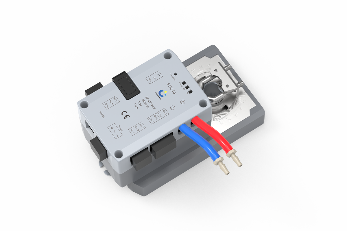
This fume hood controller combines VAV airflow-control logic with a matched rotary or linear actuator for variable-volume fume hood exhaust. It can respond to face-velocity or sash-position input, use built-in differential-pressure airflow sensing, and command a compatible butterfly damper or Venturi air valve. Within XICHENG’s laboratory airflow controls and actuators range, it serves the hood-level exhaust loop rather than general HVAC zone control.
- Integrated rotary or linear controller-and-actuator configurations for the selected fume hood valve mechanism
- Applicable to project-configured butterfly damper or Venturi air valve systems serving fume hood exhaust
- AC/DC 24 V power with DC 2-10 V or 4-20 mA control and airflow feedback
- RS-485 Modbus RTU communication plus switch-control interfaces
- Energy-saving mode, one-button emergency exhaust, and audible/visual alarm functions
Each fume hood VAV controller is configured to order. Define the hood and sash arrangement, target face velocity, minimum through emergency airflow states, sensing method, valve mechanism, actuator motion, command and feedback signals, alarm sequence, BMS interface, supplied components, and commissioning method before production.
Product Overview
Where The Integrated Fume Hood Controller Fits
Use the integrated package where a fume hood controller must interpret sash or face-velocity demand and move the connected exhaust-airflow device. Demand can follow a sash-position signal, direct face-velocity feedback, or a defined control sequence using the built-in differential-pressure/flow sensing circuit. The controller can be paired with different valve mechanisms, but valve airflow capacity, pressure behavior, material, and size remain properties of the selected butterfly damper or Venturi air valve.
How It Fits Into The Airflow-Control Loop
The selected hood input represents the required exhaust response. The controller processes that input, drives the integrated actuator, and changes the connected airflow-control device. Analog signals, switch functions, and RS-485 Modbus RTU can connect the controller to sash or face-velocity sensing, local controls, and the BMS. Actual exhaust airflow and face velocity still depend on the hood opening, valve selection, available pressure, duct and fan capability, sensor arrangement, control sequence, and field commissioning.
Product And System Boundary
The integrated fume hood controller supplies the VAV control and actuator functions; it does not generate airflow or replace the hood, sash, valve body, fan, duct design, power distribution, field wiring, balancing, BMS programming, containment testing, or final face-velocity verification. Depending on the project, the valve, sensor, display panel, fan or VFD, and installation hardware may be supplied separately. Select the package only after these interfaces and responsibilities are clear.
Product Selection Summary
Choose This Controller When
This fume hood controller is a good fit when a variable-volume hood exhaust system needs one coordinated controller-and-actuator package matched to the hood input, exhaust valve mechanism, and project sequence.
- Exhaust demand is based on face velocity, sash position, differential-pressure/flow sensing, or a defined combination of these inputs.
- The selected fume hood butterfly damper or Venturi air valve can be matched to a rotary or linear actuator configuration.
- The electrical design can support 24 V power, the required analog signals, switch functions, and RS-485 Modbus RTU.
- The project will verify actual hood airflow, face velocity, alarms, emergency exhaust, feedback, and BMS points during commissioning.
Check These Conditions Before Selection
Confirm the sash geometry, target face velocity, airflow states, valve shaft or stroke, torque or thrust, sensor range, failure position, response time, mounting clearance, panel interface, terminal assignment, Modbus requirements, and alarm sequence for the selected hood. A communication protocol or model name alone does not establish mechanical compatibility, hood safety behavior, or airflow performance.
Information Needed To Configure The Controller
Provide the hood type and quantity, sash arrangement and travel, target face velocity, minimum, normal, maximum and emergency airflow, sensing method, valve type and size, actuator interface, available pressure, power, command and feedback signals, alarm and failure sequence, BMS requirements, and installation drawings. XICHENG can then recommend the fume hood controller, integrated actuator, interfaces, included components, and configuration values that need to be confirmed before production.
Key Specifications
Controller And Interface Data
Use the specifications below to compare the fume hood controller, sensing method, actuator, and exhaust-valve interface. The selected combination follows the hood control tag and defined operating sequence rather than including every available signal, sensor, and actuator option in one assembly.
| Item | Specification |
|---|---|
| Model / SKU | FHC10 |
| Product type | Fume hood VAV controller with integrated rotary or linear actuator configuration |
| Primary application | Variable-air-volume control for fume hood exhaust |
| Supported airflow-control devices | Project-configured butterfly damper or Venturi air valve serving fume hood exhaust |
| Primary control function | Fume hood airflow control using the selected sash-position, face-velocity, or differential-pressure/flow input |
| Sensor input | One 0-10 kΩ or 2-10 V analog input for a fume hood sash-position sensor or face-velocity sensor |
| Built-in sensing | Differential-pressure / flow sensing; final range and performance require project confirmation |
| Pressure setup | Configurable differential-pressure coefficient |
| Power supply | 24 VDC ±10%, 20 W maximum; or 24 VAC ±10%, 40 VA maximum |
| Control signal | DC 2-10 V or 4-20 mA; select the required signal convention for the project |
| Airflow feedback | One 0-10 V or 0-20 mA analog output; define the final scaling in the project control schedule |
| Communication | RS-485 with Modbus RTU support |
| Digital I/O | One personnel-detection input plus operating-status and lighting-control relay outputs |
| Operating functions | Energy-saving mode and one-button emergency exhaust |
| Alarm | Audible and visual alarm; thresholds and sequence are project-defined |
| Actuator configurations | Integrated rotary or linear actuator options |
| Travel adaptation | Button-based automatic adjustment of travel start and end positions |
| Operating environment | 0 to +50°C; 10-95% RH, non-condensing |
| Storage environment | -20 to +50°C; 10-95% RH, non-condensing |
| Final product definition | Quotation, final technical schedule, dimensional drawing, wiring information, and defined control sequence |
Model, Output, And Dimension Comparison
| Model | Motion | Output | Operating Time / Travel | Overall Dimensions | Shaft Diameter |
|---|---|---|---|---|---|
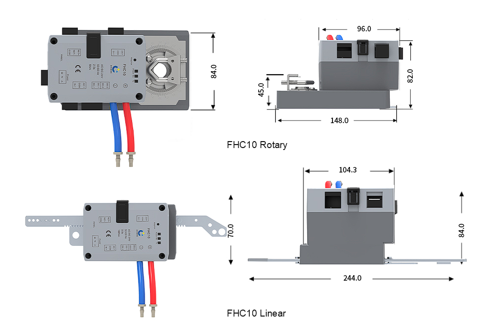
| FHC10-5 | Rotary | 5 N·m | 2.0 s / 0-90° | 148 × 84 × 82 mm | 15.5 mm |
| FHC10-15 | Rotary | 15 N·m | 5.0 s / 0-90° | 165 × 84 × 85 mm | 19.5 mm |
| FHC10-30 | Rotary | 30 N·m | 9.0 s / 0-90° | 165 × 84 × 85 mm | 19.5 mm |
| FHC10-L | Linear | 100 N | 3.0 s / 0-100 mm | 244 × 70 × 84 mm | Not applicable |
Use the model table to compare motion type, output, response, travel, and installation envelope. Final selection also requires the fume hood exhaust valve’s torque or thrust demand, mechanical interface, operating pressure, movement direction, fail requirement, and available installation clearance.
Sensor range and accuracy, ingress protection, complete terminal assignments, communication registers, panel compatibility, fail action, and the BMS point list depend on the selected project configuration. Confirm these fields together with the mounting arrangement and supplied accessories before manufacture or installation.
Control Inputs And Operating Functions
Face-Velocity Control
The fume hood controller can use face-velocity input to command the matched actuator and exhaust-airflow device as the sash opening or operating state changes. Required face velocity, sensing location, allowable deviation, response, alarm threshold, and acceptance method remain project values rather than universal product specifications. The hood, fan, duct and valve must also provide the required airflow and available pressure. Evaluate the controller together with the face-velocity sensor, valve authority, exhaust-system capability and commissioning method rather than treating actuator position as proof of containment.
Sash Position And Differential-Pressure/Flow Inputs
The controller supports sash-position input and includes differential-pressure/flow sensing. In position-sensor control mode, it combines sash-opening information with the selected face-velocity requirement to calculate exhaust demand, adjusts the connected VAV device, and uses measured airflow with the opening area to calculate average face velocity. In face-velocity-sensor control mode, the sensor signal drives valve adjustment to maintain the selected hood face velocity. The project must define the primary input, scaling, alarm and failure behavior, and commissioning method. The built-in pressure-based airflow sensing does not make this product a room differential-pressure controller.
Setup Controls And Airflow Sensor Connections
| Component | Function | Installation Note |
|---|---|---|
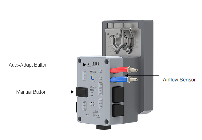
| Auto-Adapt Button | Used to enter the controller’s adaptation or manual/automatic setup workflow. | Run only after the actuator and controlled mechanism have been mechanically checked. |
| Manual Button | Press-and-rotate adjustment for the connected U-shaped regulating-valve position. | Use for setup and movement checks under the defined commissioning procedure. |
| Airflow Sensor + Port | Inlet connection for the airflow-sensing circuit. | Connect to the positive/inlet pressure point shown on the project tubing diagram. |
| Airflow Sensor – Port | Outlet connection for the airflow-sensing circuit. | Connect to the designated negative/outlet pressure point and check tubing polarity before calibration. |
Before setup, confirm pressure-tube routing, hood sensor scaling, actuator travel limits, sash operating range, and the permitted manual-operation procedure for the supplied controller-and-valve assembly. Reversed sensor tubing or an unchecked mechanical travel range can produce an incorrect airflow indication or drive the connected mechanism in the wrong direction.
Emergency Exhaust, Airflow Alarm, And Energy-Saving Functions
The fume hood controller provides one-button emergency exhaust, audible and visual alarm capability, and an energy-saving mode. Define their triggers and outputs in the hood control sequence. For each alarm, specify the monitored variable, threshold, delay, reset method, local indication, remote reporting, and required valve or fan action. Emergency exhaust needs a defined airflow state and interlocks, while energy-saving operation needs a defined sash or occupancy condition and minimum safe airflow. During commissioning, verify actuator movement, feedback, hood airflow or face-velocity response, local indication, and BMS status without assuming that displayed actuator position alone proves performance.
Integrated Actuator Options
The integrated fume hood controller is available with rotary or linear actuator motion. Selection follows the mechanical movement of the butterfly damper, Venturi air valve, or linkage used to regulate hood exhaust. Use the model table in Key Specifications for output, operating time, travel, dimensions, and shaft diameter; then confirm those values against the actual controlled device and required hood response.
Rotary Actuator Configuration
Rotary Motion And Available Models
The 5, 15, and 30 N·m rotary configurations drive fume hood exhaust devices through angular rotation. They provide different output and operating-time options within a 90-degree travel range. Choose among them from the valve load and required control response, not simply from duct diameter or the highest available torque.
Rotary Selection Checks
Confirm the valve shaft diameter and geometry, required torque at the project pressure condition, usable blade or mechanism travel, opening direction, response requirement, fail position, mounting orientation, and wiring clearance. Also check whether a bracket, coupler, travel stop, or other mounting hardware is required. The actuator must reach the intended operating range without forcing the valve beyond its mechanical limits.
Linear Actuator Configuration
Linear Motion And Available Model
The 100 N linear configuration is intended for a fume hood exhaust mechanism that requires straight-line movement. Its thrust and travel must be matched to the connected linkage rather than treated as interchangeable with a rotary actuator. The full stroke is useful only when the valve or mechanism can use that movement safely and repeatably.
Linear Selection Checks
Confirm the required stroke, operating load, connection points, motion direction, end positions, mounting length, and surrounding clearance. Check the linkage geometry through the entire movement range and identify every included lever, bracket, or adapter. The installation should not transfer side load or misalignment into the actuator rod.
How To Choose Between Rotary And Linear Motion
Select rotary motion for a compatible rotating shaft or blade and linear motion for a translating mechanism. If the device drawing does not establish the shaft or stroke interface, required output, travel, direction, and mounting space, actuator selection is not complete. Each quotation should identify the selected model, controlled device, mechanical interface, power, signal arrangement, supplied mounting parts, and commissioning requirements.
Valve And System Compatibility
Butterfly damper Integration
With a butterfly damper, the fume hood controller drives the rotating blade used to regulate hood exhaust airflow. The damper body, blade, shaft, seals, material, size, airflow range, and pressure condition remain separate damper specifications. Compatibility depends on the actual shaft interface, required torque and angle, opening direction, mounting space, signal arrangement, and response required by the hood control sequence.
Venturi Air Valve Integration
With a Venturi air valve, the controller and actuator respond to fume hood airflow demand while the selected valve provides its own flow, pressure, material, size, and mechanical characteristics. Confirm the valve motion interface, required travel or output, hood airflow schedule, available pressure, sensing method, and fail behavior. The controller name does not establish pressure-independent valve performance.
Controller Scope Versus A Complete Control Package
This fume hood controller and actuator is not a complete fume hood ventilation system by itself. A project may also require the hood and sash, exhaust valve, sash-position or face-velocity sensor, pressure/flow tubing, display panel, fan or VFD, power, wiring, BMS programming, balancing, containment testing, and final face-velocity verification. Mark each item as supplied, optional, by others, or pending selection.
For a fume hood retrofit, also document the existing hood and sash geometry, exhaust valve, airflow states, face-velocity requirement, actuator removal space, shaft or linkage condition, reusable wiring, sensor tubing, alarm devices, and BMS point compatibility. Do not reuse existing hardware only because its voltage or nominal shaft size appears similar.
Applications And Project Fit
Variable-Air-Volume Fume Hood Exhaust
The fume hood controller is intended for hood exhaust systems in which airflow demand changes with sash position, measured face velocity, operating mode, or a defined combination of these inputs. It can support new installations and retrofits when the hood opening, airflow states, sensing method, exhaust valve, actuator mechanics, fan or VFD coordination, alarm sequence, and acceptance method are defined. The controller regulates the selected device but does not create exhaust capacity or correct an undersized duct and fan system.
Face-Velocity And Sash-Based Control
For direct face-velocity control, locate and scale the sensor so its signal represents the hood condition used by the defined sequence. For sash-based control, define how opening area maps to airflow demand and how measured airflow is used for indication or correction. Both strategies require the target face velocity, minimum and emergency airflow, sash arrangement, sensor location, alarm response, valve authority, fan response, and final field verification. The controller supports the airflow loop but does not replace hood containment testing.
When This Product Is Not The Right Controller
Do not select this product for room differential-pressure control, general supply-air terminal control, or stand-alone fan control merely because it has pressure sensing, analog I/O, and Modbus communication. It also does not replace a sash-drive controller when the main task is automatic window movement and anti-pinch safety. Those applications require products whose primary control task and I/O are documented for that purpose.
When Another Controller Should Be Evaluated
Choose the Fume Hood Face Velocity Controller (FHC11) when direct face-velocity feedback defines the control loop. Use the Sash-Position Fume Hood Controller (FHC11-S) when resistive sash-position input defines demand. Select the Split-Type Fume Hood VAV Controller (FHC12) when a separate controller must command one or more external actuators. For automatic sash operation combined with VAV airflow control, evaluate the Automatic Sash Fume Hood Controller (FHC100); for sash motion and safety control without complete VAV airflow control, use the Automatic Fume Hood Sash Controller (FSC10). Compare these products by hood input, integrated or split architecture, actuator motion, I/O, sash-control scope, and supplied components.
Installation, Wiring, And Commissioning
Mechanical And Electrical Checks Before Installation
Begin installation after matching the fume hood controller and actuator to the selected exhaust-airflow device and hood sequence. For a rotary arrangement, verify shaft diameter and geometry, actuator output, 90-degree travel requirement, movement direction, mounting orientation, linkage, and surrounding clearance. For a linear arrangement, verify the required stroke, thrust, connection points, movement direction, end positions, and available installation length. Confirm AC/DC 24 V power, protection and isolation, the selected DC 2-10 V or 4-20 mA command, DC 2-10 V feedback, sash or face-velocity sensor connection, switch-control requirements, RS-485 wiring, panel connection, cable routing, and grounding. Follow the final hood schedule, control sequence, drawing, and wiring information rather than a generic family diagram.
Wiring Terminal Reference
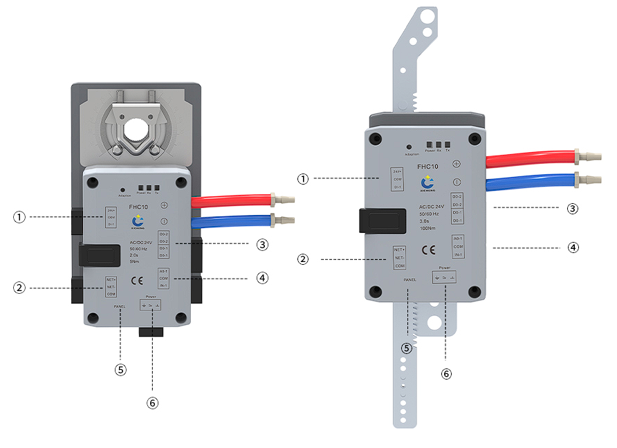
The terminal layout below helps coordinate power, hood sensor, relay, panel, and RS-485 connections for the rotary and linear fume hood controller configurations. Before field wiring begins, match every terminal to the diagram supplied for the selected unit because sensor type, relay use, panel connection, and power arrangement can vary by project.
| Callout | Interface | Terminals | Function |
|---|---|---|---|
| 1 | Digital input | 24Vdc, COM, DI-1 | 24 V output, common, and personnel-detection input |
| 2 | RS-485 communication | NET+, NET-, COM | RS485+, RS485-, and communication common |
| 3 | Digital outputs | RO-1 pair, RO-2 pair | Operating-status output and lighting-control output |
| 4 | Analog signal terminals | AO-1, COM, IN-1 | 0-10 V or 0-20 mA airflow feedback, common, and 0-10 kΩ or 2-10 V position/face-velocity sensor input |
| 5 | Operator panel | Panel | RJ12 operator-panel connection |
| 6 | Power | Protective earth, 24Vdc, COM | Protective earth, 24 V supply, and supply common |
Control And Communication Coordination
The controller supports RS-485 and Modbus RTU. Define the address, baud rate, register map, terminal schedule, and BMS point list before integration begins. Confirm sash or face-velocity signal scaling, analog common/reference, command and feedback direction, shielding and grounding, alarm and emergency contacts, restart behavior, loss-of-signal action, manual override, and responsibility for panel programming and BMS graphics. A point-to-point check must verify every input and output against the defined fume hood sequence; successful communication alone does not demonstrate correct valve movement, hood airflow, or face-velocity response.
Adaptation, Functional Testing, And Acceptance
Use the button-based travel adaptation function to establish the actuator’s start and end positions for the selected mechanism. After adaptation, verify movement direction, full usable travel, mechanical freedom, command and feedback relationship, normal control response, energy-saving mode, one-button emergency exhaust, audible and visual alarms, switch inputs, panel indication, and the required Modbus/BMS points. Final testing measures actual airflow or face velocity under the defined hood and sash conditions and confirms the response to changes in sash position, operating mode, alarm state, and emergency command. Record the controller configuration, actuator selection, signal scaling, setpoints, alarm thresholds, test conditions, and results so later service work is based on measured performance rather than actuator position alone.
How To Select And Specify The Controller
Define The Control Objective First
Write the required fume hood behavior before selecting the controller hardware. Identify the hood and sash type, target face velocity, minimum, normal, maximum and emergency exhaust airflow, occupied or energy-saving states, emergency command, alarm conditions, and expected valve and fan response. Then define whether demand comes from sash-position mapping, direct face velocity, differential-pressure/flow sensing, or a defined combination. This step determines what the controller must receive and what the exhaust valve, fan or VFD, local panel, and BMS must do.
Match The Controller To The Valve And Actuator Interface
After the hood control objective is defined, select the butterfly damper or Venturi air valve and document its mechanical and airflow requirements. For rotary motion, state the shaft diameter, required torque, angle, direction, response, failure position, and mounting limits. For linear motion, state the stroke, thrust, connection geometry, direction, response, and available installation space. Add the required AC/DC 24 V supply, command and feedback convention, sash or face-velocity sensor arrangement, switch interfaces, panel connection, and RS-485/Modbus requirements. Link the controller configuration to these fields so any change in hood, valve, shaft, stroke, sensing method, or sequence is reflected in the final model, drawings, and settings.
Confirm The Project Control Sequence
The final specification describes hood startup, sash movement, normal and reduced-airflow operation, emergency exhaust, alarm indication, local override, signal loss, power loss, restart, failure behavior, BMS commands and feedback, and acceptance testing. Allocate responsibility for the controller, actuator, valve, sash and face-velocity sensors, panel, fan or VFD, power, field wiring, network programming, airflow balancing, containment testing, and face-velocity verification. The final hood schedule, drawing, wiring information, and sequence then guide manufacture, installation, commissioning, and maintenance.
Technical Data, Configuration, And Documentation
Data Needed For The Final Controller Configuration
Use the specification and model tables on this page for initial comparison, then confirm the exact configuration for each fume hood control tag. The final selection identifies the hood and sash arrangement, airflow states, target face velocity, actuator model, sensor type and range, signal scaling, enclosure requirements, mounting bracket or linkage, terminal allocation, communication settings, operator-panel compatibility, alarm thresholds, failure action, and accessories. Also check that the installation location provides suitable temperature, humidity, wiring access, tubing route, and mechanical clearance. For chemical exhaust, confirm the controller location and the compatibility of the valve, tubing, sensor connections, and exposed components with the actual air stream.
Before installation, assign responsibility for calibration data, network addresses, alarm values, point-to-point checks, and final airflow or face-velocity testing. Recording these responsibilities with the hood tag prevents field setup from depending on assumptions made from a general product description.
Available Configuration And Handover Documents
Available documents can identify the hood control tag, controller and actuator model, exhaust valve, mechanical interface, applicable output and operating time, power, command and feedback convention, sash or face-velocity sensing method, relay functions, panel connection, RS-485/Modbus interfaces, alarms, emergency behavior, failure sequence, and included components. Depending on the order, XICHENG can also provide the applicable product data sheet, mounting drawing, wiring diagram, hood and valve schedule, point list, control sequence, and commissioning record.
Keep the configuration documents aligned with the sash schedule, target face velocity, airflow states, alarm limits, and emergency-exhaust sequence. If the hood, valve, actuator interface, sensor, signal convention, or operating sequence changes, update the affected drawing, settings, and test requirements before installation.
Related Products
Related Airflow-Control Devices
The fume hood controller must be selected with an exhaust-airflow device that matches the hood’s mechanical and performance requirements. The VAV Butterfly damper is relevant when the hood exhaust uses a rotating blade and the controller/actuator can be matched to its shaft, torque, angle, mounting, and airflow schedule. The VAV Venturi Air Valve should be evaluated when the specification calls for a Venturi mechanism and its corresponding size, airflow, pressure, material, and actuator arrangement. These products are selected separately; neither valve body is automatically included with the controller.
Related VAV Controls And Application Accessories
Another fume hood controller may be more appropriate when the application centers on direct face-velocity feedback, sash-position demand, a split controller with external actuators, or automatic sash operation. Browse the Variable Air Volume Controls & Actuators category for the available control architectures. For separate hood sensors, panels, sash drives, and safety components, see Fume Hood System Accessories. Choose related products by control input, actuator arrangement, sash-control functions, and included components rather than model-name similarity.
Frequently Asked Questions
What does this fume hood controller control?
The fume hood controller receives the selected sash-position or face-velocity demand and commands its matched rotary or linear actuator so a butterfly damper or Venturi air valve can change hood exhaust airflow. Built-in differential-pressure/flow sensing supports the airflow-control loop, while emergency exhaust, alarm, and energy-saving functions follow the defined sequence. The product does not create airflow, so the hood, fan, ductwork, valve, available pressure, sensor arrangement, balancing, and final face-velocity test must support the required result.
Is the fume hood controller a complete butterfly damper or Venturi air valve?
No. It is a configurable controller-and-actuator product family. It can be matched to a butterfly damper or Venturi air valve system, but the valve body, size, material, connection, airflow range, pressure condition, and valve-specific performance must be selected separately unless the quotation explicitly includes them. The technical schedule should identify every supplied and excluded component.
Can the fume hood controller be used with both butterfly and Venturi airflow-control devices?
Yes. This fume hood VAV controller can be configured for a compatible butterfly damper or Venturi air valve serving hood exhaust. A butterfly arrangement requires matching the rotary shaft, torque, angle, direction, travel time, and mounting. A Venturi arrangement requires matching the valve’s mechanical interface, travel or output requirement, hood airflow schedule, pressure condition, and control package. Determine compatibility from the selected valve and actuator documents rather than from the controller name alone.
What power, control, feedback, and communication interfaces are available?
Available interfaces include AC/DC 24 V power, DC 2-10 V or 4-20 mA control, DC 2-10 V feedback, a reserved switch-control interface, and RS-485 with Modbus RTU support. Define the selected signal convention, terminal assignments, switch-point quantity and rating, address, baud rate, register map, grounding, and BMS point list for the quoted configuration.
How are the rotary and linear actuator configurations selected?
Select the actuator from the controlled device’s mechanical movement. The rotary option is evaluated from shaft size, required torque, 90-degree travel, direction, response, and mounting. The linear option is evaluated from required stroke, thrust, connection geometry, direction, and available space; the available linear configuration has 100 N thrust and up to 100 mm travel. Use the final valve drawing to define the interface.
Does the controller include a display panel, valve body, sensors, or BMS programming?
Not automatically. The controller includes differential-pressure/flow sensing capability and supports sash-position or face-velocity input, but the supplied hood sensor, display panel, valve body, fan or VFD, power components, field wiring, network work, and BMS programming depend on the quotation. Mark each item as included, optional, by others, or pending selection before order approval.
What information is required for a project-ready quotation?
Provide the fume hood control tags and quantities, hood and sash arrangement, target face velocity, minimum/normal/maximum/emergency airflow, selected butterfly or Venturi device, valve size and pressure condition, actuator shaft or stroke interface, sensing method, mounting constraints, AC/DC 24 V availability, signals, panel and Modbus/BMS requirements, alarm and failure sequence, drawings, destination, and documentation requirements.
Contact the Xicheng Engineering Team Today.
Send the fume hood and sash schedule, target face velocity, minimum, normal, maximum and emergency exhaust airflow, selected butterfly damper or Venturi air valve, actuator interface, sensing strategy, available pressure, power and signals, panel and BMS requirements, alarm and failure sequence, drawings, quantity, and destination. XICHENG will recommend a fume hood controller and integrated actuator configuration and provide the applicable specifications, included components, interface details, documentation, and commercial pricing.
🎯 Shenzhen Office: No. 34 Zhenxing Road (Shengtaian Heavy Industrial Park B), Loucun, Guangming New District, Shenzhen, Guangdong, China
☎️ WhatsApp: +86 181 2647 8161
📬 Engineering Mailbox: fanalax34@gmail.com