


Description
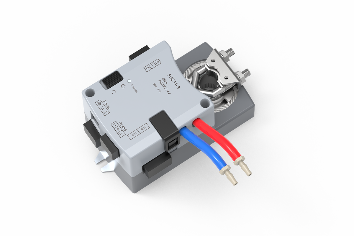
This fume hood controller converts sash position and the configured face-velocity requirement into an exhaust-airflow demand, then corrects the connected butterfly damper against measured airflow. It is the position-based option in XICHENG’s laboratory airflow controls and actuators range; it does not replace direct face-velocity monitoring when that variable is required for acceptance.
- Position demand from one polarity-independent resistive sash sensor input
- Closed-loop correction through the airflow-feedback interface and positive/negative pressure connections
- Integrated 3S4N rotary actuator with approximately 3-second operation and 4 N·m output
- 24 V AC/DC supply, two project-assigned RO outputs, and an RJ12 local-panel interface
- RS-485 Modbus RTU communication, energy-saving operation, and low-condition alarm support
Every controller is configured to order. Define the fume hood and sash geometry, sensor travel, target face velocity, minimum through emergency airflow states, butterfly-damper shaft and torque, airflow pickup, panel and output functions, Modbus scope, alarm and failure sequence, supplied components, and commissioning method before production.
Product Overview
Where the Integrated Fume Hood Sash Position Controller Fits
Use this controller where the required fume hood exhaust volume is intended to follow sash opening and the project also requires measured-airflow correction. A resistive position sensor represents sash travel. The controller combines that signal with the approved face-velocity objective, calculates the required exhaust volume, and commands its integrated rotary actuator. The confirmed application is a compatible fume hood butterfly damper; the damper size, airflow range, pressure condition, material, and chemical compatibility remain separate project selections.
How It Fits into the Airflow-Control Loop
Sash movement supplies an early demand change before the exhaust branch reaches a new steady state. The controller moves the damper from that position-based demand, while the differential-pressure connections and airflow-feedback interface provide the measured result used for correction. The loop therefore depends on both the position signal and a valid airflow relationship. Actual face velocity still depends on clear opening area, hood geometry, available pressure, fan and duct capability, damper authority, pickup installation, signal scaling, and field calibration.
Product and System Boundary
The supplied product combines the controller and approximately 3-second, 4 N·m rotary actuator. It does not automatically include the sash-position sensor, butterfly-damper body, airflow pickup, pressure tubing, local panel, fan or VFD, power components, field wiring, network programming, balancing, or face-velocity acceptance testing. The quotation and technical schedule must identify each included, optional, and by-others item so the controller is not mistaken for a complete hood airflow-control package.
Product Selection Summary
Choose This Controller When
This sash position fume hood controller is a good fit when a variable-volume hood needs an integrated controller and rotary actuator, sash opening is the principal demand input, and actual exhaust airflow is available to close the control loop.
- The hood uses one position signal that can represent its usable sash travel and opening relationship.
- The selected butterfly damper can be matched to approximately 4 N·m rotary output and the available mounting envelope.
- The control design provides 24 V AC/DC power and defines the two RO outputs, RJ12 panel interface, and RS-485 Modbus RTU scope.
- The project will calibrate position, airflow feedback, damper direction, face velocity, alarms, operating states, and BMS points on site.
Conditions That Require Project Review
Review is required when horizontal, combination, or multiple sashes cannot be represented by one resistive input; when the damper needs more torque, linear motion, spring return, a nominated actuator, or remote controller mounting; or when pickup placement, available pressure, fan behavior, panel functions, output ratings, communication settings, alarm sequence, and failure response affect selection. A model name or nominal actuator output alone cannot establish airflow performance or mechanical compatibility.
Information Needed To Configure the Product
Provide the hood type and quantity, sash arrangement, clear width and travel, bypass geometry, target face velocity, minimum/normal/maximum/energy-saving/emergency airflow, position-sensor details, damper size and shaft, required rotation and torque, available pressure, airflow pickup and tubing arrangement, fan control, 24 V supply, RO assignments, panel, Modbus requirements, alarm and failure sequence, drawings, quantity, and destination. XICHENG can return a proposed controller configuration, documented interfaces, supplied-scope details, required project confirmations, and commercial pricing.
Key Specifications
Controller and Interface Data
Use the data below to compare the controller, sash sensor, integrated actuator, local interface, and BMS connection. The final assembly is configured for one approved hood control tag; a listed interface or function does not mean that every sensor, panel, damper, cable, and field service is included automatically.
| Item | Specification |
|---|---|
| Model / SKU | FHC11-S |
| Product type | Sash-position fume hood VAV controller with integrated rotary actuator |
| Primary application | Position-demand airflow control for laboratory fume hood exhaust |
| Controlled device | Project-matched butterfly damper; valve body selected separately unless included in the quotation |
| Sash-position input | One polarity-independent resistive analog input |
| Airflow feedback | Actual-airflow feedback interface with positive and negative differential-pressure connections |
| Control method | Sash-position demand with actual-airflow correction for the configured face-velocity objective |
| Integrated actuator | 3S4N fast rotary configuration; approximately 3 seconds and 4 N·m |
| Power supply | 24 V AC/DC; revision-specific supply capacity and consumption require confirmation |
| Relay outputs | Two RO outputs for project-assigned operating, interlock, alarm, or lighting functions |
| Local panel | Independent RJ12 communication interface |
| BMS communication | RS-485 with Modbus RTU support |
| Operating functions | Energy-saving mode and low-face-velocity alarm support under the approved sequence |
| Setup features | Visible adaptation control, manual control, and forward/reverse switch |
| Operating environment | 0 to +50°C; 10-95% RH, non-condensing |
| Storage environment | -20 to +50°C; 10-95% RH, non-condensing |
| Final product definition | Quotation, approved controller revision, wiring diagram, control sequence, and project technical schedule |
Dimensions and Installation Envelope
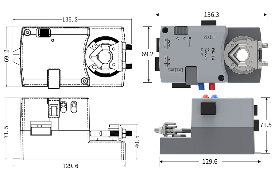
| View | Dimension | Value | Selection Use |
|---|---|---|---|
| Top | Overall length | 136.3 mm | Check space around the damper shaft |
| Top | Body width | 69.2 mm | Check adjacent duct and bracket clearance |
| Side | Base length | 129.6 mm | Coordinate mounting footprint and access |
| Side | Overall height | 71.5 mm | Check projection from the mounting plane |
| Side | Local shaft-related dimension | 40.5 mm | Read with the drawing; not an overall size |
Use the drawing and table to check the controller body, actuator interface, electrical connectors, pressure tubes, manual controls, and future service access. Final mechanical approval still requires the damper shaft profile, coupling, required rotation, blade torque at the operating pressure, stops, bracket geometry, and installation orientation.
Power documentation must also be resolved for the supplied revision. The manual lists 24 VDC ±10% at 10 W maximum and 24 VAC ±10% at 20 VA maximum, while the visible nameplate shows 9 VA and 5 W. These values remain separate documentation contexts; the approved submittal must state the applicable supply capacity, protection, conductor sizing, and wiring data. Sensor range and accuracy, pressure range, ingress protection, relay rating, Modbus registers, and universal response performance are not published as confirmed specifications.
Control Inputs and Operating Functions
Sash Position as the Demand Signal
The controller uses one resistive position input to represent sash travel. During configuration, the closed position, normal working height, maximum approved opening, and any intermediate control points are related to the hood’s effective open area. The controller combines that position information with the selected face-velocity objective to calculate exhaust demand. The relationship is specific to the hood geometry: identical sash heights do not guarantee identical open area, bypass behavior, leakage, or required airflow.
Actual-Airflow Feedback and Face-Velocity Control
Position supplies the initial demand, but the same damper angle can produce different airflow as duct pressure, fan operation, and system resistance change. The positive and negative pressure connections and actual-airflow feedback interface allow the controller to correct its command against the measured exhaust condition. This feedback supports the configured face-velocity objective without claiming that the controller directly measures velocity at the sash opening. Final face velocity must be tested at the hood under the actual room and exhaust conditions.
Setup Controls and Airflow-Feedback Interfaces
| Component | Confirmed Function | Project Check |
|---|---|---|
| Resistive position input | Receives one polarity-independent sash-position signal | Verify sensor characteristic, useful travel, zero, full scale, direction, and repeatability |
| Positive / negative pressure ports | Connect the differential-pressure airflow-feedback arrangement | Verify pickup location, tubing polarity, leaks, zero, scaling, and calibration relationship |
| Adaptation control | Supports the supplied controller’s setup workflow | Use only after shaft, coupling, direction, stops, and free movement are checked |
| Manual and direction controls | Support movement and direction checks during setup | Follow the approved revision instructions and prevent travel beyond mechanical limits |
Before setup, verify that the sash sensor travels smoothly through the complete usable opening and that the pressure tubes are short, supported, unobstructed, and connected to the correct pickup points. The airflow relationship must be established for the selected damper and duct arrangement. A reversed tube, unstable position signal, incorrect shaft direction, or unverified travel limit can produce a plausible controller value while the actual hood airflow moves in the wrong direction.
Energy-Saving, Alarm, and Output Functions
The product supports energy-saving operation, a low-face-velocity warning sequence, two project-assigned RO outputs, an RJ12 local-panel interface, and RS-485 Modbus RTU. Their behavior is defined by the project rather than by the model name. Specify the operating state that activates reduced airflow, the minimum permitted exhaust condition, alarm threshold and delay, local indication, acknowledgement and reset, emergency or override response, relay assignments, BMS reporting, communication-loss behavior, and restart state. Commissioning must verify the complete sequence instead of assuming that enabled functions are correctly assigned.
Integrated Actuator Configuration
The sash-position controller uses one integrated fast rotary actuator architecture for a compatible butterfly damper. The 3S4N configuration must be assessed against the actual valve and installation because its speed and output describe the actuator, not the airflow performance of the complete hood system. Projects that require linear motion or another actuator architecture should use a controller designed for an external or differently integrated actuator.
Fast Rotary Motion and Available Output
The integrated actuator is identified as an approximately 3-second, 4 N·m rotary configuration. Its role is to convert the controller command into angular movement at the damper shaft after sash position changes. Rapid movement supports the early demand response, while the airflow-feedback loop corrects the final output. The published operating time is not a universal system-response guarantee because the sensor, controller tuning, damper, fan, duct pressure, and hood volume also affect recovery.
Rotary Mechanical Selection Checks
Confirm the damper shaft diameter and profile, coupling engagement, required angle, opening direction, blade torque at the project pressure, usable mechanical stops, bracket geometry, installation orientation, cable and tubing clearance, and service access. The actuator should move through the required control range without forcing the blade beyond its limits or operating continuously at a position with inadequate control authority. Chemical exhaust also requires a separate compatibility review of the damper body, blade, shaft, seals, fasteners, pickups, and tubing.
When the Integrated Architecture Should Not Be Used
Select another arrangement if the damper requires greater output, linear motion, mechanical spring return, a certified failure position, a nominated actuator brand, remote controller mounting, or an interface that the integrated housing cannot accept. A split fume hood controller can then command an external actuator chosen for the valve. The quotation should identify the controller, actuator, damper, adapter or bracket, movement, fail behavior, supplied wiring, and commissioning responsibility so the substitution remains technically controlled.
Valve and System Compatibility
Butterfly damper Integration
The intended controlled device is a fume hood exhaust butterfly damper with a shaft and load compatible with the integrated rotary actuator. The damper body, blade, shaft, seals, material, size, connection, airflow range, pressure condition, leakage behavior, and chemical-exposure boundary remain damper specifications. Match the actuator interface, blade angle, opening direction, torque demand, pressure load, and mounting space to the selected damper rather than choosing from duct diameter alone.
Airflow Pickup, Fan, and Duct Coordination
The feedback loop requires an airflow pickup and pressure relationship that represent the installed branch. Confirm pickup orientation, required straight duct, tubing route, available pressure, fan or VFD sequence, minimum stable airflow, and damper authority through the normal operating range. The fan and duct system must deliver the calculated exhaust volume. The controller cannot overcome an undersized branch, insufficient pressure, unstable fan control, leaking tubing, or a damper that remains near a mechanical limit.
Controller Scope versus a Complete Hood Control Package
The controller assembly provides position-demand logic, airflow correction, rotary movement, confirmed I/O, local-panel communication, and Modbus support. A complete installation may also require the resistive sash sensor, butterfly damper, airflow pickup and tubing, panel and cable, 24 V power components, fan or VFD interface, BMS programming, installation hardware, wiring, balancing, and hood testing. Mark every item as included, optional, supplied by others, or pending approval. This scope schedule prevents a controller quotation from being mistaken for a complete fume hood, damper, or laboratory exhaust system.
The hood manufacturer, ventilation designer, controls contractor, installer, and commissioning team must also agree on interface ownership. The position sensor and airflow pickup must provide signals the controller can use; the damper and fan must deliver the scheduled airflow; the panel and BMS must implement the approved commands and alarms; and field testing must demonstrate the required hood response. The controller page identifies these coordination points but does not replace the project control narrative or responsibility matrix.
Applications and Project Fit
Variable-Air-Volume Fume Hood Exhaust
The primary application is a laboratory fume hood whose exhaust volume should change with sash opening. The position signal allows demand to increase as the usable opening grows and decrease when the sash is lowered, while actual-airflow feedback corrects the delivered result. This architecture is relevant to centrally exhausted hoods that need coordinated energy-saving, alarm, local-panel, and BMS functions without relying on a fixed damper angle. The project must still define minimum safe exhaust and every normal, reduced, maximum, and emergency operating state.
Vertical, Horizontal, and Multiple-Sash Conditions
A vertical sash with one repeatable travel signal is the most direct fit because one sensor can represent the changing opening. Horizontal panels, combination sashes, or multiple independently moving sashes require a defined method for converting panel positions into total effective open area. The controller has one confirmed resistive input, so several sensors, an open/closed contact, or a simple average must not be assumed compatible. Review the sash mechanics, sensor arrangement, bypass geometry, control curve, and failure behavior before selection.
When This Product Is Not the Right Controller
Do not use this product when the requirement is only airflow indication and alarm, automatic sash movement, general room-pressure control, ordinary duct balancing, or a complete pressure-independent Venturi valve. It is also the wrong integrated architecture when the selected damper needs linear travel, greater torque, spring return, a certified fail position, a remote controller, or a specified external actuator. These conditions change the physical product or control task rather than representing minor configuration choices.
When Another Fume Hood Controller Should Be Evaluated
Select the Fume Hood Face Velocity Controller (FHC11) when a velocity sensor at the hood opening supplies the primary feedback. Use the Fume Hood Controller with Integrated VAV Actuator (FHC10) when the project needs its broader sensing and rotary/linear actuator choices. Evaluate the Fume Hood Controller for External Actuator Control (FHC12) for external actuators, or the Automatic Sash Fume Hood Controller (FHC100) when powered sash movement and VAV airflow control must be coordinated. Compare them by primary input, actuator architecture, motion, I/O, sash-control scope, and supplied components.
Installation, Wiring, and Commissioning
Mechanical and Electrical Checks before Installation
Installation should begin only after the controller has been matched to the fume hood, position sensor, butterfly damper, airflow pickup, and approved sequence. Verify the damper shaft and coupling, actuator output, required rotation, movement direction, stops, pressure load, mounting orientation, and clearance for wiring, tubes, manual controls, and service. Confirm the supplied 24 V AC/DC revision, source capacity, protection, grounding, position-input cable, pressure connections, RO loads, panel connection, RS-485 wiring, shielding, and cable routing. Use the approved controller-specific drawing rather than a generic family diagram.
Wiring and Interface Reference
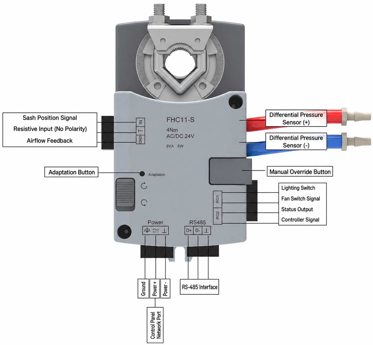
The interface drawing identifies the position input, airflow feedback, pressure connections, relay outputs, power, panel, and RS-485 groups. Match the labels and terminal arrangement to the supplied hardware revision before field wiring. The diagram supports coordination; it does not establish unlisted contact ratings, signal ranges, communication settings, or cable limits.
| Interface | Visible Connection | Function | Field Check |
|---|---|---|---|
| Position / airflow signal | IN1, common, airflow-feedback group | Receives the resistive sash signal and provides the airflow-feedback interface | Confirm scaling, zero, full travel, common reference, and direction |
| Pressure sensing | Positive and negative tube connections | Connects the differential-pressure airflow measurement arrangement | Confirm pickup, tube polarity, leaks, zero, and calibration |
| RO1 / RO2 | Two relay-output groups | Supports project-assigned status, interlock, alarm, or lighting functions | Confirm contact rating, normal state, load, and failure behavior |
| Power | Protective earth, 24 V supply, common | Provides the controller and integrated actuator supply | Confirm AC/DC revision, capacity, protection, grounding, and conductor size |
| RS-485 | D+, D-, and communication reference | Supports Modbus RTU communication | Confirm address, baud rate, parity, topology, termination, and register map |
| Operator panel | Independent RJ12 interface | Connects the approved local fume hood panel | Confirm panel model, cable, mounting, indication, alarms, and supplied scope |
Control and Communication Coordination
Define how each RO output, local-panel function, and BMS point behaves during startup, normal operation, reduced airflow, low-condition alarm, emergency or override operation, sensor failure, communication loss, power interruption, and restart. Approve the Modbus address, baud rate, parity, register map, remote command permissions, override priority, network termination, and point ownership. Point-to-point communication success does not prove that sash direction, airflow scaling, damper movement, or hood response is correct.
Calibration, Functional Testing, and Acceptance
Record the position signal with the sash closed, at normal working height, and at the maximum approved opening. Establish the opening-to-airflow relationship from the actual hood geometry and airflow schedule. Verify pressure-tube polarity, feedback zero and scaling, damper direction, usable travel, and response at minimum, normal, maximum, energy-saving, and emergency states. Final acceptance should measure face velocity at the required sash positions and check recovery after movement, alarms, RO functions, panel indication, BMS points, remote commands, failure behavior, and restart. Record the configuration, setpoints, test conditions, results, and future calibration responsibility.
How to Select and Specify the Controller
Define the Hood Control Objective First
Write the required hood behavior before selecting the controller hardware. Identify the hood and sash type, clear opening geometry, target face velocity, minimum/normal/maximum/energy-saving/emergency airflow, alarm conditions, override, and expected damper and fan response. Confirm that sash position will define demand and actual exhaust airflow will provide correction. If direct face velocity, room pressure, automatic sash movement, or another variable is the primary control objective, this is not the correct selection path.
Match the Position Sensor, Damper, and Airflow Feedback
Define the position sensor characteristic, mounting, useful travel, zero, full scale, and behavior if the cable or signal fails. For the damper, state body size and material, shaft profile, required torque and angle, direction, pressure condition, stops, mounting limits, and chemical-exposure review. Add the airflow pickup, tubing, calibration relationship, available pressure, fan or VFD sequence, 24 V supply, RO functions, local panel, and RS-485/Modbus requirements. The proposed controller should be traceable to these fields so a later change triggers technical review.
Confirm the Project Sequence and Responsibility Matrix
The final specification should describe startup, sash movement, normal and reduced airflow, emergency or override operation, low-condition alarm, local acknowledgement, signal loss, communication loss, power loss, restart, and BMS commands and feedback. Allocate responsibility for the controller, position sensor, damper, airflow pickup, panel, fan or VFD, power, mounting, tubing, wiring, network programming, balancing, face-velocity testing, documentation, and ongoing calibration. The approved schedule, mounting drawing, wiring diagram, point list, and control sequence then govern manufacture, installation, commissioning, and service.
Datasheet and Project Review
Technical Data to Confirm before Approval
Use the visible specifications and dimension drawing for initial comparison, then confirm the exact configuration for every fume hood tag. The review should resolve sash type and travel, position-sensor characteristic, target face velocity, airflow states, damper and shaft interface, required torque and rotation, airflow-pickup arrangement, feedback scaling, available pressure, fan sequence, supplied controller revision, 24 V source, RO assignments, panel compatibility, communication settings, alarm limits, failure behavior, mounting hardware, tubing, wiring access, and ambient conditions. For chemical exhaust, also review every exposed damper and sensing component against the actual air stream.
Power data require explicit revision control. The manual’s maximum DC and AC supply values and the lower figures shown on the visible product nameplate must remain separate until the supplied hardware is identified. The same rule applies to any missing sensor range, control accuracy, response, relay rating, enclosure protection, or Modbus register information: confirm it in the approved technical package or leave it unresolved rather than converting an assumption into a specification.
Technical Submittal Contents
The submittal should allow the hood manufacturer, ventilation designer, controls contractor, installer, and commissioning team to identify the same delivered configuration. Include the hood control tag, controller and actuator model, sash sensor, damper, mechanical interface, power, position input, airflow-feedback arrangement, relay functions, local panel, RS-485/Modbus scope, setpoints, alarms, energy-saving and emergency behavior, failure sequence, and supplied or excluded components. Add the data sheet, dimension and mounting drawing, controller-specific wiring diagram, hood and airflow schedule, point list, control sequence, and commissioning record. Any later change to sash geometry, sensor, damper, airflow pickup, signal convention, or operating sequence should trigger coordinated review before installation.
Related Products
Related Exhaust-Airflow Control Devices
The controller must be selected with an airflow-control device that matches the hood’s mechanical and airflow requirements. The VAV Butterfly damper is the relevant device when a rotating blade can be matched to the integrated actuator’s shaft, torque, angle, mounting, pressure condition, and airflow schedule. If the project specifies a pressure-independent Venturi mechanism, evaluate the VAV Venturi Air Valve and its corresponding actuator and control architecture instead. Neither valve body is automatically included with this controller.
Related Fume Hood Controls and Accessories
Another control product may be required when the project uses direct face-velocity feedback, an external actuator, or automatic sash movement. Review the Fume Hood Controllers category by primary input and actuator architecture. A complete position-based installation also needs a compatible Fume Hood Sash Position Sensor, and may require a local panel, airflow pickup, tubing, fan interface, and installation hardware from the appropriate Fume Hood System Accessories scope.
Frequently Asked Questions
What does a sash position fume hood controller control?
The controller receives a resistive signal representing sash travel, combines the opening relationship with the configured face-velocity objective, and calculates the required exhaust airflow. It commands its integrated rotary actuator to move a compatible butterfly damper, then uses actual-airflow feedback to correct the result. It does not create airflow or replace the hood, sash sensor, damper body, fan, ductwork, airflow pickup, balancing, or final face-velocity test.
Does this controller measure face velocity directly?
No separate velocity probe at the hood opening is the confirmed primary input for this architecture. Sash position establishes demand, and exhaust-airflow feedback corrects the damper output. The configured airflow and opening relationship is intended to support the selected face-velocity condition, but actual face velocity must be measured across the hood opening during commissioning. Projects that require a direct velocity sensor as the primary control input should evaluate the dedicated face-velocity controller.
Why is airflow feedback needed when sash position is already known?
Sash position indicates that the required airflow should change, but it cannot prove what the exhaust branch delivers. The same damper angle can produce different airflow when fan operation, duct pressure, filters, branch resistance, or system balance changes. Differential-pressure-based airflow feedback lets the controller correct its command against the measured condition. Reliable correction still requires a suitable pickup, correct tubing polarity, valid scaling, enough damper authority, and field calibration.
Can the integrated actuator control any butterfly damper?
No. The damper shaft profile, coupling, required rotation, blade torque at the operating pressure, mechanical stops, mounting orientation, and available clearance must match the approximately 3-second, 4 N·m rotary actuator. A larger, high-friction, spring-return, linear-motion, or nominated-brand damper arrangement may require another actuator and a split controller. Damper airflow capacity, leakage, materials, connections, and chemical compatibility are separate specifications.
Can one controller be used with horizontal or multiple sashes?
Only after the opening calculation and sensor method are approved. The controller has one confirmed resistive position input. A vertical sash can usually be represented by one continuous travel signal, but horizontal panels or multiple independently moving sashes require a method for calculating total effective opening area. Do not parallel several sensors or substitute a simple contact unless the input circuit and control sequence have been specifically engineered and tested.
What power, outputs, panel, and BMS interfaces are available?
The confirmed interfaces include 24 V AC/DC power, two project-assigned RO outputs, an independent RJ12 local-panel connection, and RS-485 with Modbus RTU support. The final package must define the applicable power capacity for the supplied revision, relay contact ratings and assignments, panel model and cable, communication address and settings, register map, point ownership, override priority, alarm reporting, loss-of-communication behavior, and return to local control.
What information is required for a project-ready quotation?
Provide the fume hood tags and quantities, hood and sash arrangement, clear opening and travel, target face velocity, minimum/normal/maximum/energy-saving/emergency airflow, position-sensor details, butterfly-damper size and shaft, torque and rotation, available pressure, airflow pickup and tubing, fan sequence, 24 V supply, RO functions, local panel, Modbus/BMS requirements, alarm and failure sequence, mounting drawings, destination, and documentation requirements. The documented configuration should state the controller revision, interfaces, supplied and excluded scope, commissioning responsibility, and pricing.
Contact the Xicheng Engineering Team Today.
Send the fume hood and sash schedule, position-sensor details, target face velocity, minimum/normal/maximum/energy-saving/emergency exhaust airflow, butterfly-damper shaft and torque, airflow pickup, available pressure, power, panel and Modbus requirements, alarm and failure sequence, drawings, quantity, and destination. XICHENG will return a proposed sash position fume hood controller configuration, applicable specifications, mechanical and electrical interfaces, supplied and excluded scope, unresolved technical items, commissioning requirements, and commercial pricing.
🎯 Shenzhen Office: No. 34 Zhenxing Road (Shengtaian Heavy Industrial Park B), Loucun, Guangming New District, Shenzhen, Guangdong, China
☎️ WhatsApp: +86 181 2647 8161
📬 Engineering Mailbox: fanalax34@gmail.com