


Description
Fume Hood Airflow Monitor Overview
What the Monitor Does
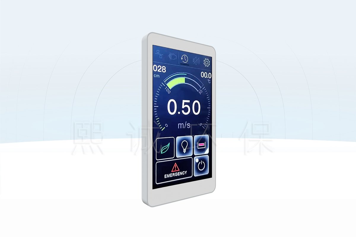
The FHM-5T fume hood airflow monitor is the local display and operator interface for a compatible XICHENG FHC-series controller. Its 5-inch touchscreen brings the measurements, status information, alarms and approved commands that matter during daily hood use to the front fascia. Operators can view face velocity, sash opening, airflow indication and exhaust temperature without opening a control enclosure or relying on a remote building-management screen.
The panel exchanges information with the connected controller. It does not create the measurements shown on screen and does not regulate exhaust airflow on its own. The face-velocity sensor, sash-position input, controller, damper or Venturi air valve, actuator and exhaust system must be selected and commissioned as a complete control path. This distinction is important when replacing a panel or specifying a monitor for a new hood: matching the screen size alone does not establish electrical, communication or functional compatibility.
Choose This Interface When
This fume hood monitor is suited to projects that need more than a simple normal/alarm indicator. It provides a full-color operating interface for hoods where users or service staff need to see several system values, distinguish alarm types and use authorized local commands. It can support either a butterfly-damper or Venturi-valve control arrangement when paired with the applicable controller configuration.
- The hood user must see face velocity together with sash position, airflow indication or exhaust temperature.
- The operating sequence includes visual alarms and an audible warning that can be acknowledged at the hood.
- Lighting, equipment start/stop, energy-saving mode or emergency exhaust must be available through the local interface.
- An automatic-sash system is present and its open, close or temporary-disable commands need to appear on the panel.
- The hood fascia can accept the 143.5 x 75.5 mm cutout and the selected PP or steel mounting arrangement.
A simpler panel may be more appropriate when the project only needs a small number of fixed pushbuttons and status indicators. The FHM-5T should be selected because its display depth and operating functions are required, not merely because a touchscreen is available.
Information Needed Before Configuration
For each hood, identify the connected controller, valve or damper type, face-velocity input, sash-position method, exhaust-temperature input, alarm requirements and the commands that operators may use. State whether the project includes automatic sash movement, an occupancy sensor, anti-pinch protection, emergency exhaust, energy-saving operation and BMS coordination. The fascia material, available cutout area, cable route and service access must also be shown on the hood drawing.
These inputs determine which values and buttons are enabled, how alarms behave and which mounting hardware is used. They also prevent a replacement monitor from being ordered against an unknown controller or an undocumented control sequence.
Display, Alarm and Operator Functions
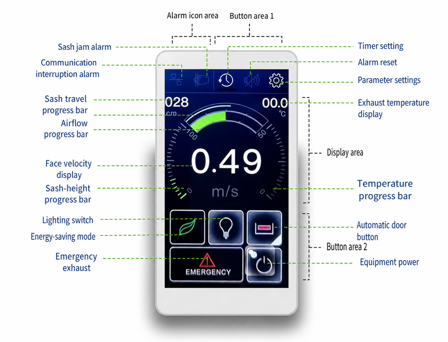
The touchscreen organizes the information needed during routine hood operation into three practical areas: alarm icons at the top, live measurements in the central display and operating commands at the bottom. This layout lets the operator distinguish a low face-velocity condition from a sash or communication problem before deciding whether to stop work, close the sash or request service.
Measurements and Status Shown at the Hood
The main display can show face velocity in metres per second, sash opening or travel in centimetres, an airflow progress indication and exhaust temperature. Progress bars provide a quick visual reference, while the numerical values support a more precise operating check. The source interface also shows how the face-velocity indication changes state when the measured value falls outside the configured normal range.
These values come from the connected control system. A face-velocity reading depends on the installed sensor and its scaling; sash opening depends on the position input and calibrated travel; exhaust temperature depends on the configured temperature input. During commissioning, each screen value should therefore be compared with the related field condition rather than accepted solely because it appears plausible.
Alarm Indications and Operator Response
The fume hood face velocity monitor provides visual alarm information and an audible warning path for conditions defined in the controller configuration. The documented interface includes low face velocity, excessive sash opening, high exhaust temperature, communication interruption and sash obstruction or anti-pinch indications. The last condition applies when automatic-sash hardware and a safety sensor are part of the hood system.
The alarm-reset control silences or acknowledges the panel indication as configured; it does not correct the underlying fault. A low face-velocity alarm calls for the sash and exhaust condition to be checked. A communication alarm calls for power, cable and controller status to be checked. A sash obstruction alarm requires the closing path and safety input to be inspected before automatic motion resumes. The site operating procedure should define when work must stop and who is authorized to reset or service each condition.
Authorized Local Commands
The panel can present controls for hood lighting, equipment start/stop, emergency exhaust and energy-saving mode. When an automatic sash system is fitted, the interface can also provide sash open, sash close and temporary automatic-control disable commands. A timer and parameter-setting area are available for the applicable system configuration.
Each button sends a command into the configured control sequence. Emergency exhaust, for example, is intended to call the system’s emergency operating state; the panel itself does not produce airflow. Automatic-sash commands require the separate motor, position feedback and safety devices. Before handover, test every enabled button and confirm how local commands interact with the controller and any BMS-level instruction.
Key Specifications and Panel Dimensions
The FHM-5T combines a compact fascia footprint with a high-resolution color display. Confirm the electrical supply, environmental limits and hood cutout before finalizing the front-panel drawing. The values below describe the monitor itself; controller, sensor and actuator specifications are selected separately.
| Specification | FHM-5T Value |
|---|---|
| Product role | Fume hood airflow monitor and touchscreen operator panel |
| Display | 5-inch IPS touchscreen |
| Resolution | 1280 x 720 |
| Power supply | DC 5 V, +/-10% |
| Power consumption | Less than 2 W |
| Operating environment | 0 to +50 deg C; 10-95% RH, non-condensing |
| Storage environment | -20 to +50 deg C; 10-95% RH, non-condensing |
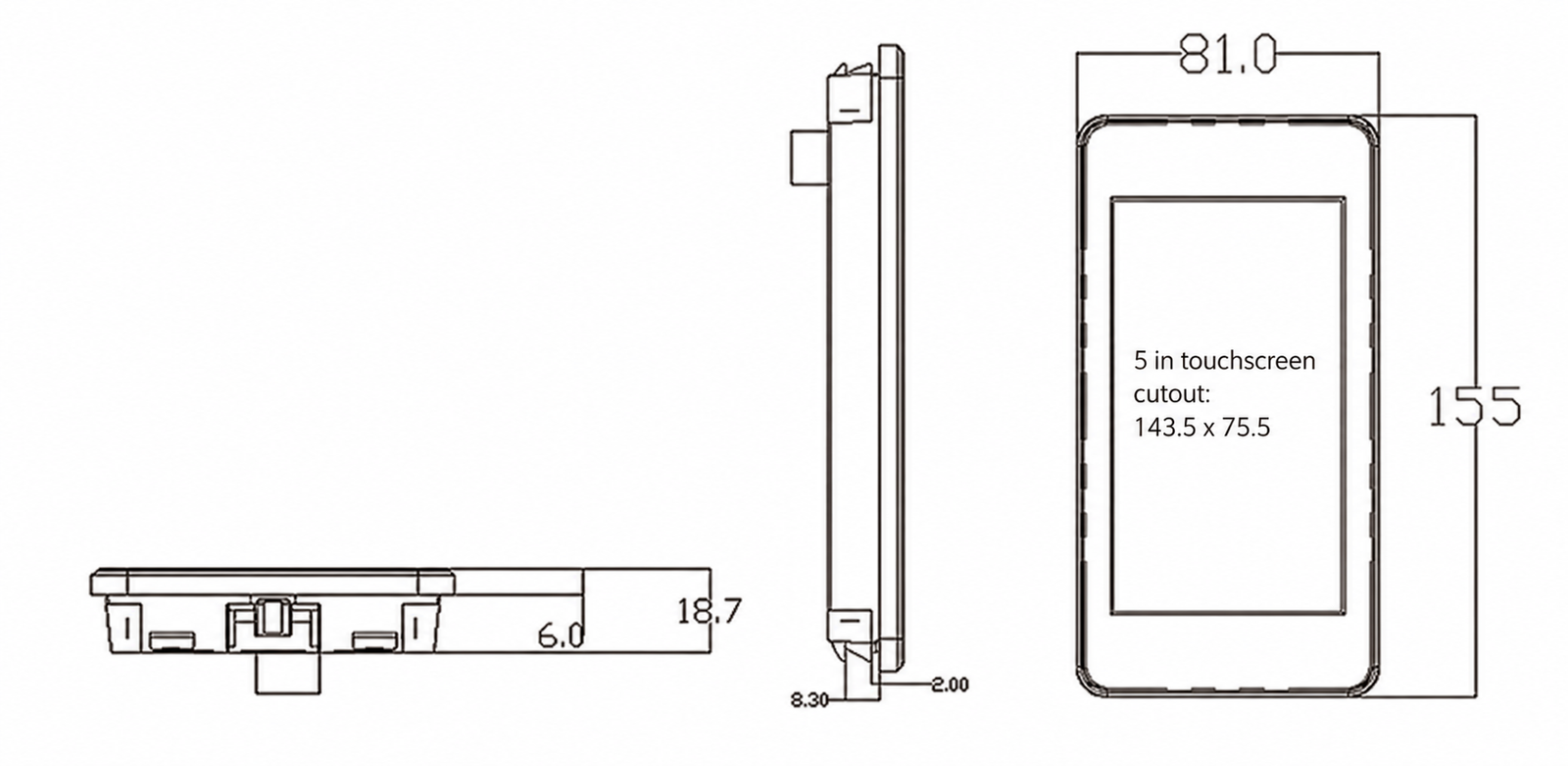
| Panel face | 81.0 x 155 mm |
| Reference depth | 18.7 mm |
| Recommended cutout | 143.5 x 75.5 mm |
| Mounting context | Documented arrangements for PP and steel fume hood fronts |
| System connection | Compatible XICHENG FHC-series controller configuration |
Electrical, Display and Environmental Data
The monitor requires a regulated DC 5 V supply within the stated tolerance and consumes less than 2 W. Keep its power and communication wiring identifiable to the assigned hood controller. The 0 to +50 deg C operating range and non-condensing humidity limit apply to the installed panel environment, so the fascia location should be protected from direct chemical splash, condensate and heat sources outside that range.
The 1280 x 720 IPS display supports the multi-value operating screen and alarm icons described in the product documentation. Screen resolution does not determine measurement accuracy; accuracy and response depend on the connected sensors, controller configuration and airflow-control equipment.
Cutout, Depth and Front-Panel Fit
The reference face is 81.0 mm wide and 155 mm high, with an 18.7 mm reference depth. The documented cutout is 143.5 x 75.5 mm. Verify the final production unit and hood drawing before machining because the surrounding lip, rear connector, cable bend and fastening method require space beyond the rectangular opening.
Leave enough rear access to connect and inspect the cable without removing unrelated hood components. For replacement work, measure the existing opening and confirm the controller connection before assuming that the FHM-5T will cover the old cutout or use the same wiring.
Controller Interface, Signals and Data Path
The FHM-5T sits between the hood user and the configured control system. It receives operating values and status from the controller, presents them on screen and returns authorized commands or parameter changes. The interface should therefore be scheduled with the controller and field devices, not treated as a universal replacement display.
Where Displayed Values Come From
Face velocity is supplied through the configured air-velocity sensing path. Sash opening comes from the installed position sensor and calibrated closed/open points. Exhaust temperature uses the applicable analog input and scaling. The airflow progress indication is calculated within the configured hood-control arrangement, using controller information rather than a sensor built into the touchscreen.
For a new system, define each displayed field and its source on the controls schedule. For a replacement, identify the existing controller, sensor types and scaling before removing the old panel. A communication link can transfer an incorrect value if the field input or controller parameter is wrong, so the displayed result must be checked against the actual hood during commissioning.
Commands, Communication and Control Priority
The monitor can issue local commands for equipment power, lighting, energy-saving operation, emergency exhaust and automatic sash movement when those functions are enabled. The connected controller performs the sequence and drives the related field output. Local commands must be coordinated with any room controller or BMS instruction so that the approved safety priority is preserved.
The source configuration includes controller communication settings for device address, baud rate and parity under a Modbus-labeled menu. Final protocol, address and network responsibility must match the delivered controller package and project point list. Do not assume that the presence of a communication menu makes every controller version or BMS network directly interchangeable.
Parameter Access and Backup Functions
The touchscreen provides access to controller settings for the applicable system configuration. Documented menus include general airflow settings, butterfly-damper or Venturi-valve selection, position and air-velocity input scaling, sash limits, actuator control/feedback fields, butterfly-damper PID settings, automatic-sash behavior and communication parameters.
The interface can copy controller parameters to the panel and download a stored set back to the controller. This function can simplify service or replacement, but it requires disciplined version control. Record the hood tag, controller model, parameter date and approved settings before downloading a backup. After restoration, retest the sensor values, sash limits, alarms, valve or damper response and every enabled command; a completed download is not a functional acceptance test.
Fume Hood System Fit and Panel Selection
The monitor can serve different fume hood control arrangements because it presents controller data and operator commands rather than imposing one valve mechanism. Product fit is determined by the connected controller, field inputs, exhaust-control device and required operator workflow.
Butterfly-Damper and Venturi-Valve Systems
The FHM-5T source configuration includes setup paths for a modulating butterfly damper and a Venturi air valve. In a butterfly-damper arrangement, the controller uses the configured damper size, actuator signals and control settings to regulate exhaust. In a Venturi-valve arrangement, the controller and valve package use the applicable airflow and pressure-related configuration. The touchscreen can display the resulting hood information and expose approved commands in either arrangement.
The panel does not make these two control paths mechanically or electrically interchangeable. Confirm the controller version, valve or damper type, actuator interface, sensing method and operating range for each hood. If the project changes the exhaust-control device, review the controller and field wiring as well as the display configuration.
Automatic-Sash and Energy-Saving Functions
Automatic-sash buttons and anti-pinch alarm indications are relevant only when the hood includes the corresponding sash controller, motor, position feedback and safety sensor. The monitor can provide open, close and temporary-disable commands, while the sash-control hardware performs the movement and protective response. The energy-saving command can place the configured system into its reduced operating state; the actual airflow target and sash action remain part of the approved controller sequence.
For occupancy-based operation, define what happens when a person approaches, remains at or leaves the hood. The panel should show the resulting state clearly, but occupancy detection and obstruction protection remain separate field inputs. Do not enable an automatic-sash button until travel limits, direction, obstruction response and a manual recovery path have been tested.
FHM-5T Versus Other Operator Panels
Select the FHM-5T when operators need a 5-inch graphical view of several measurements, progress indications, alarms and operating commands. A glass touch fume hood control panel is a different interface choice for projects centered on a long-strip local panel and defined touch keys. A Bluetooth fume hood control panel should be evaluated only when its confirmed wireless or mobile setup path is required for the selected version.
The related air velocity sensor supplies a measurement input and is not an alternative operator panel. Choose among these products by function: the sensor measures, the controller applies the control logic and the FHM-5T presents operating information and authorized user commands.
Installation, Setup and Commissioning
Installation begins with the hood fascia drawing and control architecture. Confirm the opening, rear clearance, cable route, assigned controller and enabled functions before the panel is mounted. Commissioning then proves that each displayed value, alarm and command corresponds to the correct field condition.
PP and Steel Fume Hood Mounting
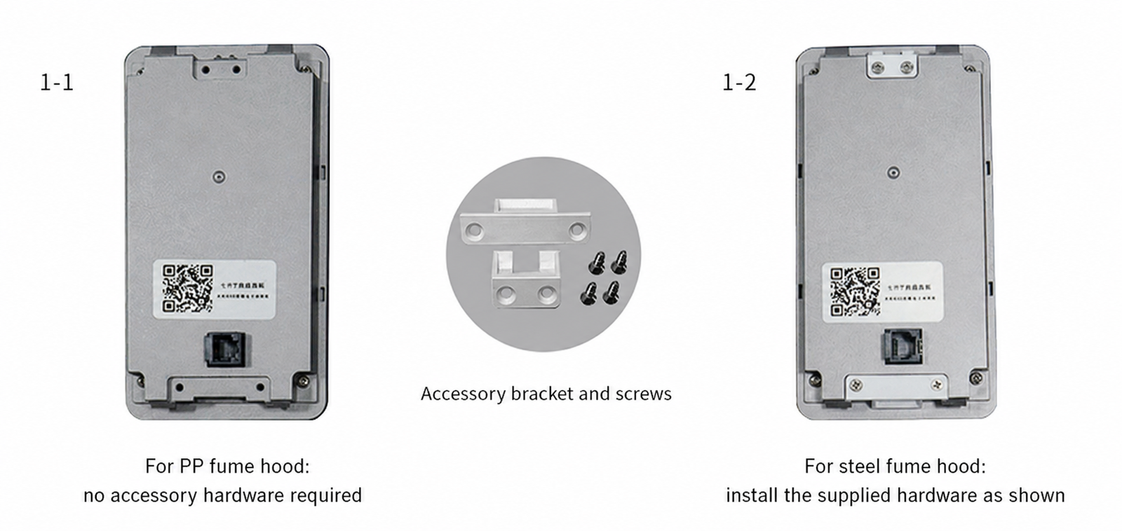
The source installation drawing distinguishes between PP and steel hood fronts. The PP arrangement is shown without the supplied accessory bracket, while the steel arrangement uses the bracket and screws in the illustrated positions. Follow the delivered mounting details for the actual panel and hood construction; do not transfer the steel hardware arrangement to a PP fascia without confirming the assembly.
Keep the panel face level and protect the display during hood fabrication. The rear connector and cable must remain accessible after installation. Where a replacement opening is larger than the documented cutout, use an engineered adapter or revised fascia detail rather than relying on the panel lip to cover an unsupported edge.
Electrical and Communication Checks
Verify the DC 5 V supply polarity and voltage before connecting the monitor. Route the panel cable so that it is protected from sharp sheet-metal edges, moving sash parts and service access to other components. Label both ends with the hood tag and controller connection.
After power-up, confirm stable communication with the assigned controller. Check the device and communication settings against the delivered controls schedule before changing parameters. A communication alarm should be tested by an approved method so the operator and service team know how the failure appears and how communication is restored.
Functional Acceptance at the Hood
Compare the displayed face velocity with the commissioned measurement at the sash opening and verify that the sash-height indication follows the actual travel. Check the exhaust-temperature input when it is used. Exercise each alarm at its defined test condition and confirm both the visual indication and audible response.
Test lighting, equipment power, energy-saving mode and emergency exhaust through the complete control path. If automatic sash functions are enabled, verify open, close, stop or disable behavior, travel limits, occupancy response and anti-pinch operation. Record the final controller version, parameter backup, enabled screen functions and test results for the hood tag. The monitor is ready for use only after the field system, not just the touchscreen, passes this functional check.
How to Configure the Fume Hood Monitor
A project-ready FHM-5T schedule defines the information shown on screen, the commands available to the operator and the equipment behind each function. Start with the hood control sequence, then confirm the panel layout and mounting. This avoids ordering a visually correct monitor that cannot communicate with the installed controller or cannot support the required operating path.
Define the Required Display and Control Functions
List the measurements that must be visible during normal operation: face velocity, sash opening, airflow indication and exhaust temperature. Then define the alarms required at the hood, including their visual state, audible behavior, reset permissions and operator response. If a value or alarm is not required, remove it from the functional schedule instead of leaving an unexplained or inactive screen element.
Specify which local commands are needed. Lighting and equipment start/stop may be basic operating functions, while emergency exhaust, energy-saving mode and automatic sash commands require a defined system sequence. State who may access parameter settings and whether a password-controlled service level is required.
Confirm the Connected Equipment
Identify the FHC-series controller and software or hardware version, the face-velocity sensor, sash-position input, damper or Venturi air valve, actuator, exhaust fan interface and any automatic-sash components. Provide the BMS point list when local and supervisory commands share responsibility. For replacement work, include photographs of the existing panel, rear connector, controller label and terminal wiring.
The hood-front drawing should show the 143.5 x 75.5 mm cutout, available depth, fascia material and cable path. State whether the panel will be installed on a PP or steel hood so the mounting arrangement can be confirmed before fabrication.
Information Required for a Quotation
Send the hood quantity and tags, project location, controller model, required display fields, alarm list, local button functions, valve or damper type, sensor inputs, automatic-sash scope, communication requirements, fascia material, cutout drawing and delivery destination. Include the control schematic and sequence of operation when available.
XICHENG will use this information to identify the applicable panel configuration, mounting arrangement and controller interface, and to list the included monitor and supporting documents in the quotation. Field sensors, controllers, sash-drive components and exhaust devices should be itemized separately unless they are explicitly included in the ordered system scope.
Frequently Asked Questions
Is the FHM-5T a standalone airflow sensor?
No. The FHM-5T is a fume hood airflow monitor and operator panel that displays information received through the compatible controller. Face velocity requires the appropriate air velocity sensor, controller configuration and field commissioning.
Can it show face velocity and sash opening together?
Yes. The documented interface can show face velocity, sash opening or travel, airflow indication and exhaust temperature on the operating screen. Each field must be connected to the applicable input and scaled in the controller before it can be relied on.
Which alarms can appear on the panel?
The source interface includes low face velocity, excessive sash opening, high exhaust temperature, controller-communication interruption and sash obstruction or anti-pinch indications. The available alarms depend on the sensors and automatic-sash functions included in the configured hood system.
Can the panel operate lighting and emergency exhaust?
The interface can provide lighting, equipment power, energy-saving and emergency-exhaust commands. The connected controller and field outputs perform those actions, and their priority must follow the approved hood sequence.
Can it be used with butterfly-damper and Venturi-valve systems?
The product documentation includes configuration paths for both modulating butterfly-damper and Venturi-valve arrangements. Compatibility depends on the selected FHC-series controller, actuator or valve interface, sensors and project control logic; the touchscreen alone does not convert one system type into the other.
What panel cutout is required?
The documented cutout is 143.5 x 75.5 mm, with an 81.0 x 155 mm panel face and an 18.7 mm reference depth. Confirm the delivered unit, rear connector clearance and PP or steel mounting detail before machining the hood fascia.
What should be checked during commissioning?
Compare displayed measurements with the actual hood condition, test each alarm, verify every enabled command and confirm stable controller communication. Automatic-sash movement, obstruction response, energy-saving behavior and emergency exhaust must be tested through their complete field control paths when included.
Contact the Xicheng Engineering Team Today
Send the hood tags, controller model, required screen values, alarm and button list, valve or damper type, sensor and automatic-sash scope, panel cutout drawing, quantity and destination. The engineering team will confirm the suitable FHM-5T configuration, mounting arrangement, interface requirements and quoted supply scope.
Shenzhen Office: No. 34 Zhenxing Road (Shengtaian Heavy Industrial Park B), Loucun, Guangming New Dist, Shenzhen, Guangdong, China
WhatsApp: +86 18126478161
Engineering Mailbox: fanalax34@gmail.com