


Description
Glass Touch Fume Hood Control Panel for Local Operation
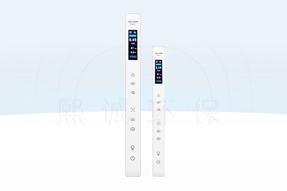
The FHM-L1 glass touch fume hood control panel gives the operator a compact view of hood conditions and direct access to frequently used commands. It communicates with a compatible FHC-series controller through RS-485 and presents the data and operating states supplied by that controller. The narrow 28.8 mm face is designed for integration into a fume hood side post or control fascia where a conventional wide touchscreen would occupy too much space.
Choose This Panel When
The long-strip panel suits a fume hood that requires local face-velocity or airflow indication, sash information and command keys in a single vertical interface. It is particularly useful when emergency exhaust and alarm mute must remain one-touch functions rather than menu items.
- The hood uses a compatible FHC-series controller.
- The operator needs face velocity or airflow, sash height, temperature and state at the hood.
- Emergency exhaust, energy-saving, sash, lighting and power commands are required locally.
- The cabinet can accommodate the illustrated 286.1 mm panel and connector pass-through.
- RS-485 wiring and the RJ11-6P connection can be routed separately from power conductors.
Panel and Controller Have Different Roles
The FHM-L1 is an operator interface, not an independent airflow monitor or control processor. It displays values received from the controller and sends touch commands back to it. Sensors, control algorithms, actuator outputs, alarm logic and the final ventilation sequence remain in the connected FHC system. This separation should be reflected in the wiring diagram, commissioning scope and spare-parts schedule.
What the Operator Can See at a Glance
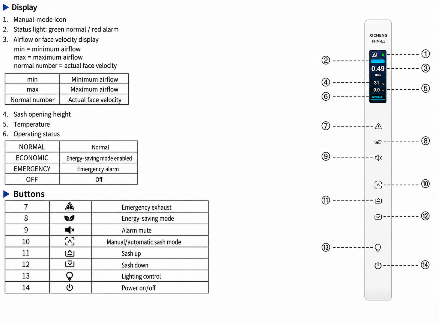
The color screen can show face velocity or airflow, sash opening height, temperature and the current NORMAL, ECONOMIC, EMERGENCY or OFF state. A green status indication represents normal operation and a red indication identifies an alarm. The panel can display low or high flow, excessive sash opening and high-temperature conditions generated by the controller.
Key Specifications and System Boundary
| Selection Item | FHM-L1 Product Data |
|---|---|
| Product function | Local display and touch-command panel for compatible FHC controllers |
| Communication | RS-485 |
| Controller connector | RJ11-6P |
| Touch inputs | Eight dedicated function keys |
| Displayed values | Face velocity or airflow, sash height, temperature and operating state |
| Panel dimensions | 286.1 x 28.8 x 8.0 mm (L x W x H) |
| Operating environment | 0-50 deg C; 10-90% RH, non-condensing |
| Installation | Wall or fascia baseplate with two screw/rivet fixing points |
Compatibility Must Be Confirmed
A matching connector does not by itself prove controller compatibility. Confirm the FHC controller model, communication wiring, firmware functions and available sash-control outputs. The panel can only display values and execute commands that the paired controller supports and has been configured to expose.
Data the Panel Does Not Generate
The panel does not contain the face-velocity sensor, sash position sensor or temperature sensor described by its display fields. It also does not establish alarm limits by itself. The measured values, thresholds and response sequence originate in the connected control system and must be verified during hood commissioning.
Environmental and Cleaning Considerations
Install the panel within the stated non-condensing environment and keep the connector area protected from liquid ingress. Use a cleaning method suitable for the glass face and avoid flooding the panel edge or using tools that can scratch the touch surface. Isolate system power before removing the panel from its baseplate.
Display Information, Modes and Alarm Indication
The color display organizes the information an operator needs during normal hood use: current face velocity or airflow, sash opening height, temperature and operating state. The displayed values come from the paired FHC controller and its connected sensors. During commissioning, each field should be checked against the controller engineering screen or an independent measurement so the operator panel does not present an unverified value.
Face Velocity or Airflow Display
A normal numerical value represents the actual face velocity or airflow value supplied by the controller. The screen can also show min or max when the controlled value is outside the configured range. These indications help the user recognize a change, but they do not replace hood commissioning or periodic containment checks.
Operating States
NORMAL identifies ordinary operation. ECONOMIC indicates that the energy-saving mode is active. EMERGENCY identifies the emergency exhaust state, and OFF shows that the hood control function is switched off. The control designer should document what each mode does to the exhaust valve, fan, sash and lighting because the panel label alone does not define the complete sequence.
Alarm Conditions and Acknowledgement
The panel can indicate normal flow, low or high flow, excessive sash opening and high temperature when these conditions are generated by the controller. A green status light represents normal operation; a red status light identifies an alarm. The mute key silences the audible indication but does not clear the cause. The visual alarm should remain until the measured condition returns to the permitted range or the controller is reset according to the commissioned sequence.
Eight Touch Keys for Local Fume Hood Operation
Dedicated keys reduce the number of steps required for time-sensitive or frequently used commands. Emergency exhaust, alarm mute and sash movement remain directly accessible, while their actual effect depends on controller configuration, permissive inputs and connected equipment.
Emergency Exhaust and Energy-Saving Commands
The emergency exhaust key requests the controller’s emergency operating mode. Confirm whether that mode drives an exhaust valve to its configured emergency position, commands a fan or performs another project-specific action. The energy-saving key requests the lower-energy operating state; it should only reduce airflow when the controller’s occupancy, sash and safety conditions permit the transition.
Manual and Automatic Sash Functions
The manual/automatic key changes the sash-control mode, and the up/down keys request movement. These commands require a compatible automatic sash controller, motor and safety inputs. The panel does not supply motor power and must not bypass the obstruction-protection sequence. When automatic sash functions are not included, the keys should be disabled or their behavior clearly documented.
Lighting, Power and Alarm Mute
The lighting key controls the assigned hood-lighting output through the FHC controller. The power key switches the configured hood-control state rather than physically isolating all electrical circuits. Maintenance personnel must still use the equipment disconnect before opening the panel or servicing the hood. Alarm mute acknowledges the sound only; it is not a reset for low face velocity, excess sash height or high temperature.
Operator Acceptance Check
Test every enabled key after wiring and parameter setup. Confirm the displayed state, controller response and actual connected-device action for each command. Also verify that disabled or unsupported functions cannot produce an ambiguous indication. This check is especially important when the same panel is used with different FHC controller configurations.
Panel Dimensions, Cutout and Wall Installation
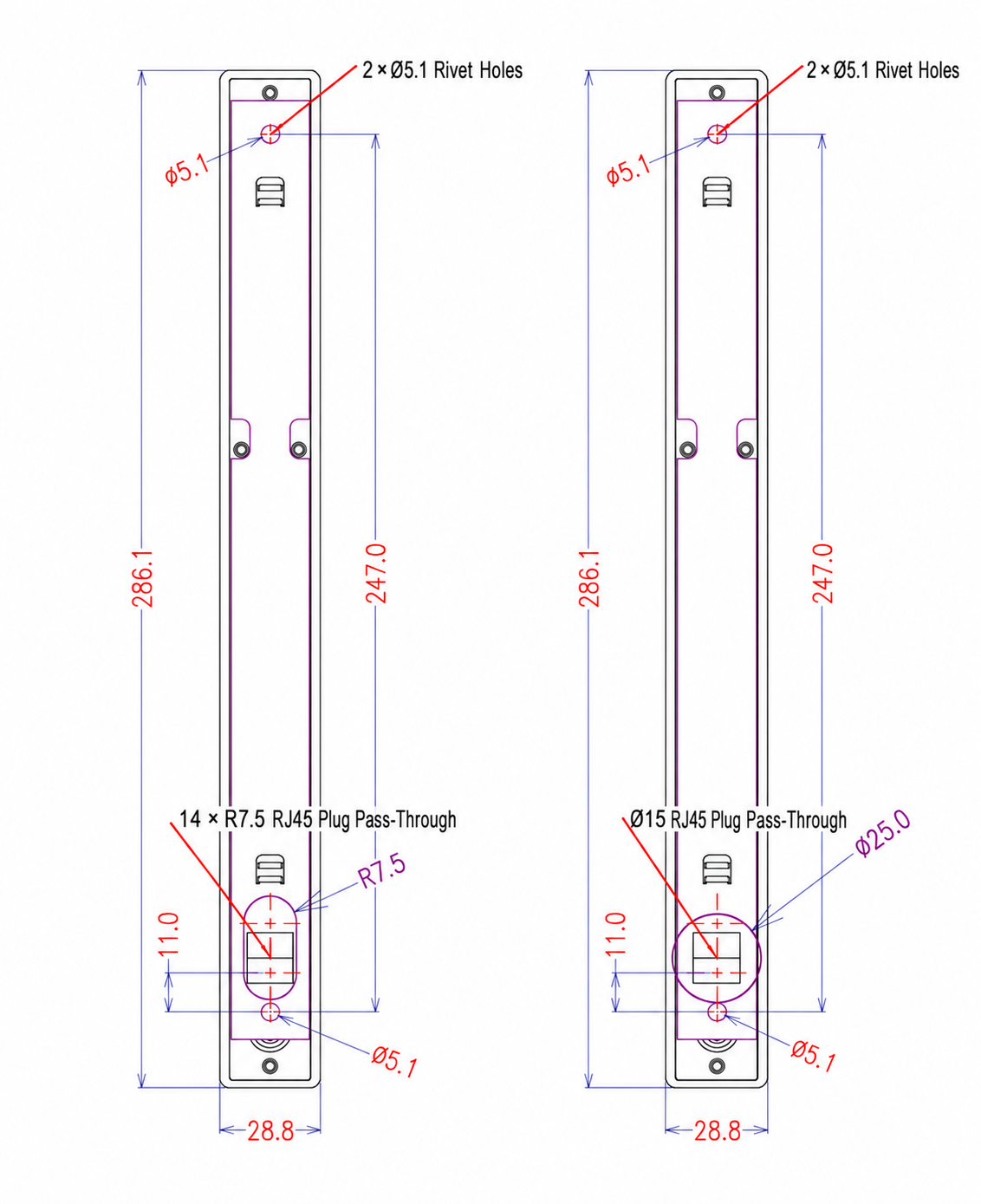
The FHM-L1 measures 286.1 x 28.8 x 8.0 mm. The narrow enclosure needs a straight mounting surface, correct fixing-hole spacing and enough rear clearance for the RJ11-6P plug and cable bend. Check the cabinet profile before cutting because the drawing provides two alternative connector pass-through layouts.
Choose One Connector Pass-Through
The left drawing shows a 14 x R7.5 slot-style RJ45 plug pass-through; the right drawing shows a circular pass-through referenced as 15 mm with a 25 mm surrounding diameter. Use the arrangement that matches the actual plug, fascia construction and installation method. Do not combine both alternatives on one panel opening unless a revised fabrication drawing calls for it.
Baseplate Installation Sequence
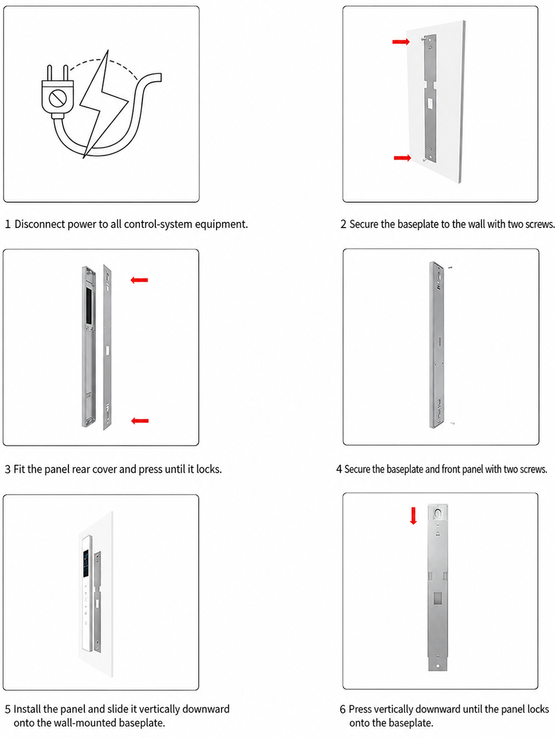
Disconnect power to the complete control system before installation. Fix the baseplate with two screws, fit the rear cover, secure the baseplate and front panel, then slide the panel vertically downward until it locks. The communication cable should be connected without twisting the plug or forcing the cable against the enclosure edge.
Installation Inspection
After mounting, check that the glass face sits flat, the touch areas respond without excessive pressure and the panel cannot lift off the baseplate during use. Inspect the cable for strain and verify that the connector remains serviceable. Restore power only after the controller and panel wiring have been checked.
RS-485 Integration and Product Selection
The FHM-L1 exchanges data with the FHC controller through RS-485 and uses an RJ11-6P connection. Select it as part of a defined controller package rather than as a generic replacement for any long-strip panel. Communication pinout, controller firmware and enabled functions must match.
Commissioning Sequence
Confirm communication first, then verify each displayed field and command. Check face velocity or airflow against the controller value, move the sash through its calibrated range, compare the temperature display with the connected sensor and trigger permitted alarm tests. Record the normal and alarm indications available to the user.
When the FHM-L1 Is a Good Fit
Use this glass touch fume hood control panel when the project needs a narrow local interface with dedicated command keys and the controller belongs to the compatible FHC family. It is not the preferred choice when a standalone airflow monitor is required, when a larger touchscreen is needed for setup menus, or when the project controller uses an unverified communication protocol.
Information Needed Before Ordering
Provide the FHC controller model and firmware, required display fields, enabled touch functions, sash-control scope, alarm sequence, communication cable length, fascia drawing, connector pass-through choice and quantity. For replacement work, include photographs of the existing label, rear connector and cutout.
Related Products
For a larger monitoring interface with a different operating role, review the fume hood airflow monitor. When automatic sash operation is required, the panel works within a system that can include an automatic fume hood sash controller, sash position sensor, safety sensor and drive motor.
Frequently Asked Questions
Is the FHM-L1 a standalone fume hood controller?
No. It is a display and touch-command panel for compatible FHC-series controllers. Sensing, control logic and actuator outputs remain in the connected system.
What can the panel display?
It can display face velocity or airflow, sash opening height, temperature and NORMAL, ECONOMIC, EMERGENCY or OFF operating status.
Does alarm mute clear the fault?
No. Alarm mute silences the audible indication. The controller must still detect that the alarm cause has returned to the permitted condition.
Can the sash keys drive a motor directly?
No. They send commands to the controller. A compatible sash controller, motor, position feedback and obstruction protection are still required.
What is the panel size?
The enclosure is 286.1 x 28.8 x 8.0 mm. The mounting reference shows 247 mm fixing spacing and alternative connector pass-through options.
What environment is stated for the panel?
The stated environment is 0-50 deg C and 10-90% relative humidity without condensation.
Can it replace another brand’s RS-485 panel?
Not from the connector or protocol name alone. Pinout, message format, firmware and supported functions must all be confirmed.
Contact the Xicheng Engineering Team Today
Send the FHC controller model, required display and touch functions, fascia cutout drawing, communication-cable requirement and project quantity. XICHENG will review panel compatibility, mounting details and supplied documentation and provide a product proposal and pricing within 24 hours.
Shenzhen Office: No. 34 Zhenxing Road (Shengtaian Heavy Industrial Park B), Loucun, Guangming New Dist, Shenzhen, Guangdong, China
WhatsApp: +86 18126478161
Engineering Mailbox: fanalax34@gmail.com