


Description
Automatic Fume Hood Sash Motor Overview
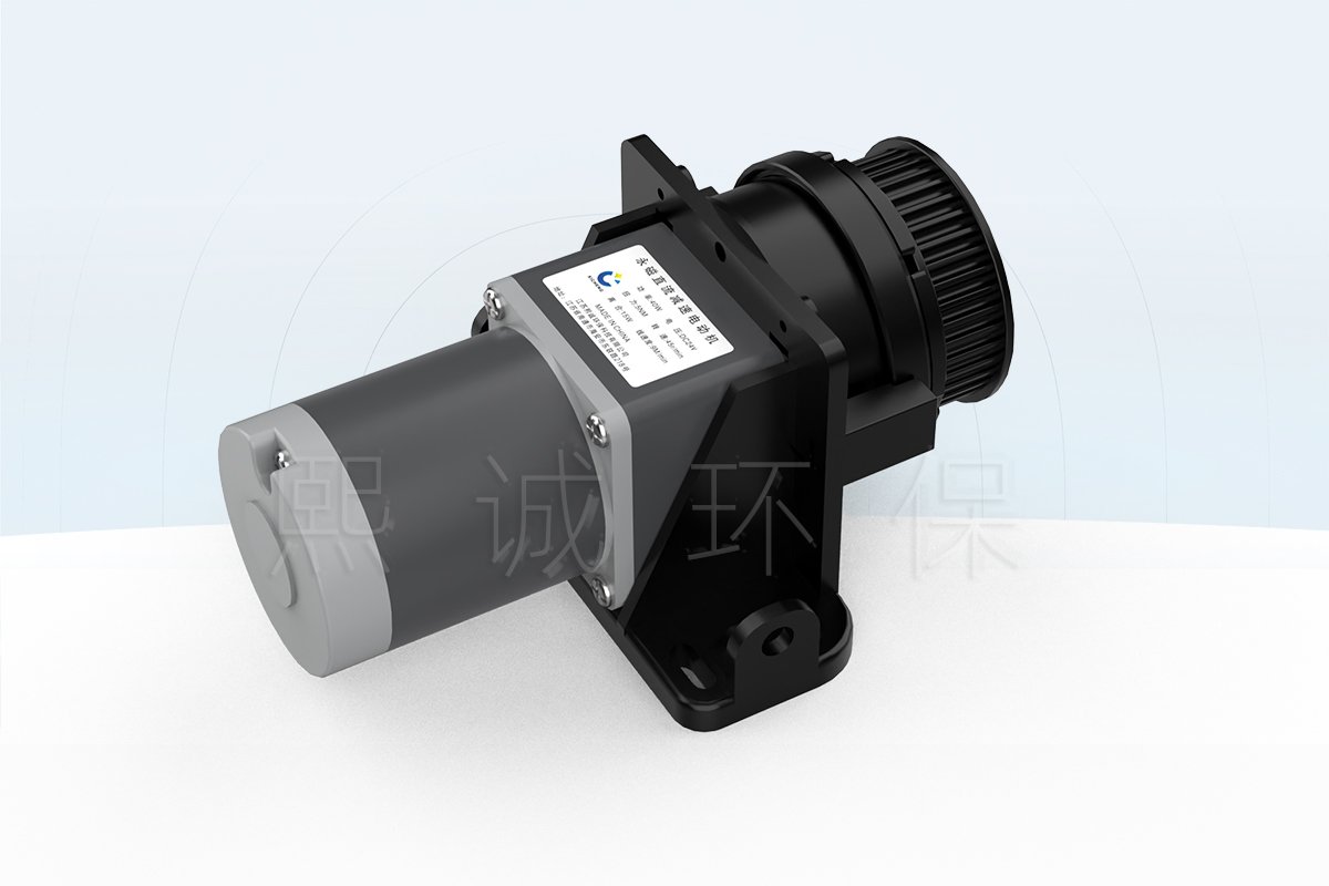
This automatic fume hood sash motor is the powered drive used to raise and lower a vertical sash. The 24 VDC gearmotor transfers rotary torque through the selected pulley, belt, cable or other sash transmission. A separate automatic sash controller commands direction and movement, while position and obstruction inputs tell the system where the sash is and whether motion may continue.
Choose This Drive Component When
Select this motor for a new automatic-sash assembly or a retrofit after checking the sash, counterbalance and transmission as one mechanical system. Hood width or glass weight alone is not enough for sizing. The remaining force after counterbalancing, the pulley or cable geometry and the controller’s stopping method determine whether the drive is suitable.
- A 24 VDC motor supply and compatible controller output are available.
- The 5 N m torque and 45 r/min output speed match the required transmission.
- The shaft, pulley, bracket and installation space can be matched from the hood drawing.
- The sash travel, balance condition, friction and required movement time are known.
- Position feedback and obstruction protection are included in the system design.
Core Drive Specifications
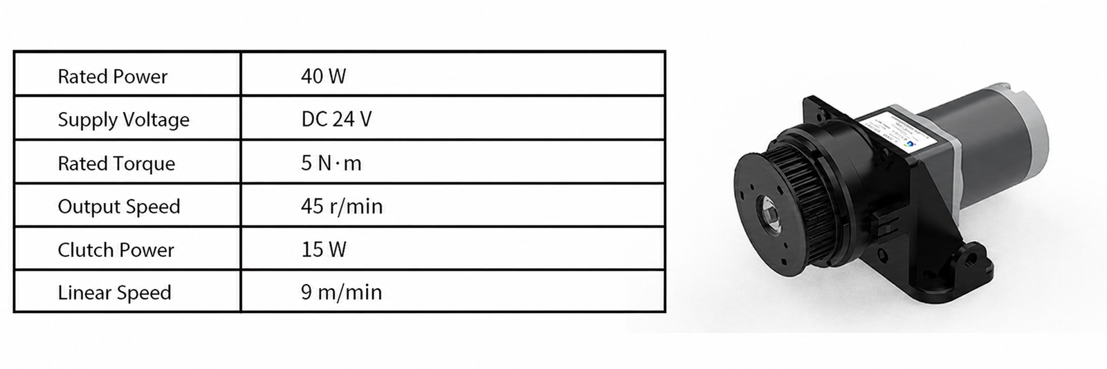
The motor operates on DC 24 V with 40 W rated power, 5 N m torque, 45 r/min output speed and a 9 m/min linear-speed reference. The drive also includes a clutch rated at 15 W. These values support initial selection, while the sash balance and transmission geometry determine the allowable moving load and final travel speed.
What the Motor Does Not Include
The sash drive motor does not decide when to open or close the window. It does not detect a person, identify an obstruction, measure sash position or regulate fume hood exhaust airflow. Those tasks belong to the automatic sash controller, occupancy and safety sensors, position feedback and ventilation-control equipment.
The motor is supplied as one component of the automatic-sash assembly. The quotation identifies whether the bracket, drive pulley, belt or cable parts, fasteners and wiring are included. The sash controller, position sensors and safety sensors are listed separately unless the order covers a complete system package.
Key Motor and Clutch Specifications
The specifications below describe the motor and clutch. Match them with the hood’s sash load, counterbalance, transmission, shaft and mounting space before ordering. Because sash mechanisms differ between hood designs, XICHENG confirms the output-shaft and mounting details against the customer’s drawing.
| Specification | Product Data |
|---|---|
| Product role | Automatic fume hood sash drive motor with clutch structure |
| Supply voltage | DC 24 V |
| Rated motor power | 40 W |
| Rated torque | 5 N m |
| Output speed | 45 r/min |
| Linear speed | 9 m/min reference |
| Clutch | Integrated clutch structure |
| Clutch power | 15 W |
| Shaft and mounting interface | Configured to match the sash transmission drawing |
| Sash load and travel | Selected from the sash balance, friction, transmission and travel data |
How to Interpret Torque and Speed
The 5 N m rating is rotary torque at the motor output. The force applied to the sash depends on the effective radius of the pulley or drive wheel and on losses in the belt, cable, bearings and guides. A smaller effective radius increases linear force but changes travel per revolution; a larger radius changes both force and speed. Use the complete transmission geometry instead of converting torque directly into a maximum sash weight.
The 45 r/min output speed and 9 m/min linear-speed reference do not automatically equal the installed sash speed. Pulley circumference, transmission ratio and controller acceleration or deceleration determine the actual motion. The drive can operate below its maximum reference speed when smoother starting, shorter stopping distance or quieter movement is required.
Mechanical Interfaces to Confirm
Provide the output-shaft diameter and profile, pulley or coupling interface, mounting-hole pattern, available envelope, cable direction and installation orientation. XICHENG uses these details to configure the drive and state which bracket, pulley and fasteners are included. For a replacement motor, measured dimensions and connector information are more reliable than a housing photograph alone.
Motor, Clutch and Sash Transmission
The sash drive converts the motor’s rotary output into controlled vertical travel. Compatibility is established across the complete path: gearmotor, clutch, output shaft, pulley or coupling, belt/cable mechanism, sash frame, guides and counterbalance. A mismatch at any point can produce slip, binding, uneven travel or excessive stopping distance even when the motor’s electrical ratings appear suitable.
Drive Path from Motor to Sash
The compact gearmotor uses a front drive assembly and mounting bracket. It can connect to a timing pulley, cable, chain or another matched sash transmission. The effective drive radius and transmission ratio determine how 45 r/min becomes linear sash movement. Correct alignment keeps the transmitted force centered instead of loading the shaft, bracket or sash guide sideways.
For a twin-sided sash suspension, confirm how both sides remain synchronized. One side must not lead the other and rack the sash in its guides. Where a timing-belt pulley assembly is used, match tooth profile, pitch, width, bore and shaft retention. Where a cable system is used, confirm drum or pulley diameter, cable path, anchoring and minimum bend conditions.
Purpose and Limits of the Clutch
The clutch allows the motor and sash transmission to engage or disengage according to the selected control arrangement. This can support manual movement or service recovery when the controller and mechanical design are configured for that function. The operating sequence and manual-release method are supplied with the matched controller and motor configuration.
The 15 W value describes clutch power; it is not a clutch torque or anti-pinch threshold. Obstruction protection therefore uses the specified safety sensor and controller response rather than an assumed clutch-release force. The installed system is tested with the actual sash before handover.
Mechanical Compatibility Checks
Confirm shaft fit, axial retention and bracket stiffness before the motor is mounted. The bracket must carry starting and reversing loads without shifting. The pulley or coupling must seat fully on the intended shaft feature and retain its alignment through repeated cycles. Guards and service panels must not contact the moving transmission.
Maintain access to the clutch, fasteners and electrical connection after the hood fascia is complete. For retrofit work, compare the available overhead or side-chase space with the full motor and transmission envelope. A drive unit that fits on a workbench may be impossible to service once it is installed behind a counterweight or fixed liner.
Matching the Motor to the Fume Hood Sash
Motor selection starts with the force required to move the actual sash, not with total glass mass alone. A properly counterbalanced sash may require only enough drive to overcome friction and a controlled residual imbalance. A poorly balanced or misaligned sash can demand much more force and can overload the transmission even when its nominal size resembles a previous installation.
Balance, Friction and Required Drive Force
Measure or calculate the moving sash mass, counterweight or spring assistance, residual unbalanced force and guide friction through the full travel. Check startup, mid-travel and both end regions because friction can change near seals, pulleys or guide transitions. Include the effect of attached handles, frames, cables and any horizontal sash elements moved by the same mechanism.
The motor’s 5 N m torque is matched after the effective drive radius and transmission efficiency are known. A stronger motor should not be used to compensate for a binding sash. Correcting the guide, balance or transmission condition first keeps manual operation, clutch behavior and stopping performance predictable.
Travel, Speed and Motion Profile
Define the closed position, normal working height, maximum opening and total travel. The required opening and closing time determines the target average linear speed. Compare that target with the 9 m/min drive reference and the selected pulley geometry. Acceleration and deceleration settings can prevent abrupt starting or full-speed contact with a travel limit.
Stopping distance is checked together with position feedback and obstruction detection. A higher travel speed reduces cycle time but leaves less distance for the safety input and controller to stop or reverse movement. The final motion profile is tested with the installed sash, guides and transmission.
New Hood Versus Retrofit Selection
On a new hood, the motor bracket, transmission and sensor locations can be coordinated before fabrication, leaving the required service access around the drive. For a retrofit, record the existing counterweight, cable or chain route, pulley dimensions, free space and manual operating force. Retaining a properly functioning balance system reduces motor load and preserves manual sash behavior.
The retrofit design also needs a manual recovery method for power loss or service. The clutch can provide a disengagement path when it is configured for that purpose. XICHENG supplies the applicable release procedure with the selected motor and controller arrangement.
Electrical and Automatic-Sash Control Integration
The 24 VDC motor operates as part of a controlled movement sequence. The controller switches the motor and clutch circuits, interprets position and safety inputs and applies the travel limits. The motor itself does not know the sash position or whether the closing path is clear.
Power and Direction Control
Match the controller output and DC power supply to the 40 W motor and clutch circuit for starting, running, reversing and holding conditions. The order-specific electrical drawing provides current, polarity, conductor protection and terminal assignments. Motors with the same voltage can use different connectors or control arrangements, so the supplied pinout is used for installation.
The control sequence defines opening, closing, stop and fault behavior. Check direction during setup before allowing full sash travel. Label both cable ends and record the final wiring arrangement, particularly where the controller reverses polarity or uses separate direction outputs.
Position Feedback and Travel Limits
An automatic fume hood sash controller requires reliable position information to stop at the closed, working and maximum-open points. The system can use a draw-wire sash position sensor that follows linear travel or a rotary position sensor coupled to pulley movement. Select the feedback method that matches the sash mechanism and calibrate its full usable travel.
Mechanical end stops should not be used as routine motor limits. The controller must slow or stop movement before the sash reaches a hard obstruction. After limit setup, repeat several complete cycles and confirm that the reported position remains consistent and that the transmission does not slip relative to the feedback device.
Occupancy and Obstruction Protection
Occupancy sensing can request automatic closing after the user leaves, while an infrared safety sensor protects the descending path. These are separate functions. A person-detection input does not prove that the opening is clear, and the motor clutch does not replace the anti-pinch sequence.
During commissioning, initiate an automatic closing cycle, interrupt the path with the specified test object and verify the required stop or reverse response. The same test confirms the controller state and manual recovery method during a sensor or communication fault. This proves the complete movement chain rather than only the motor direction.
Installation and Motor Selection
Correct installation combines the motor data with the hood’s mechanical and control details. Planning the bracket, shaft, transmission and service space before assembly keeps the drive aligned and accessible without restricting manual sash operation.
Mechanical Installation Checks
Before mounting, verify the bracket location, fastener support, output-shaft alignment and clearance through the entire transmission path. The bracket must sit on a structure capable of carrying motor reaction torque and repeated reversing loads. Align the pulley, belt, cable or coupling without pulling the motor shaft sideways. Fit any required guard while retaining access for inspection and clutch service.
Cycle the sash manually before coupling the motor. It should move smoothly through the intended travel without binding, unexpected weight change or contact with the hood liner. After coupling, begin at reduced or controlled movement where the system permits, verify direction and limits, then complete the operating and safety tests.
Confirm the Supplied Scope
Choose whether the order includes only the motor or also the mounting bracket, drive pulley, belt or cable parts, clutch connection, controller cable and fasteners. The related automatic sash drive pulley is a separate transmission component unless it is included in the selected package. The FSC10 controller, position sensors, occupancy sensor and anti-pinch sensor are also available as separate system components.
For a replacement, provide photographs of the installed motor label, shaft, pulley, bracket and connector together with measured dimensions. A visual match of the housing is insufficient if the shaft profile, mounting holes, clutch wiring or rotation direction differs.
Information Required for a Quotation
Send the hood model or drawing, sash type, moving mass, counterbalance arrangement, residual manual force, total travel, required opening and closing time, transmission drawing, effective pulley radius, output-shaft requirement, available space, 24 VDC power source, controller model, position-feedback method, safety inputs, quantity and destination.
XICHENG uses these inputs to match the 40 W, 5 N m motor with the sash mechanism and electrical controls. The quotation identifies the motor, clutch, bracket and transmission parts included in the supply, followed by a drawing for the shaft, mounting and connection details that apply to the selected configuration.
Frequently Asked Questions
Is this motor a complete automatic sash system?
No. It is the mechanical drive component. A complete system also requires a compatible controller, position feedback, safety inputs, transmission components, power supply and an approved control sequence.
Can 5 N m torque be converted directly into a maximum sash weight?
No. Linear force depends on the effective pulley radius, transmission losses, sash balance and guide friction. Provide the counterbalance and transmission data so the motor can be checked against the actual moving load.
Does the 9 m/min value equal the final sash speed?
It is the linear-speed reference for the drive. Final sash speed depends on pulley or cable geometry, transmission ratio and controller motion settings, and is verified on the installed hood.
What is the purpose of the clutch?
The motor includes a clutch rated at 15 W. The selected controller and drive arrangement determine how the clutch engages, releases and supports manual operation; 15 W is a power value, not an anti-pinch threshold.
Can it replace an existing sash motor?
Replacement is possible only after the supply, shaft, mounting holes, pulley or coupling, direction, controller interface, travel, balance and safety sequence are compared. Provide the existing label, dimensions and wiring information.
Which safety devices are required?
The motor does not determine the safety sequence. Automatic closing uses position feedback and obstruction protection, while occupancy sensing can initiate the closing request. The controller coordinates these inputs and the motor response.
Contact the Xicheng Engineering Team Today
Send the sash drawing, travel, moving mass, counterbalance details, manual operating force, transmission layout, required movement time, controller and 24 VDC supply information. XICHENG will match the motor, clutch, mounting and transmission interface and provide a configuration drawing and quotation.
Shenzhen Office: No. 34 Zhenxing Road (Shengtaian Heavy Industrial Park B), Loucun, Guangming New Dist, Shenzhen, Guangdong, China
WhatsApp: +86 18126478161
Engineering Mailbox: fanalax34@gmail.com