


Description
Rotary Position Sensor for Fume Hood Sash Feedback
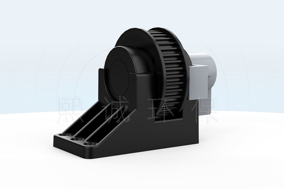
This rotary position sensor measures fume hood sash movement through a timing-pulley coupling. As the sash drive belt moves, the 5M40 pulley turns the shaft of a precision sliding potentiometer. The resulting 0-10 kOhm resistance change gives a compatible controller a repeatable position reference for open, intermediate and closed sash positions.
Choose the Rotary Arrangement When
The pulley-coupled arrangement is suited to automatic sash systems in which the timing belt already provides a stable mechanical reference. It avoids routing a separate draw wire across the full sash travel and keeps the sensing mechanism close to the drive assembly. The selected pulley, belt pitch, shaft alignment and controller input must be treated as one system.
- The sash mechanism uses a compatible 5M timing belt and M40 pulley geometry.
- A 0-10 kOhm three-wire potentiometer input is available at the controller.
- The mounting structure can hold the sensor shaft concentric with the pulley.
- Closed and open positions can be calibrated after the sash mechanism is commissioned.
- The potentiometer can remain inside its electrical rotation throughout full sash travel.
Key Product-Family Data
The sensor has a flame-retardant ABS enclosure. Its standard timing pulley and mounting bracket use PP reinforced with 30% glass fiber for corrosion resistance around laboratory equipment. Measurement error is within 2%. A 0.3 mm2 three-core shielded signal cable is supplied at a standard length of 1.5 m to reduce interference between the position sensor and controller.
Position Feedback, Not Standalone Control
The potentiometer position sensor reports mechanical position only. It does not move the sash, detect personnel, provide anti-pinch protection or measure face velocity. An automatic fume hood sash controller interprets the resistance signal as part of a complete operating sequence. A separate airflow-control system remains responsible for ventilation performance.
Key Specifications and Supplied Interface
The values below describe the XICHENG rotary sash-feedback assembly. Confirm pulley position, bracket arrangement and controller input before ordering because the same resistance sensor can produce an incorrect position indication if its mechanical travel is mismatched to the sash drive.
| Selection Item | Available Product Data |
|---|---|
| Sensor type | Rotary sliding-potentiometer position sensor |
| Resistance range | 0-10 kOhm |
| Measurement error | Within 2% |
| Enclosure | Flame-retardant ABS |
| Pulley and bracket | PP + 30% glass fiber |
| Standard pulley | 5M40 timing pulley |
| Signal cable | 0.3 mm2, three-core shielded, 1.5 m standard length |
| Adjustable mounting height | 90.7-212.7 mm for the illustrated wheel-mount arrangement |
| Connection | Three-wire potentiometer: red, white wiper and yellow |
Items to Confirm with the Sash Mechanism
Check the belt pitch, pulley tooth count, sash stroke, counterweight path and available mounting plane. The resistance range alone does not determine compatibility. The mechanical ratio must rotate the potentiometer through a useful part of its range without reaching either stop during normal or service movement.
The illustrated 5M40 pulley identifies a 5 mm belt pitch and a 40-tooth pulley arrangement. Confirm that the installed belt profile and tooth geometry match; a pulley that looks similar can still engage incorrectly. Also check whether one pulley revolution corresponds directly to sash movement or passes through another drive ratio. That relationship determines how much resistance change is available between closed and open positions.
Values Not Defined by This Sensor
Controller supply voltage, airflow setpoint, alarm threshold, fail-safe sequence and motor torque are not properties of the passive potentiometer. They belong to the controller, sash motor and project control design. IP rating, ambient-temperature range and cycle life are not stated for this sensor and should be confirmed when a project requires those values.
The within-2% measurement error describes the sensor measurement performance, not the accuracy of a complete face-velocity or sash-height display. Belt stretch, pulley slip, bracket movement, controller analog resolution and calibration-point quality can add system-level error. Project acceptance should therefore compare the indicated position with physical sash positions after the complete mechanism is installed.
How Rotary Sash Position Measurement Works
The timing belt translates sash movement into pulley rotation. Two threaded holes on the sensor body secure it to the matching pulley assembly, allowing the pulley shaft to turn the sliding potentiometer. The controller reads the resistance between the wiper and an end terminal and maps that value to a calibrated sash opening.
Set the Mechanical Zero Before Final Coupling
Move the sash to the chosen reference position, then set the potentiometer to zero or the required starting resistance before tightening the coupling. This step preserves usable electrical travel in both directions. Rotating the pulley first and attempting to correct the range only in software can leave the sensor too close to an end stop.
Calibrate Closed and Open Positions
After installation, record the stable resistance at the fully closed position and at the permitted maximum opening. Check at least one intermediate position to confirm that belt motion, pulley rotation and resistance change remain consistent. The controller can then scale the signal to sash height or opening percentage.
Repeat the check while moving in both directions. A meaningful difference between the opening and closing readings at the same physical point can indicate belt backlash, a loose shaft connection or movement in the mounting bracket. Correct the mechanical cause before compensating in controller software. Finally, confirm that the signal direction agrees with the control sequence: opening the sash should consistently produce the configured increase or decrease in the displayed position.
Keep Position and Airflow Verification Separate
Sash position can be used to calculate an airflow demand, but it is not a direct air-velocity measurement. A VAV sequence may use the position signal to command an exhaust valve while an independent airflow or face-velocity sensor verifies actual performance. This distinction prevents belt slip, a loose coupling or a calibration error from being mistaken for confirmed containment.
For automatic sash operation, the controller can also use the calibrated position to stop at defined open and closed limits. That does not remove the need for obstruction protection. A dedicated infrared or contact safety input should interrupt closing when an object is detected, while the rotary sensor continues to report where the sash is located.
Fixed Pulley-Mount Dimensions
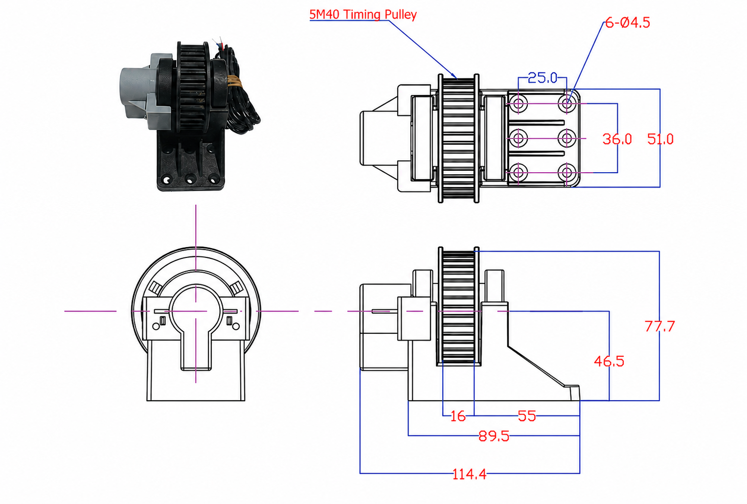
The compact arrangement places the rotary potentiometer beside the 5M40 timing pulley and fixes the support through six 4.5 mm holes. The illustrated envelope is 114.4 mm long and 77.7 mm high, with a 55 mm base section. Use the drawing to reserve space for the sensor body, pulley, cable exit and fasteners.
Alignment Conditions
Mount the bracket on a rigid plane and align the sensor shaft with the pulley axis before tightening the fasteners. Angular or lateral misalignment can create side load, uneven rotation and a shifting resistance signal. The belt should track centrally without rubbing the pulley flange or pulling the sensor bracket out of position.
Service Clearance
Leave access to the cable termination, mounting screws and pulley coupling. The sensor may need to be re-zeroed after belt replacement, pulley removal or major sash adjustment. A concealed installation that cannot be reached without dismantling the hood increases commissioning and maintenance time.
Before closing the service panel, mark the calibrated pulley and shaft relationship or record reference resistance values. During maintenance, these references make it easier to identify an unintentionally shifted coupling. Do not lubricate the timing-belt teeth or potentiometer shaft unless the supplied component instructions specifically permit it; lubricant can attract contamination or change belt engagement.
Height-Adjustable Wheel-Mount Arrangement
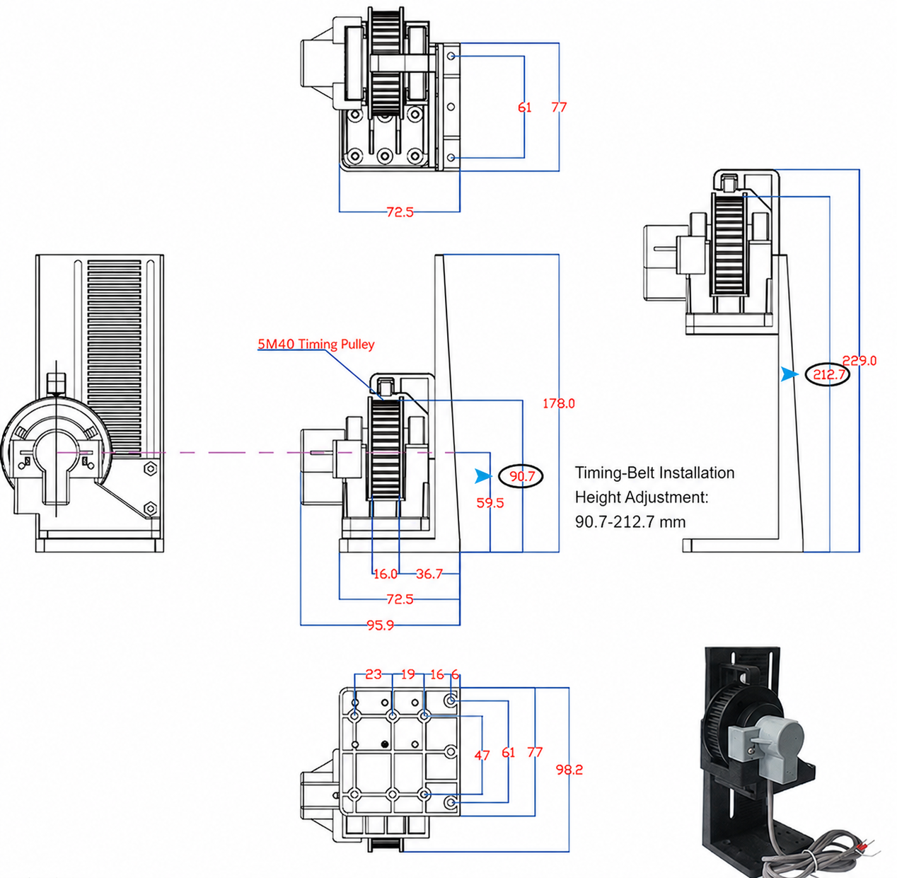
The wheel-style bracket provides a larger mechanical envelope and allows timing-belt installation height to be adjusted from 90.7 to 212.7 mm. This option is useful when the sash frame, counterweight path or enclosure geometry prevents a compact fixed mounting position.
Select the Bracket from the Actual Hood Layout
Compare the drawing with the sash frame and drive layout, not only with the nominal hood width. The adjustable assembly reaches approximately 229 mm in the illustrated upper position and has a 95.9 mm lower base envelope. Confirm that the full adjustment path remains clear of panels, weights, wiring and service covers.
Commission the Complete Transmission
Cycle the sash slowly by hand before energizing the automatic drive. Watch the belt engagement, pulley rotation and resistance reading together. Then operate the sash under controller command and verify that no belt slip or bracket movement occurs during acceleration, reversal or stopping.
Acceptance should include repeated full travel, intermediate stops and a power-cycle check. The controller should recover the same displayed position after power returns without requiring the sash to move beyond its normal limits. If the reading changes while the sash remains stationary, inspect terminals, shielding, coupling security and belt tension before replacing the sensor.
Typical Fault Indicators
A fixed reading across the full sash travel usually points to an open circuit, incorrect terminal selection or a coupling that is not turning the potentiometer. A sudden jump suggests an intermittent connection or mechanical slip. A smooth but incorrectly scaled reading generally requires calibration or a mechanical-ratio review. A reading that reaches its limit before the sash reaches full travel indicates that the initial potentiometer position or pulley ratio must be corrected.
Wiring and Controller Integration
The sensor uses a three-wire potentiometer circuit. Terminal 1 is red, terminal 2 is the white wiper lead and terminal 3 is yellow. Connect the end terminals and wiper according to the controller input diagram; do not infer signal direction from color alone because increasing resistance can be assigned to opening or closing during commissioning.
Shielded Signal-Cable Practice
Route the 1.5 m shielded cable away from sash-motor power wiring and switching loads. Avoid sharp bends and provide strain relief where the cable enters the control enclosure. If the cable must be extended, preserve the three conductors and shielding method required by the controller and verify the resistance reading after termination.
Check resistance with the sensor disconnected from the controller before first power-up. Measure between the two end leads to confirm the full potentiometer value, then measure from the white wiper to each end while the pulley moves. The two partial readings should change in opposite directions. This simple check catches wiring errors without applying an external voltage to the passive sensor.
Product Selection Summary
Choose Rotary or Draw-Wire Feedback
Choose this rotary position sensor when the sash mechanism provides a stable timing-pulley interface and compact local feedback is preferred. Choose the string potentiometer sash position sensor when a protected straight cable can directly follow sash travel and no pulley-shaft coupling is available.
Information Required for Selection
Provide the sash type and stroke, belt pitch, pulley geometry, mounting drawing, available installation height, controller make and potentiometer-input range, desired signal direction and cable-routing distance. State whether the sensor is for position display, automatic sash control or a VAV command sequence. These details determine the mounting arrangement and calibration method.
For replacement work, include photographs of the existing pulley, sensor mount and terminals, plus measured resistance at closed and open positions when available. For a new hood, provide the mechanical elevation showing the sash, counterweight, belt path and service-panel clearance. These records help distinguish a direct replacement from a bracket or pulley adaptation.
Related Automatic Sash Components
The sensor can work with an automatic fume hood sash motor and an automatic sash drive pulley. Mechanical compatibility must be checked across the belt, pulley, motor, bracket and sash travel rather than selecting each component independently.
Also confirm that the controller has a dedicated potentiometer input and a commissioning routine for assigning closed and open values. A generic analog voltage input is not automatically compatible with a passive resistance sensor.
Frequently Asked Questions
Does the rotary position sensor measure face velocity?
No. It measures pulley rotation as a proxy for sash position. Face velocity requires an airflow or velocity sensor and separate commissioning.
What output does the sensor provide?
It provides a three-wire 0-10 kOhm potentiometer signal. The controller scales resistance to sash position during calibration.
Why must the sensor be zeroed before installation?
Zeroing or setting the starting resistance places the required sash travel inside the potentiometer’s usable rotation and reduces the risk of reaching an electrical end stop.
Can it replace a draw-wire sash sensor?
Only when the sash mechanism has a compatible pulley coupling and the controller accepts the same signal type. The two products use different mechanical interfaces.
What does the 90.7-212.7 mm range mean?
It is the timing-belt installation-height adjustment shown for the wheel-style bracket. It is not the sash stroke or sensor electrical range.
Is the position signal an anti-pinch input?
No. Position feedback and obstruction detection serve different functions. Use a dedicated sash safety sensor for anti-pinch protection.
What should be checked during routine maintenance?
Check belt condition and tension, pulley alignment, bracket security, cable terminals and repeatability at known sash positions. Recalibrate after changes to the sash drive or sensor coupling.
Contact the Xicheng Engineering Team Today
Send the sash travel, timing-belt and pulley details, mounting drawing, controller input specification and intended control sequence. XICHENG will review the mechanical interface, signal compatibility and installation arrangement and provide a product proposal and pricing within 24 hours.
Shenzhen Office: No. 34 Zhenxing Road (Shengtaian Heavy Industrial Park B), Loucun, Guangming New Dist, Shenzhen, Guangdong, China
WhatsApp: +86 18126478161
Engineering Mailbox: fanalax34@gmail.com