


Description
Fume Hood Control Power Box Overview
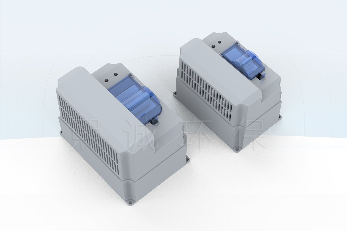
The XICHENG fume hood control power box provides a local power connection, circuit breaker and field terminal for laboratory ventilation controls. Its compact PC+ABS enclosure is used with fume hoods, VAV Venturi systems and variable-air-volume control equipment where the controller, actuator, lighting or related loads need an organized connection and protection point near the equipment.
A clear window shows the breaker position without removing the cover, while the widened handle provides direct local operation. The green indication corresponds to OFF/open and the red indication to ON/closed. The box is configured for the actual incoming supply and connected loads rather than supplied as one universal voltage and current arrangement.
Choose This Control Power Box When
- A fume hood or laboratory airflow-control assembly needs a dedicated local breaker and terminal point.
- The controller, valve, actuator, fan interface or lighting loads have been identified.
- Field wiring needs a compact enclosure with visible breaker status and service access.
- The incoming supply, outgoing circuits and protective device can be selected from a load schedule.
- The box can be mounted away from direct chemical splash, condensate and obstructed maintenance areas.
Key Decisions Before Ordering
Start with the electrical loads, not the breaker shown in a reference photograph. Confirm the site voltage and frequency, the number and duty of connected circuits, normal and starting current, conductor sizes, grounding, local isolation and required protection. These inputs determine the breaker, terminal arrangement and internal wiring supplied with the box.
What the Power Box Does Not Replace
The enclosure does not measure face velocity, calculate airflow or command a valve by itself. Those functions belong to the connected monitor or controller. It also does not replace the building distribution board, upstream branch protection, emergency-power design or site lockout procedure unless those items are explicitly included in the electrical design.
Key Construction and Electrical Specifications
The control power box combines a PC+ABS enclosure, circuit breaker, field terminal and visible operating status. Electrical ratings are selected to match the connected laboratory equipment, allowing the same enclosure concept to support different fume hood and VAV control packages.
| Specification | Product Information |
|---|---|
| Product type | Control power connection and protection enclosure |
| Enclosure material | PC+ABS |
| Integrated component | Circuit breaker selected for the connected load schedule |
| Field connection | Large terminal interface for incoming and outgoing wiring |
| Breaker access | Widened operating handle with covered enclosure |
| Status viewing | Clear window for breaker-state inspection |
| Status indication | Green for OFF/open; red for ON/closed |
| Applications | Laboratory fume hoods, VAV Venturi systems and variable-air-volume control equipment |
Electrical Configuration Fields
| Selection Field | Information Needed |
|---|---|
| Incoming power | Voltage, frequency, conductors and grounding arrangement |
| Connected equipment | Controller, actuator, fan interface, lighting or other load and quantity |
| Load data | Continuous current, starting current and switching duty for each circuit |
| Circuit arrangement | Number of outgoing circuits and any required separation between different voltages or functions |
| Protection | Breaker current, trip curve, pole count and additional project-specific protection |
| Field wiring | Terminal assignment, conductor size, cable entry and external disconnect |
| Installation environment | Mounting position, temperature, moisture and possible chemical exposure |
Example Breaker Configuration
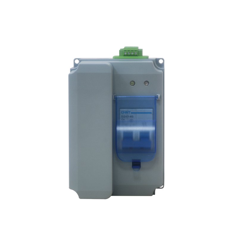
The visible C4 marking represents a 4 A C-curve breaker in this example. It is not the fixed rating for every control power box. The breaker and wiring must be selected from the voltage, load and fault-protection requirements of the equipment being connected.
Power Distribution, Protection and Operating Features
Incoming control power enters the enclosure and passes through the selected circuit breaker before reaching the field terminal and designated downstream circuit. This arrangement creates a local point for switching, protection and service isolation near the fume hood or airflow-control equipment. The exact internal path depends on the number of circuits and loads included in the order.
Role of the Circuit Breaker
The breaker disconnects the configured circuit and provides the protection associated with its current rating, trip curve and pole arrangement. Correct protection still depends on the conductor size, load current, starting characteristics, available fault level and upstream coordination. A breaker with the correct nominal current can still be unsuitable if its curve, poles or system voltage do not match the installation.
Where several devices are powered from one box, the electrical design should decide whether they share one circuit or require separate protection. A controller, actuator, lighting circuit and fan interface can have different voltages and switching duties and should not be grouped simply because they are installed on the same fume hood.
Visible ON/OFF Status
The clear viewing window allows the breaker position to be checked without removing the enclosure cover. Green indicates OFF/open and red indicates ON/closed. This visual indication supports routine operation and fault tracing, but maintenance personnel should still verify isolation with the required test procedure before working on downstream wiring.
Field Terminal and Cable Organization
The large terminal interface provides a defined point for incoming and outgoing conductors. Each circuit should be labelled by function and destination so a controller supply is not confused with an actuator, lighting or fan-interface circuit. Cable entries should provide strain relief and keep power wiring separated from low-level sensor or communication wiring where required.
PC+ABS Enclosure and Application Environment
The PC+ABS housing encloses the breaker and wiring connections in a compact assembly. Mount it in a dry, accessible location protected from direct chemical splash, condensate and mechanical impact. Where the box will be exposed to washdown, corrosive vapor or outdoor conditions, specify the environmental requirement before ordering so the enclosure and installation method can be reviewed for that location.
Installation, Field Wiring and Maintenance Access
Install the fume hood control power box where the breaker handle, viewing window and terminal remain accessible after the hood panels, ductwork and control devices are fitted. The mounting surface should support the enclosure and cable load without distortion, and the cable entries should not face a direct source of liquid or corrosive residue.
Check Supply and Loads Before Wiring
Compare the product wiring information with the site supply and every connected device. Verify voltage, frequency, grounding, circuit assignment, continuous current, starting current and conductor size. If the installed breaker or terminal arrangement does not match the load schedule, correct the configuration before power is applied.
Separate and Label the Circuits
Route incoming power and outgoing load conductors so they do not place strain on the terminal or breaker. Maintain the required separation from communication, sensor and analog signal cables. Label both ends of each cable and identify the controlled equipment, protective device and terminal number on the project drawing.
Provide Safe Service Access
Leave enough clearance to operate the breaker, open the enclosure where required and retighten or replace terminal connections. The box should not be hidden behind a fixed duct, counterweight or panel that must be dismantled for routine inspection. External isolation and lockout provisions remain accessible to maintenance personnel.
Commissioning Checks
After wiring inspection, verify protective-earth continuity, breaker OFF/ON indication, downstream voltage and the response of each connected device. Check that conductor insulation is not trapped, terminals remain secure and cables do not move when the hood or sash operates. Record the installed breaker and circuit assignments for future replacement and troubleshooting.
Applications, System Fit and RFQ Information
The fume hood control power box is used where laboratory ventilation equipment needs a compact local power and protection point. Typical applications include fume hood controllers, VAV Venturi equipment, airflow-control valves, damper actuators, control panels and selected fan or lighting interfaces. The connected load list determines whether one circuit is sufficient or a multi-circuit arrangement is required.
Select the Box from the Load Schedule
List every device that will receive power through the box and separate devices with different voltages or switching duties. Include normal current, starting current and any requirement for individual isolation. This prevents a low-power controller circuit from being sized or protected as though it were a motor or lighting circuit.
Coordinate with Fume Hood Controls
The power box can supply an automatic fume hood sash controller, a fume hood airflow monitor, a fume hood controller, or related airflow-control equipment when their voltage and current requirements match the selected configuration. It provides power distribution and local protection; the connected device still performs the monitoring, control or actuator function.
Confirm the Supplied Scope
State whether the order requires the enclosure and breaker only or a completed assembly with terminals, internal wiring, cable entries, labels and connectors. Also identify any mating cables, mounting hardware or external disconnect that must be included. Clear supply boundaries make installation faster and avoid duplicate or missing protective devices.
Information Needed for a Quotation
Send the site supply, connected-device list, current and starting-load data, required circuit arrangement, protection requirements, conductor sizes, cable-entry direction, mounting location, environmental conditions, quantity and destination. Include the single-line diagram or control schematic when available.
XICHENG will configure the enclosure, breaker, terminal and internal circuit arrangement for the stated loads and provide the applicable connection information with the quotation.
Frequently Asked Questions
Is this a fixed-output fume hood power supply?
No. It is a configurable power connection and protection enclosure. Its supply, outgoing circuits, breaker and terminals are selected for the equipment connected to it.
What equipment can the control power box support?
It can be configured for fume hood controllers, airflow monitors, VAV equipment, actuators and selected fan or lighting interfaces. Compatibility depends on the voltage, current, circuit and protection requirements of each load.
Is a CHINT DZ47-60 C4 breaker standard on every box?
No. A 4 A C-curve breaker is shown in one example configuration. The breaker current, curve and poles are selected from the connected-load and site-protection requirements.
Can several loads share one breaker?
Only when their voltage, current, switching duty and protection requirements allow a common circuit. Devices with different supplies or critical functions may need separate circuits and terminals.
Does the power box control airflow?
No. It provides the configured electrical connection and protection. Airflow measurement and regulation require the appropriate sensor, monitor, controller and valve or damper.
Where should the box be installed?
Mount it in an accessible, dry location near the controlled equipment, with space for breaker operation, terminal service and cable routing. Avoid direct chemical splash and condensate unless the specified enclosure is suitable for that exposure.
What information is needed for a replacement?
Provide the existing supply, breaker marking, terminal and circuit arrangement, connected loads, enclosure photographs and mounting dimensions. Do not select a replacement from the external enclosure alone.
Contact the Xicheng Engineering Team Today
Send the site supply, connected-load list, circuit and protection requirements, conductor sizes, mounting conditions and control schematic. XICHENG will configure the breaker, terminal, enclosure and wiring arrangement for the selected laboratory control equipment.
Shenzhen Office: No. 34 Zhenxing Road (Shengtaian Heavy Industrial Park B), Loucun, Guangming New Dist, Shenzhen, Guangdong, China
WhatsApp: +86 18126478161
Engineering Mailbox: fanalax34@gmail.com