


Key Specifications and First Selection
A modular laboratory workstation is planned as a system rather than as an isolated table. Its useful feature is not simply that shelves or drawers can be ordered separately. A compatible base frame, uprights, attachment points, service route and end conditions allow selected components to be installed, moved or expanded without replacing the complete underlying structure. That distinction matters when a laboratory expects equipment, personnel count, storage needs or utility requirements to change over time.
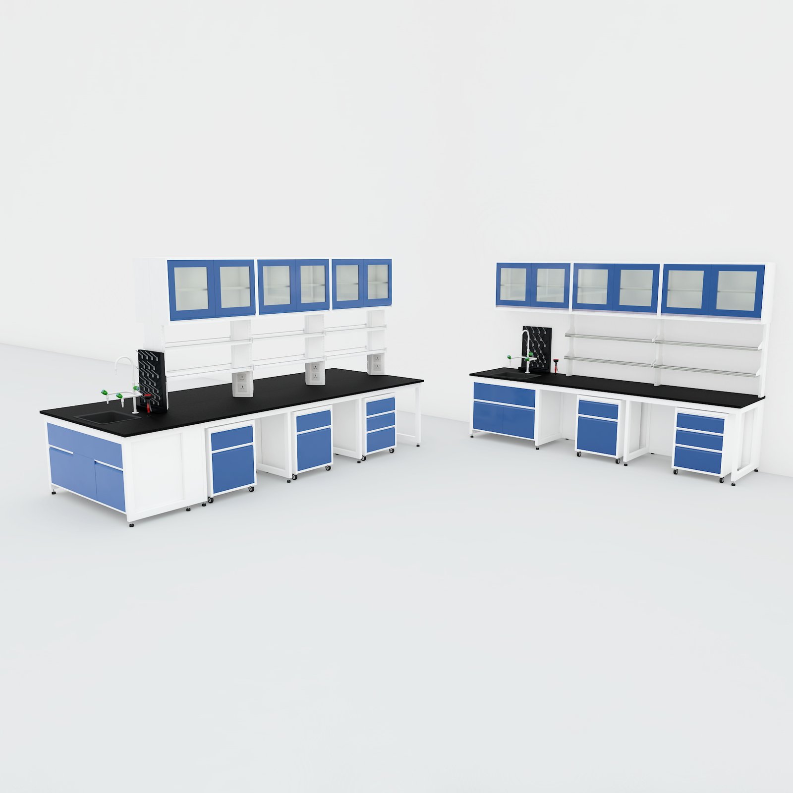
A modular lab bench can be configured as a wall-side single-sided station, a double-sided central arrangement, a linked row, an end module or a compact equipment station. The selected configuration must identify one frame family before its dimensions, worktop, storage and load fields are used. A 1200 lb published total distributed reference for one single- or double-sided frame system, a 150 or 200 kg/m2 reference for another frame system, and a mobile caster rating are different conditions. They cannot be combined into one universal specification.
| First selection field | Decision required | Why it changes the workstation | Information to confirm before release |
|---|---|---|---|
| Base layout | Wall-side, double-sided, end, continuous run or mobile module | Determines access, support, service path and future expansion direction | Room plan, operator sides, aisle clearance and module sequence |
| Interface system | Uprights, rails, hooks, service spine or framed attachment points | Defines which shelves, storage and service modules can be repositioned | Compatible interface, fasteners, tools and permitted attachment loads |
| Equipment load | Distributed surface load, local equipment bases, shelves and cabinets | Changes frame, worktop support, stability and moving-component limits | Equipment schedule, centres of gravity and each component load |
| Utility scope | Power, data, gas, vacuum, water or drainage | Determines service core capacity, access, isolation and commissioning steps | Connection type, location, local code requirements and spare capacity |
Start with the change that the laboratory expects
The first planning question is what will change after installation. A project that only expects to add an under-bench drawer or shelf needs a different interface strategy from a laboratory that expects to rearrange instrument positions, add a second operator side, extend a bench run or reroute power and data. Water, gases, vacuum and electrical circuits require their own controlled connection and test procedures. A movable shelf does not mean a utility connection can be moved without isolation, qualified reconnection and functional checks.
Reference dimensions and configuration families
Published modular workstation families illustrate several separate planning ranges. One single-sided frame family uses 36, 48, 60 or 72 in widths, 30 or 36 in depths and a 30.75-36.75 in six-position work-height range. A matching double-sided family uses a 60 in overall depth with separate rear upright structure. Other modular systems use 900, 1200, 1500 or 1800 mm widths, 750 or 900 mm depths and 750 or 900 mm working heights. These values help frame an early room layout; the final quotation must select one compatible geometry rather than combining the most favorable number from several systems.
What the opening specification does not decide
The opening table is not a substitute for a released engineering layout. Worktop chemistry, thickness and cut-outs; shelf or suspended-cabinet loads; the location of every equipment foot; utility connections; wall and floor conditions; and the exact reconfiguration method remain project-specific. A modular laboratory bench also does not replace a dedicated mobile laboratory bench where frequent transport is the primary requirement, an adjustable height lab bench where continuous ergonomic lift is required, or a laboratory island bench where the principal decision is a fixed central island layout.
What Makes a Laboratory Workstation Modular
Modularity is established by repeatable interfaces that accept planned components. Depending on the selected system, those interfaces may include upright frames, horizontal rails, slot or hook positions, service spines, framed openings, standardized bay widths or attachment hardware. The frame should retain its required load path and stability after a permitted shelf, cabinet, task light or service module is added. A worktop with custom dimensions alone is not proof of a reconfigurable laboratory workstation.
Reconfiguration is controlled work
Before a module is moved, record the current arrangement, remove or support affected equipment, isolate any connected services, and check that remaining frame members retain the required support and anti-tip condition. After the new arrangement is assembled, check fasteners, level, worktop joints, attachment engagement, equipment clearances and any altered service route. Electrical, water, gas and vacuum changes should be reconnected and tested through the required site process rather than treated as a furniture-only adjustment.
Boundaries on compatibility
Attachment geometry, hole positions, hooks, rail profiles and service modules are normally specific to one system. Cross-brand interchangeability should not be assumed from a similar visual appearance. The final order should list the base frame, upright profile, bay width, hardware, shelf type, cabinet type and utility modules together. This protects a future expansion from becoming a mixture of parts that cannot safely connect or carry the intended load.
Planning expansion at the first installation
An extension can require more than an open floor area. Allow for terminal legs, end panels, frame joining hardware, service capacity, cable length, worktop seam treatment, leveling positions and an accessible route for installation. A double-sided station also needs a separate review of each operating side. The total system load is not automatically a per-side capacity, and a central service core can change both the usable worktop depth and the maintenance path.
Configurations, Load Paths and Worktop Selection
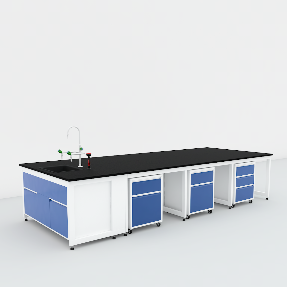
The frame layout should follow the work sequence. A single-sided modular lab bench keeps the operator and service face on one side and suits wall-side work or a narrow room. A double-sided arrangement supports two working faces but needs adequate central support, access from both sides and clear separation of the equipment and utility demands. Fixed feet generally suit a stable, planned workstation location. A caster configuration must use its own approved movement and parked-load conditions.
Configuration reference directions
Single-sided frame: One published frame family uses 36-72 in widths, 30 or 36 in depths, and a 30.75-36.75 in six-position working-height range. It is useful where wall-side access, under-bench clearance or a rear service zone is needed. The selected worktop, total frame load and shelf load still remain tied to that released version.
Double-sided frame: A separate family uses 36-72 in widths with 60 in total depth. It is intended for two operating faces and requires both sides to be scheduled for equipment, storage and utility outlets. Its total system capacity must not be represented as an independent capacity for each side.
Metric C-frame station: One modular C-frame family uses 900-1800 mm widths, 750 or 900 mm depths and 750 or 900 mm heights, with a published 150 kg/m2 reference. It favors open knee space and single-sided access; its load and fixed/mobile fields stay within that family.
Metric H-frame station: Another family uses the same broad metric geometry but a 200 kg/m2 published reference and a different frame arrangement. It may suit a more symmetrical equipment layout, but it must not inherit values from the C-frame configuration.
Separate the load questions
Total static evenly distributed load, a concentrated instrument footprint, an upper-shelf load, a suspended cabinet load, a mobile-cabinet load and a load while the unit is being moved are separate technical questions. An analytical instrument near one corner can cause a different frame condition from a lighter load distributed across the complete surface. The same applies to a sink opening, heavy monitor arm, gas cylinder restraint, raised enclosure or under-bench drawer bank. Record the mass, footprint, center of gravity, support feet and maintenance pull-out space for each major item.
Worktop selection follows the process
Phenolic, epoxy resin, stainless steel, ceramic and compact laminate worktops appear across laboratory furniture systems, but they do not have the same chemical, thermal, impact, seam and support behavior. A selected worktop should be reviewed against the actual reagents, cleaning process, temperature exposure, equipment foot pressure, required cut-outs and edge condition. Thickness and material add mass to the frame and can change the height of an upper shelf or service point. A worktop suitable on a fixed wall bench may need a different support pattern on a modular system with long spans or removable modules.
Storage must preserve the working envelope
Suspended cabinets protect floor clearance but reduce knee space and can change access to services. Mobile cabinets offer local storage but introduce caster clearance and parking requirements. Open shelves simplify frequent access but need containment, cleanability and item-height review. The selection should show which storage component occupies each bay, where it is attached, how it opens, and whether it remains in place after a future module extension.
Modularity versus a fixed casework run
A fixed laboratory wall bench can be more direct where a room layout, services and storage arrangement will remain unchanged for the long term. A modular laboratory workstation is more appropriate when the system has a defined and useful reconfiguration path. The decision is therefore not about which description sounds more flexible; it is about whether the expected change justifies the frame interfaces, service access and future configuration control.
Services, Storage and Controlled Reconfiguration
An integrated service route can keep electrical and data cables, gases, vacuum or water connections accessible while maintaining a clear work surface. It also introduces a boundary: furniture modules and utility modules must be planned together, but they do not have the same change procedure. The selected service spine, upright or side panel should have enough capacity for the initial layout and a documented allowance for future work. The location of isolation points, inspection access and labels must stay visible after storage and equipment are installed.
Utility routing by service type
| Service group | Planning fields | Change-control requirement | Final check |
|---|---|---|---|
| Power and data | Voltage, circuit, outlets, data type, separation, grounding and cable route | Isolate the circuit and update identifiers before a module position changes | Protection, polarity, grounding, cable support and equipment access |
| Gas and vacuum | Medium, pressure, material, valve, regulator, tubing and termination point | Isolate, reconnect by qualified personnel and test the altered run | Leak condition, labeling, pressure and functional use point |
| Water and drainage | Supply, drain, trap, slope, materials, sink location and maintenance access | Review the connection, slope and local shutoff before relocation | Leak condition, drainage and access to service points |
| Low-voltage accessories | Lighting, display supports, sensors, USB or task modules | Confirm compatible power and load on the selected upright or rail | Secure attachment, routing and clearance through the work zone |
Storage layout and equipment access
Storage should be assigned a function before it is assigned a location. Suspended cabinets are useful for tools or consumables that need to stay near the operator, while mobile storage can follow a task zone when its movement is controlled. Both can obstruct knees, chair travel, service panels or an equipment maintenance route. A tall under-bench module can also prevent future use of an adjacent frame bay. Document its width, height, door or drawer travel, lock requirement and support condition before the worktop layout is released.
Stability through a configuration change
Adding an upper shelf, a suspended cabinet or a heavy instrument may change both the load path and the center of gravity. Extending the bench length can alter end support, leveling and anti-tip needs. If the work station will use casters, its parked condition, brake condition, threshold crossings and service flex must be assessed independently of a fixed-leg arrangement. Recheck level, fastener engagement, worktop joints, component position and required floor or wall restraint after each material change.
Reconfiguration record
Keep a current layout drawing, module list, equipment schedule, utility list and service diagram. Record spare bays, empty cable paths, future utility capacity and any component that must not be relocated in the field. This makes the modular system usable for its intended life rather than leaving later teams to infer attachment and service limits from the visible furniture.
Applications, Layout Fit and Product Boundary
Modular laboratory workstations are useful in product-development, teaching, quality-control and multi-purpose laboratories where a stable working surface is needed now but the mix of people, equipment or support components may change. A wall-side arrangement can form a repeatable equipment row; a double-sided arrangement can serve paired users or a central teaching layout; and a service-ready frame can reserve space for later electrical, data or selected utility connections. The final arrangement should be matched to the process rather than made complex simply because many options exist.
Product development and equipment changes
Development areas often change instruments and test rigs more frequently than a conventional routine laboratory. A modular lab workstation can reserve bays for different equipment footprints, shelving levels and local storage. Equipment with high vibration sensitivity, high local mass or a strict environmental requirement may still need a dedicated anti-vibration balance table or laboratory instrument table instead of an ordinary modular worktop bay.
Teaching and shared-use laboratories
Teaching layouts can use repeated workstation bays to establish a clear operating side, storage allocation and service position for each user. Double-sided arrangements require both sides to retain safe access and enough clear aisle space. A future class-size change may justify an extendable frame run, but electrical, gas and water changes must remain controlled by the facility’s installation process. A module that is easy to attach should not be confused with a free-form utility connection.
Quality control and support areas
QC stations commonly benefit from a defined worktop, nearby tool or document storage and clear cable routing. The selected configuration should establish whether instruments need fixed positions, whether operators need seated clearance, and whether shelves interfere with displays, lighting or sample handling. Where a task requires regular bench movement between rooms, use the dedicated mobile laboratory bench page to evaluate casters, route conditions and parked stability separately.
What is outside the page boundary
This page does not describe modular laboratory buildings, container laboratories, generic office workstations, a fully specified wet-lab system or an automatically height-adjusting desk. A sink, special worktop, ESD package, cleanroom-compatible finish, mobile base or accessibility feature should be included only when the selected configuration supplies its material, interface and acceptance information. The system should also not be used to imply that components from unrelated product lines are interchangeable.
Installation, Expansion and Reconfiguration Planning
The released modular laboratory workstation should arrive with a complete configuration list, layout drawing and installation sequence. Start with the selected bay layout, frame type, worktop, storage, shelves and service modules. Then confirm room access, installation route, floor level, adjacent furniture, final utility points and maintenance access. A bench that can be extended later still needs its first installation to reserve terminal supports, joining hardware and the physical space for the intended extension.
Installation and first-use checks
Assemble and level the base frame before placing the worktop or equipment. Check frame joints, upright engagement, worktop support, storage clearance, shelf attachments, end conditions and floor contact. Fit services only after their routes, isolation points and access panels are clear. Add equipment in the documented sequence, beginning with the largest or heaviest items, then confirm local support, opening clearance, cable or hose paths and operator access from every planned side.
Expansion and reconfiguration checks
Before an extension or module move, identify the retained frame, removed components, new end condition, support points, equipment loads and any service change. Complete the work only after the relevant components are supported and services are isolated. When finished, check the total layout again rather than only the new bay: a changed center of gravity, altered aisle, added storage module or rerouted cable can affect the whole run.
| Planning item | Required project input | Decision produced | Check before release |
|---|---|---|---|
| Layout and expansion | Room plan, current bays, future bays, aisle and service side | Single/double-sided frame, run length and terminal condition | Complete footprint, access route and maintenance clearance |
| Equipment and loads | Mass, footprint, local feet, center of gravity, shelves and cabinets | Frame support, worktop reinforcement and component placement | Static, local, upper and moving conditions remain separate |
| Worktop and storage | Material, thickness, cut-outs, drawers, cabinets and shelves | Compatible support pattern and usable operator envelope | Joint treatment, knee clearance, opening travel and service access |
| Utilities and delivery | Electrical, data, gas, water, drainage, packaging and destination | Service route, isolation, spare capacity and installation scope | Connection, labeling, testing, documents and handover scope |
Information for a project-ready quotation
Provide the room plan; operating sides; target bay dimensions; frame type; worktop material and openings; equipment schedule; total, local and upper-component loads; shelves and storage; required power, data, gases, vacuum, water or drainage; whether the station is fixed or mobile; future expansion direction; installation location; quantity; and destination. The returned proposal should identify the selected frame family, configuration boundary, load fields, worktop, attachments, service scope, installation interface and unresolved items. Those fields define the delivered workstation, not a generic description of modular furniture.
Frequently Asked Questions
Is a custom-size laboratory bench automatically modular?
No. A modular laboratory workstation needs a repeatable frame or interface system that allows approved components to be added, removed or reconfigured. A fixed bench whose width or colour is chosen at order stage is still a fixed bench unless its released configuration includes that controlled component system.
Can a modular lab bench be installed as a central island?
Yes, where the selected frame family supports double-sided access and the room plan provides the required aisles, support, utilities and maintenance space. The double-sided arrangement must identify how each side is loaded and served; a total system capacity is not automatically available on both sides independently.
Can utilities be moved when a shelf or cabinet is moved?
Furniture components and utilities have separate procedures. Power, data, gas, vacuum, water and drainage require selected routes, isolation and appropriate reconnection and testing. A rail or upright that accepts an accessory does not by itself approve a utility relocation.
Does a modular workstation replace a mobile or adjustable-height bench?
Not automatically. A modular frame can include selected mobile or height-adjustable components, but a project should use the configuration that addresses its principal need. Evaluate movement, braking and route conditions for mobile work; evaluate the lift mechanism, height range and moving load for height adjustment.
Which worktop should be selected?
Select the worktop from the actual chemical, thermal, cleaning, impact, conductivity, equipment-foot and cut-out requirements. Material names alone do not establish suitability; support details, seams and edges are also part of the final choice.
Contact the Xicheng Engineering Team Today
Send the laboratory layout, required bay arrangement, equipment schedule, worktop preference, storage list, service points and expected future changes. The engineering proposal can define a suitable modular laboratory workstation configuration, component scope and pricing within 24 hours.
Manufacturing Head Office: No. 34 Zhenxing Road (Shengtaian Heavy Industrial Park B), Loucun, Guangming New Dist, Shenzhen, Guangdong, China
Direct Hotline / WhatsApp: +86 18126478161
Engineering Mailbox: fanalax@gmail.com