


Specifications
Sizes & Interfaces
Functions
Applications
Selection
Installation
FAQ
Contact
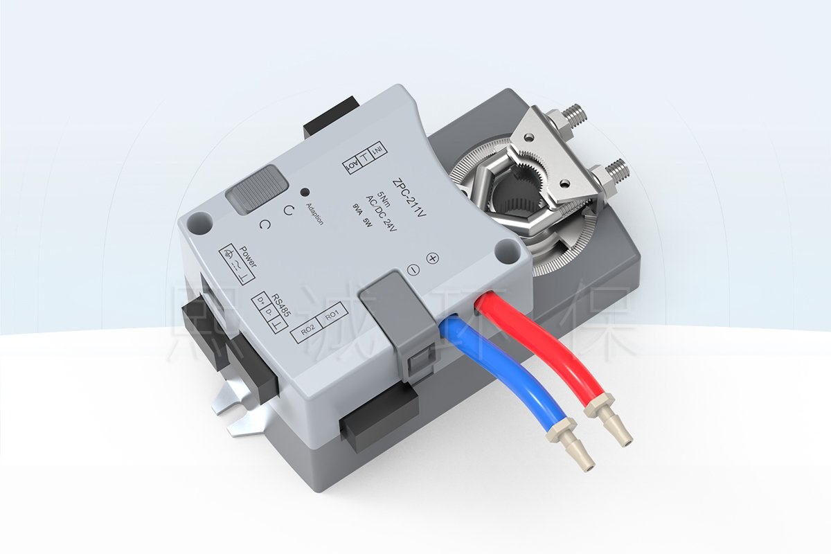
The ZPC211 zone pressure and airflow controller is an integrated-controller-and-actuator assembly for a defined laboratory VAV airflow-control task. It is intended to receive the selected pressure and airflow signals, command the connected rotary airflow-control device, and present the resulting interfaces to the project wiring and communication design. The unit is not a stand-alone room-pressure system: the final pressure relationship depends on the selected sensor arrangement, supply/exhaust airflow devices, sequence of operation, balancing, and commissioning.
ZPC211 at a Glance
Control Role
Use this zone pressure controller where a laboratory VAV assembly must coordinate a project-defined pressure or airflow objective through a rotary airflow-control device. The published ZPC-211V record shows pressure-tubing connections, airflow command and feedback terminals, an integrated rotary actuator, relay outputs, a panel interface, and RS-485 communication.
Published Hardware Reference
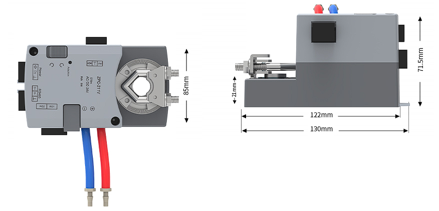
The first-source wiring record marks a 5 N m actuator, AC/DC 24 V supply, 9 VA / 5 W marking, adaptation function, manual clutch button, actuator direction switch, two relay outputs, and Modbus RTU on RS-485. The available body reference is 130 mm maximum length, 122 mm body length, 85 mm vertical envelope, and 71.5 mm maximum height.
Confirm Before Selection
Confirm the controlled zone, pressure reference, airflow device and shaft, airflow measurement method, actuator rotation, supply voltage, control and feedback signals, relay loads, local panel, RS-485 point requirements, alarm/failure sequence, and commissioning responsibility. These project fields determine the delivered configuration.
Product Overview
Where the Zone Pressure and Airflow Controller Fits
A zone pressure controller belongs between the selected measurement points and the airflow-control device. In a laboratory VAV application, the control strategy may use pressure relationships, airflow feedback, or both to determine how a connected damper or air valve should move. The ZPC211 record shows the connection points needed for that kind of assembly: low-voltage signal terminals, pressure tubing, an actuator interface, relay contacts, a display-panel port, and RS-485. It should therefore be selected as a controller for a configured airflow-control assembly, rather than as an independent sensor or as a generic building-management controller.
How It Fits Into a Laboratory VAV Control Loop
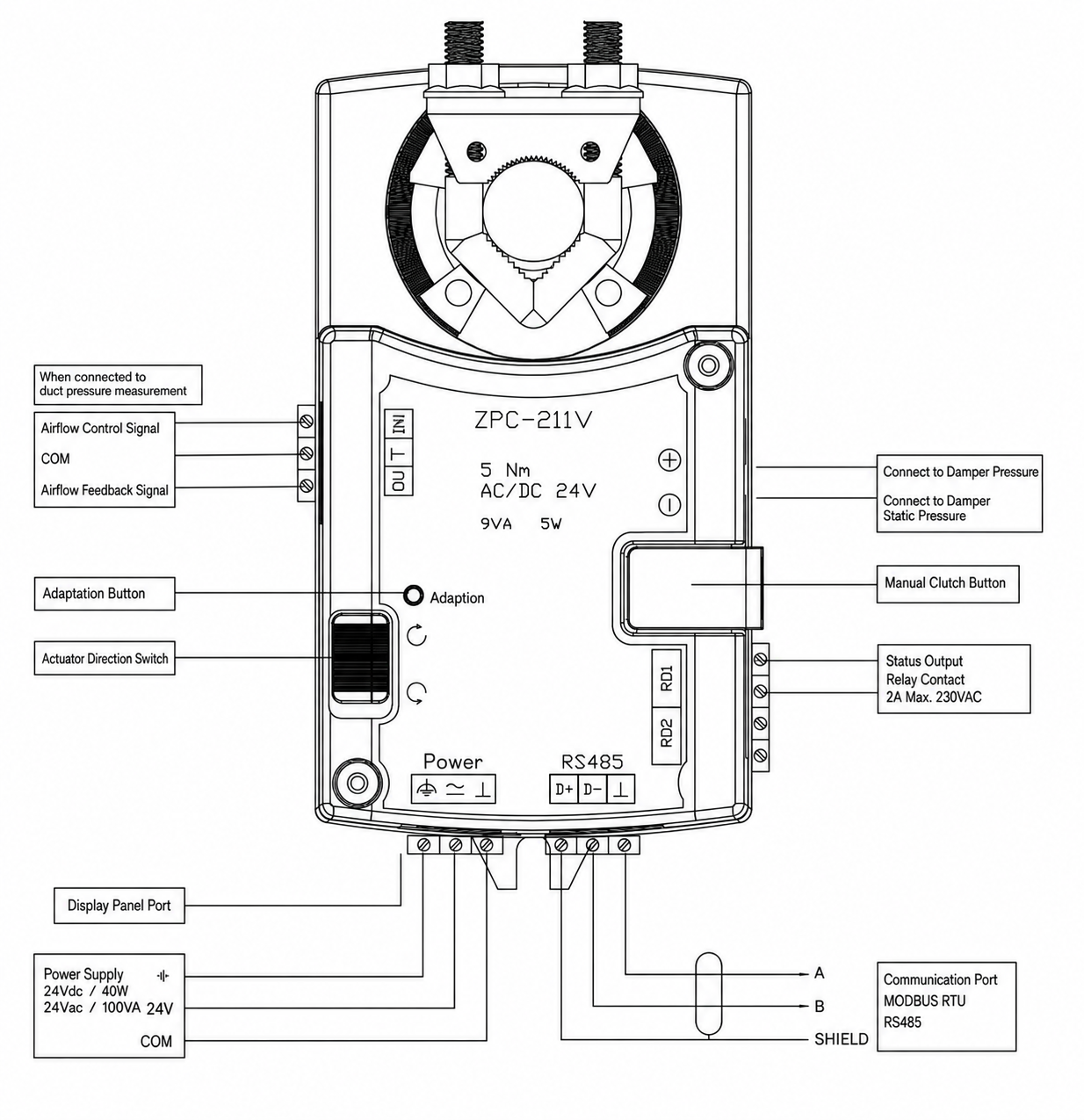
The available wiring illustration distinguishes a command signal, a common reference, and an airflow-feedback signal when the controller is connected to duct pressure measurement. It also identifies pressure connections for the duct and the damper static-pressure side. In a completed loop, those inputs are interpreted by the selected control sequence and the integrated actuator changes the position of the connected rotary device. The actual relationship between room pressure, airflow, actuator position, and alarm response is established by the project sequence and verified during commissioning; an actuator position alone does not prove the required airflow or pressure relationship.
Product and System Boundary
The controller does not replace the airflow-control device, pressure sensor package, local display, BMS programming, ductwork, balancing, or the final acceptance procedure. A project can use the ZPC211 with a defined supply or exhaust airflow-control arrangement, but the selected valve or damper, shaft geometry, sensor location, signal scaling, panel requirement, network points, and failure response must be specified together. This boundary keeps the product page useful for engineering selection without presenting a single hardware item as a complete laboratory ventilation system.
Product Selection Summary
Choose This Controller When
Choose the ZPC211 zone pressure and airflow controller when the project needs a compact controller with an integrated rotary actuator for a laboratory airflow-control device, and the design team has identified the measurement inputs and operating sequence that define the airflow or pressure target. It is suited to configured supply or exhaust arrangements in which the controller must exchange signals with an airflow sensor, local interface, relay-controlled equipment, or an RS-485 network. It is particularly relevant where the physical actuator, the signal interfaces, and the pressure-tubing connection are all part of the supplied control assembly.
Conditions To Confirm Before Selection
- The controlled zone and whether the sequence is led by an airflow target, a pressure relationship, or a coordinated combination of both.
- The selected damper or valve, shaft size and direction, mounting clearance, mechanical load, and the required failure position.
- The pressure-pickup arrangement, airflow-feedback method, sensor scaling, and the reference used for any differential-pressure measurement.
- The AC/DC 24 V power arrangement, command and feedback signal types, relay loads, local display requirement, RS-485 point list, and shielding/grounding approach.
- The minimum, normal, maximum, setback, alarm, and emergency operating sequence together with the method used to verify the installed result.
Information Needed To Configure the Product
Provide the application, drawings of the airflow-control assembly, duct size, actuator-shaft details, required rotation, pressure reference, airflow range or target, intended sensor inputs, 24 V power source, command and feedback signals, relay functions, local-panel requirement, communication protocol and point list, alarm/failure sequence, quantity, destination, and commissioning responsibility. The documented configuration should identify the selected controller revision, actuator interface, supplied sensors and panel, I/O schedule, wiring and tubing requirements, supplied scope, outstanding confirmations, and commercial pricing.
Key Specifications
ZPC211 Controller and Interface Data
The following entries are taken from the published ZPC-211V product record and its wiring illustration. They identify the controller interfaces that must be reviewed during selection. They are not a substitute for the final project wiring schedule or control sequence.
| Item | Published Reference | Selection Note |
|---|---|---|
| Configuration reference | ZPC211 / ZPC-211V | Confirm the delivered revision for the project. |
| Integrated actuator marking | 5 N m rotary actuator | Verify shaft, rotation, load, mounting, and failure requirement with the airflow-control device. |
| Power marking | AC/DC 24 V; 9 VA / 5 W | Coordinate the actual supply, protective device, and controller/actuator load. |
| Airflow signal interface | Command, common, and airflow-feedback terminals shown | Confirm signal type and scaling for the selected configuration. |
| Pressure connection | Duct and damper static-pressure connections shown | Confirm tubing routing, pickup locations, and reference pressure. |
| Outputs and network | Two relay outputs; RS-485 marked Modbus RTU | Confirm relay duty, point list, address, wiring topology, and BMS responsibility. |
| Local interfaces | Display-panel port, adaptation control, manual clutch, direction switch | Confirm the supplied panel and allowed setup procedure. |
Dimensions and Mounting Envelope
The illustrated body reference shows a 130 mm maximum length, 122 mm body length, 85 mm vertical envelope, 71.5 mm maximum height, and a 21 mm actuator-side projection. Use these values to review local clearance around the shaft, pressure tubing, terminals, panel connection, and manual controls. The final installation drawing must still account for the selected airflow-control device, linkage or shaft, enclosure, cable bend radius, and service access.
Pressure, Airflow, and Control Functions
Differential-Pressure Inputs and Airflow Feedback
The ZPC211 wiring record identifies two pneumatic connections: one associated with duct pressure and one associated with damper static pressure. It also shows airflow command and airflow-feedback terminals. In a configured VAV assembly, these connections and signals provide the information used by the selected sequence to compare the required condition with the measured condition. The tubing arrangement, pickup location, sensor range, calculation method, and alarm limits are project values; they must be defined for the particular duct and airflow-control device rather than inferred from the controller name.
Damper-Actuator Command and Feedback
The published unit combines the controller with a 5 N m rotary actuator marking. The diagram identifies command, common, and feedback connections, while the mechanical interface must be checked against the selected damper or valve shaft and its required direction of rotation. An integrated actuator reduces the number of separate mounting interfaces, but it does not remove the need to confirm torque, travel, linkage geometry, load, manual-operation access, and the required position when the control signal or power is unavailable.
Local Inputs, Relay Outputs, and Communication
The wiring reference shows local inputs for a face-velocity sensor, occupancy sensor, sash-position sensor, and exhaust-air-temperature sensor, as well as two relay outputs, a display-panel port, and RS-485 labelled Modbus RTU. These labels identify available interface fields, not an automatic promise that every input, function, panel, or network point is included in every configuration. The final I/O schedule should state which terminals are assigned, which devices provide the signals, what each relay controls, and how the controller communicates with the project BMS or local display.
Adaptation and Manual Operation
The controller illustration identifies an adaptation control, a manual clutch button, and an actuator-direction switch. These features are relevant during installation and functional testing, but they must be used according to the approved setup procedure for the selected airflow-control assembly. After any adaptation or manual movement, verify the actual airflow or pressure response through the project measurement method; a correct-looking actuator position is not sufficient evidence that the laboratory pressure relationship has been achieved.
Integration With the Airflow-Control Device
Rotary Damper Interface
The ZPC-211V reference identifies an integrated rotary actuator. Before selecting the controller, compare the selected damper or air valve shaft, shaft engagement, rotation direction, operating angle, mechanical stop, required torque, linkage arrangement, and available mounting space with the actuator interface. A controller may be electrically compatible with a project control sequence while still being mechanically unsuitable for a particular airflow-control device. The selected valve or damper remains a separate product whose size, material, leakage requirements, chemical exposure, and connection type must be evaluated independently.
Duct and Damper Static-Pressure Connections
The published wiring illustration labels one pressure connection for the duct and another for damper static pressure. Keep those functions distinct when designing the tubing path. Verify the pressure pickup locations, tube length and routing, connection security, condensate risk, protection from damage, and the measurement reference used by the sequence. A pressure connection is part of the installed control loop; it does not by itself establish a room pressure relationship or validate airflow without the final sensor arrangement and commissioning test.
What Is Confirmed Per Project
Confirm whether the controller is applied on supply, exhaust, or another selected airflow-control branch; which device it drives; which signals determine the target; which feedback closes the loop; whether a display panel is supplied; and how alarms, relay outputs, and RS-485 points are assigned. The controller, actuator, pressure tubing, sensor package, valve or damper, panel, and BMS interface should be documented as one project configuration, with their supplied and excluded scope stated clearly.
Applications and Project Fit
Laboratory Supply and Exhaust Coordination
Use a zone pressure and airflow controller where a laboratory ventilation design requires a defined supply or exhaust branch to respond to a project control sequence. Typical decision inputs can include a required airflow condition, a pressure reference, a local demand input, or a signal from a coordinated laboratory control package. The selected assembly can support a controlled pressure relationship only when its airflow devices, sensors, sequence, and commissioning method are designed as a coordinated system.
Pressure-Relationship Control Context
Laboratory pressure control is a system outcome, not a controller label. The required relationship is established by the relative operation of supply and exhaust air, the reference space, room leakage, door movement, equipment demand, duct conditions, and the project control sequence. The ZPC211 provides controller, actuator, pressure-connection, I/O, relay, panel, and communication interfaces that can be incorporated into such an arrangement. It does not remove the need for the project engineer to define the target condition, sensor locations, control priority, alarm logic, and verification procedure.
When a Different Product Should Be Evaluated
Evaluate a differential-pressure sensor when the requirement is measurement and signal transmission without an integrated actuator. Evaluate a laboratory room controller when one controller must coordinate multiple room supply/exhaust devices, balance logic, and room-level sequences. Evaluate a fume hood controller when the principal control object is a fume hood with sash or face-velocity demand. Evaluate a separate actuator controller when the project requires a controller to drive an external actuator rather than an integrated rotary actuator. These related products serve different control boundaries even when they share signals or communication requirements.
Installation, Wiring, and Commissioning
Mechanical and Electrical Checks Before Installation
Before installation, verify the controller revision, actuator-to-shaft engagement, rotation direction, mechanical clearance, accessible manual controls, pressure-tube routing, 24 V supply arrangement, protective device, signal common, relay loads, display-panel connection, network cable route, grounding, and separation between low-voltage signal wiring and higher-voltage relay circuits. The dimension reference is useful for clearance review, but it does not replace the complete assembly drawing or the actual site enclosure requirements.
Wiring Terminal Reference
The available illustration identifies power, airflow command and feedback, sensor-related inputs, relay contacts, a display-panel port, and RS-485. Use it as an interface reference while preparing the final terminal schedule. The wiring design should identify the exact signal type, polarity, common reference, shield termination, relay voltage/current duty, BMS point mapping, and responsibility for each connected device. Do not terminate a selected actuator or sensor only from a generic family diagram when the approved configuration requires a different signal range or pin assignment.
Pressure Tubing and Signal Coordination
Route the duct and damper-static pressure tubes to their defined measurement points, protect them from kinks and damage, and verify that the tubing connections match the control sequence. Confirm the airflow feedback scaling and the relationship between sensor reading, controller signal, and actuator motion. Any change to the pressure pickup, tubing, airflow-control device, or control sequence can require the system to be rechecked before acceptance.
Functional Testing and Acceptance
After installation, verify safe mechanical travel, correct actuator direction, pressure-tube connections, command and feedback signals, relay response, panel operation when supplied, communication points, alarms, and the defined failure response. Then test the installed airflow or pressure result using the project measurement method across the required operating states. Record the final settings, measured results, open items, point assignments, and the approved controller, sensor, airflow-device, and wiring revisions for handover.
How To Select and Specify the Controller
Define the Zone Control Objective
State whether the selected branch is supply or exhaust, what airflow or pressure relationship it supports, what condition has priority, and which operating states must be handled. Include normal operation, reduced-flow or setback operation where applicable, alarms, emergency response, and the defined behavior for sensor, network, or power loss. A zone pressure controller can only be configured correctly when the project sequence defines what it is meant to control.
Match Sensors, Actuator, and Airflow Device
Identify the pressure pickup, airflow-feedback method, sensor signal range, selected valve or damper, shaft and rotation, actuator load, and final mechanical arrangement. The controller wiring record shows relevant connection fields, but each field must be mapped to the physical device and signal used in the installation. Confirm whether the local display and each relay function are supplied, optional, or provided by others.
Confirm I/O, Network, Alarm, and Failure Sequence
Provide the final I/O list, relay duty, display requirement, RS-485 point list, network addressing responsibility, alarm sequence, and fail-state requirements. The project documentation should identify the controller revision, selected airflow-control device, sensor package, wiring and tubing drawing, control sequence, supplied scope, installation responsibility, commissioning method, and required handover records.
Technical Data, Configuration, and Documentation
Data Needed for the Final Configuration
Submit the application, controlled zone, airflow-device drawing, shaft details, airflow target or range, pressure reference, sensor details, power supply, signal and feedback requirements, relay loads, panel requirement, BMS point list, alarm/failure sequence, quantity, destination, and site responsibilities. This information supports a configuration that can be installed, wired, commissioned, and maintained as a defined assembly.
Documents for Installation and Handover
Depending on the selected configuration, the supplied documentation can include controller and mounting dimensions, terminal and wiring information, pressure-tubing reference, I/O schedule, point list, control-sequence details, and configuration-specific product data. These documents identify the actual delivered arrangement; the family-page reference alone is not an installation instruction for every possible system.
Related Products
Related Laboratory Control Products
For a duct branch whose primary task is airflow control, evaluate the Duct Airflow Controller. Where an external actuator is required, evaluate the Duct Airflow and Pressure Controller. For a VAV controller with a different integrated airflow-and-pressure control scope, evaluate the VAV Airflow and Pressure Controller. A future differential-pressure sensor or laboratory room controller should be selected separately when measurement-only or multi-device room coordination is the defined procurement task.
Related Airflow-Control Devices
The ZPC211 must be matched with a selected airflow-control device. Confirm whether the project uses a rotary damper, a butterfly valve, a Venturi air valve, or another approved device, then review the shaft interface, pressure pickup, control signal, feedback arrangement, mechanical load, material suitability, and commissioning sequence as one system.
Frequently Asked Questions
Is ZPC211 a differential-pressure sensor?
No. The ZPC211 record identifies a controller with an integrated rotary actuator, pressure-tubing connections, signal terminals, relay outputs, and RS-485. A differential-pressure sensor is a separate measurement product and should be selected by its measurement range, output, installation, and calibration requirements.
Does the controller itself create a room pressure relationship?
No. A laboratory pressure relationship is achieved by the installed supply/exhaust airflow devices, sensors, room leakage conditions, control sequence, and commissioning. The controller is one configured component within that assembly.
What does the integrated actuator connect to?
The published ZPC-211V record shows a 5 N m rotary actuator. The selected damper or valve shaft, rotation, load, mounting geometry, and required failure position must be confirmed for the individual project.
Which interfaces are shown on the wiring diagram?
The illustration shows airflow command and feedback, pressure connections, sensor-related inputs, relay outputs, a display-panel port, AC/DC 24 V power, and RS-485 labelled Modbus RTU. The final terminal schedule identifies which interfaces are used in the supplied configuration.
What must be confirmed before the controller is ordered?
Confirm the application, controlled zone, airflow device, pressure and airflow measurement method, sensor package, actuator interface, power, signals, relay duty, panel, BMS points, alarms, failure sequence, quantity, destination, and commissioning responsibility.
Contact the Xicheng Engineering Team Today.
Send the controlled-zone drawing, selected airflow device, pressure reference, airflow target, sensor and signal requirements, and control sequence. XICHENG can prepare a configuration and pricing aligned with the selected ZPC211 assembly.
Manufacturing Head Office: No. 34 Zhenxing Road (Shengtaian Heavy Industrial Park B), Loucun, Guangming New Dist, Shenzhen, Guangdong, China
Direct Hotline / WhatsApp: +86 18126478161
Engineering Mailbox: fanalax@gmail.com