


Description
Duct Airflow Control Damper for Measured VAV and Pressure Control
A duct airflow control damper regulates air volume from a measured signal rather than relying only on a commanded blade angle. This XICHENG product family combines a round PP butterfly damper, differential-pressure airflow pickup, controller and actuator for laboratory supply or exhaust branches. The same platform can be configured for variable airflow, a fixed or switched airflow setpoint, room differential-pressure control, or commanded damper position.
The damper changes the resistance of the branch while the fan and duct system provide the pressure that moves air. Its controller compares the selected setpoint with measured airflow, room pressure or actuator position, then drives the blade to reduce the difference. The final result depends on the complete loop, including the selected body size, pickup signal, controller, actuator, available pressure, upstream and downstream duct conditions, fan response and field commissioning.
What the Product Controls
In airflow mode, the controller receives an airflow setpoint through an analog signal, local panel or Modbus RTU. The differential-pressure measurement is converted to an airflow value for the selected damper body, and the blade moves until measured flow reaches the active setpoint. This closed-loop arrangement can compensate for normal duct-pressure changes within the commissioned operating range.
In room differential-pressure mode, the damper becomes the final control element for a supply or exhaust branch. A room-pressure sensor reports the pressure difference between the controlled space and its reference area. The controller then changes airflow to hold the selected pressure relationship. This mode also depends on the room envelope, door state, transfer path, paired supply or exhaust system and available fan authority.
Damper-position mode commands an angle rather than a measured airflow. It is useful for setup, override or sequences that intentionally control position, but the resulting airflow varies with duct pressure and system resistance. Position feedback should therefore be treated as mechanical confirmation, not as an airflow measurement.
Choose This Product Family When
- A laboratory supply or exhaust branch requires measured variable or constant airflow rather than a manually balanced blade position.
- The air stream calls for a round PP damper body and the complete exposed assembly can be reviewed for the process conditions.
- The project requires analog control, local adjustment or Modbus RTU communication with actual-value feedback.
- Room differential-pressure control is required and the design includes an external room-pressure sensor, a defined reference space and coordinated supply/exhaust airflow.
- The buyer can provide minimum, normal, maximum and emergency airflow together with the available pressure at the installed location.
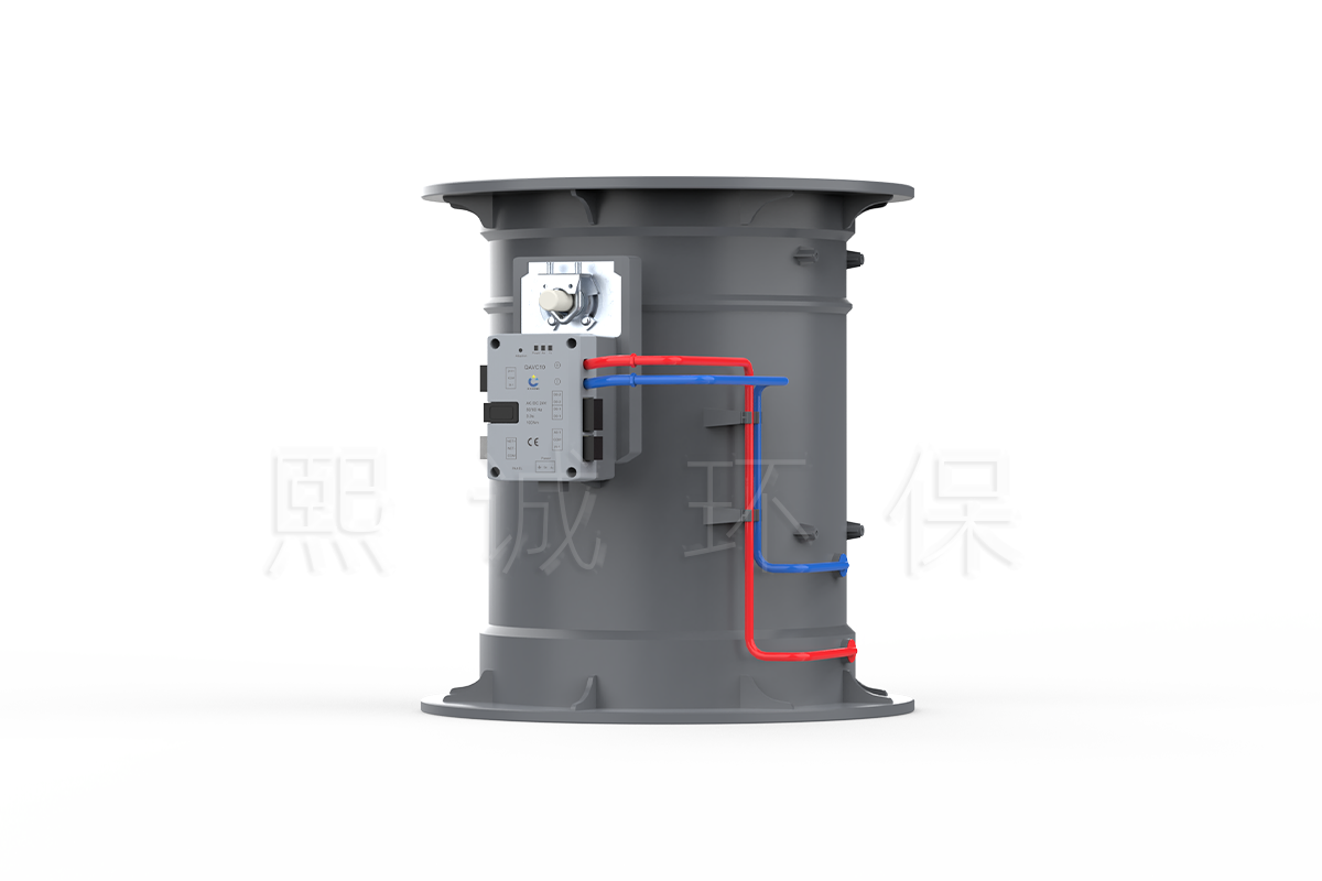
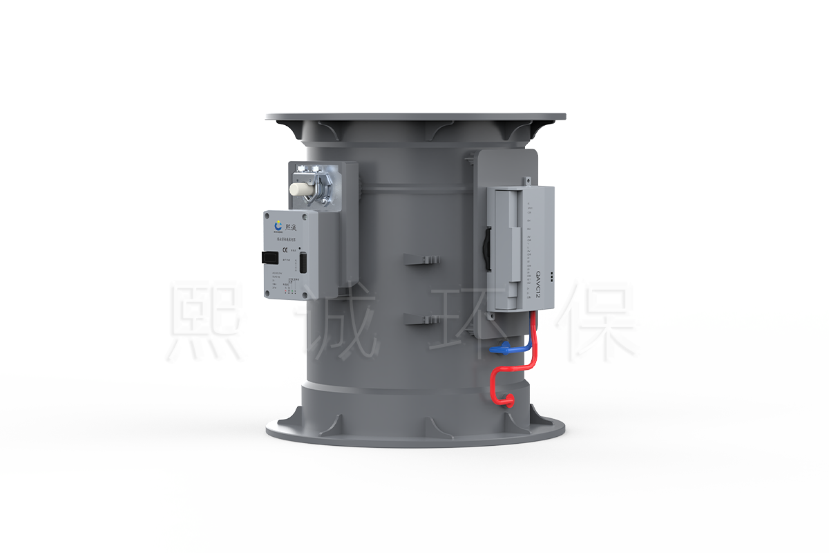
Choose the integrated QAVC10 architecture when compact installation and a controller with a fast actuator are preferred. Choose the QAVC12 architecture when the controller must be separate or the actuator needs to be selected independently for torque, motion, signal, feedback, shaft arrangement or service strategy.
Do Not Select It from the Product Name Alone
This page covers a measured duct-control package, not every round motorized damper. If the project only needs a general round modulating body and will provide its own measurement and controller, use the Round VAV Butterfly Damper. If the connection is rectangular, use the Rectangular VAV Butterfly Damper.
For a fume hood, measured duct airflow can support the exhaust-control strategy, but it does not by itself measure sash position or hood face velocity. A hood that requires local alarms, sash tracking or direct face-velocity control should use the Fume Hood VAV Control Damper or another specifically scheduled hood-control package.
The product is not a Venturi air valve, fire damper, smoke damper, passive backdraft damper or certified isolation device. Its control element is a rotating butterfly blade. Where a specification requires a Venturi mechanism, evaluate the planned VAV Venturi Air Valve.
Key Specifications, Sizes and Airflow References
Start selection with the operating airflow and pressure condition, then check the body size and controller architecture. The published values below describe available configurations in this product family. The final valve tag must identify which body, connection, controller, actuator, inputs, outputs and operating points apply to the delivered assembly.
Product-Family Specifications
| Selection Item | Available Product Information | Application Boundary |
|---|---|---|
| Product type | Round PP butterfly damper with measured airflow and pressure-control options | For laboratory duct branches; not a fire, smoke or isolation damper |
| Body material | Flame-retardant PP; V-2 standard and V-0 customization identified for the body family | Review all exposed components against the actual air stream |
| Internal-diameter references | 110, 125, 160, 200, 250 and 315 mm | Final diameter follows the complete airflow and pressure schedule |
| Connection forms | Flange; socket references for 110, 125, 160 and 200 mm | Confirm mating duct, insertion depth and service clearance |
| Controller architecture | QAVC10 integrated controller/actuator or QAVC12 separate controller with external actuator | Do not combine their I/O and actuator data into one assumed configuration |
| Control modes | Variable airflow, constant airflow, multiple airflow states, room differential pressure or damper position | Each tag uses the modes and sensors defined by its approved sequence |
| Published control-package accuracy | No more than +/-4% | Applies to the corresponding measured and commissioned package |
| Published adjustment ratio | 16:1; up to 25:1 for selected configuration | Confirm minimum and maximum flow for the selected body and sensor range |
| Published operating pressure range | 150-750 Pa | Applies to the configured measurement and control arrangement |
| Published control response | Less than 1 second | Controller response is different from actuator travel and loop stabilization |
| Communication | RS-485 Modbus RTU and RJ12 local-panel interface | Confirm points, baud rate, addressing and communication-loss behavior |
These performance values do not apply to the bare body in isolation. Airflow accuracy and usable range depend on the pressure pickup, tubing, controller conversion, body calibration, actuator authority and installation. Room-pressure performance additionally depends on the external pressure sensor, room envelope and coordinated supply/exhaust system.
Round PP Damper Size and Velocity-Reference Table
The airflow columns convert three reference duct velocities into volume for each listed internal diameter. Use them to compare body sizes, not as preset controller limits. A project may require a smaller operating range than the table or a different body after minimum-flow signal, maximum velocity, noise, pressure loss and connection constraints are evaluated.
| Model | Flange OD D1 | Internal D | Body Length L | Socket Depth L1 | At 1 m/s | At 6 m/s | At 10 m/s |
|---|---|---|---|---|---|---|---|
| VAV-R/110 | 185 mm | 110 mm | 240 +/- 3 mm | 25 mm | 34 CMH | 205 CMH | 342 CMH |
| VAV-R/125 | 200 mm | 125 mm | 240 +/- 3 mm | 25 mm | 44 CMH | 265 CMH | 441 CMH |
| VAV-R/160 | 240 mm | 160 mm | 280 +/- 3 mm | 30 mm | 72 CMH | 434 CMH | 723 CMH |
| VAV-R/200 | 280 mm | 200 mm | 300 +/- 3 mm | 30 mm | 113 CMH | 678 CMH | 1,130 CMH |
| VAV-R/250 | 339 mm | 250 mm | 363 +/- 3 mm | 40 mm | 100 CMH | 968 CMH | 1,600 CMH |
| VAV-R/315 | 395 mm | 315 mm | 423 +/- 3 mm | 53 mm | 150 CMH | 1,579 CMH | 2,400 CMH |
The published DN250 row lists 100 CMH at 1 m/s, while its 6 m/s and 10 m/s entries are 968 and 1,600 CMH. The low-velocity value is retained as published because it is not appropriate to substitute an unapproved calculation into the product table. Confirm the applicable selection data and minimum measurable flow before the DN250 configuration is ordered.
Flange and Socket Mechanical Envelope
The connection style changes the outside envelope and the way the body enters the duct. The drawing distinguishes the socket body by internal diameter D, body length L and insertion depth L1, while the flange body adds outside flange diameter D1. Review these dimensions together with the side-mounted controller, actuator and pressure-tube clearance.
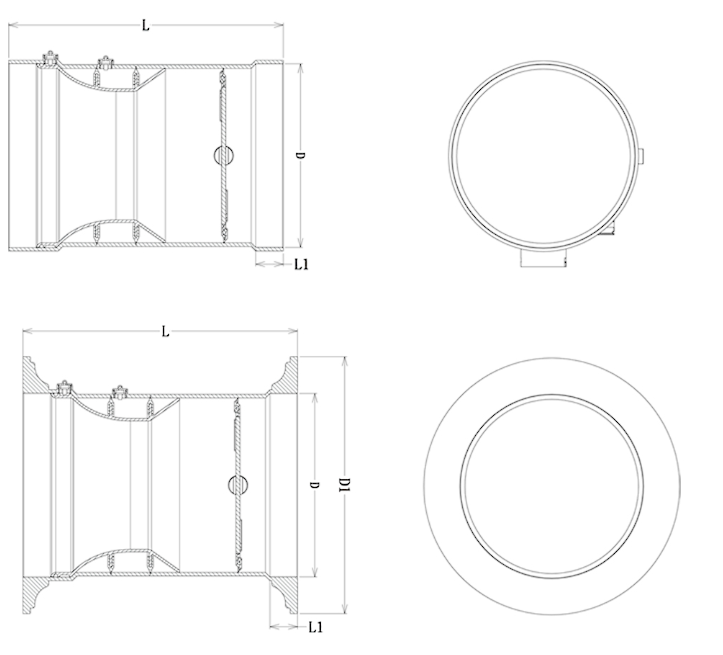
The drawing establishes the dimension convention rather than one universal size. Use the table row and approved product drawing for the selected diameter. Leave enough space to remove the controller or actuator, inspect the pressure pickups, route tubing without kinks and reach the wiring terminals. Duct supports should not transfer misalignment or external load into the PP body.
Integrated and Separate Control Architectures
QAVC10 and QAVC12 perform related airflow and pressure-control tasks, but they place the controller and actuator in different physical arrangements. Select the architecture before finalizing wiring, mounting clearance and the I/O schedule. A model number alone does not define the delivered package; the valve tag should list the body, controller, actuator, sensor inputs and communication requirements.
| Selection Point | QAVC10 Integrated Configuration | QAVC12 Separate Configuration | Project Decision |
|---|---|---|---|
| Architecture | Controller, differential-pressure sensor and fast rotary actuator integrated at the damper | Separate controller commands a selected rotary or linear external actuator | Choose compact integration or independent actuator selection |
| Controller power | 24 VAC/DC +/-10% | 24 VDC controller; confirm actuator power separately | Coordinate transformer capacity and field wiring |
| Primary analog input | Airflow setpoint, room-pressure input or angle input | Room-pressure/setpoint input plus temperature, humidity and actuator-feedback inputs | Match the controller to the required sensor and point list |
| Analog output | Airflow, pressure or actuator-position feedback | Separate outputs for actuator command and airflow feedback | Define command and feedback scaling |
| Digital I/O | Door-switch input; operating-status and lighting outputs | Door-switch input; operating/fan-status and lighting outputs | Confirm contact ratings and ownership of connected equipment |
| Local/BMS interfaces | RJ12 local-panel port and RS-485 Modbus RTU | RJ12 local-panel port and RS-485 Modbus RTU | Issue a final network and point schedule |
| Actuator selection | 5 Nm/2 s, 15 Nm/5 s or 30 Nm/9 s listed for 0-90 degree travel | External actuator selected by torque, motion, speed, signal, feedback, shaft and enclosure | Verify actual blade load and fail behavior |
| Best-fit use | Compact measured airflow damper with simplified field assembly | Projects needing actuator choice, remote controller location or easier component replacement | Select from installation and maintenance requirements |
QAVC10 Integrated Controller and Actuator
QAVC10 combines the controller, airflow differential-pressure sensor and rotary actuator in one damper-mounted assembly. Its published actuator choices cover 5 Nm at 2.0 seconds, 15 Nm at 5.0 seconds and 30 Nm at 9.0 seconds for a 0-90 degree stroke. The higher-torque versions are not automatically better: torque must exceed the actual blade and seal load, while the required control response determines the acceptable travel time.
The controller supports an analog voltage or current input for airflow demand, room differential-pressure signal or position demand. It can return airflow, pressure or actuator-position feedback and accepts a dry-contact door input for pressure-control sequences. Operating-status and lighting outputs, an RJ12 panel connection and Modbus RTU support local operation and BMS integration. The final point list must identify which values are active for the selected mode.
The integrated layout reduces separate mounting and actuator-matching work. It is appropriate where the standard actuator choices fit the body and service access is available at the damper. If the controller must be mounted away from the air stream or a different actuator specification is mandatory, the separate architecture is more suitable.
QAVC12 Separate Controller and External Actuator
QAVC12 separates the control electronics from the actuator and provides an analog command to the selected drive. Its confirmed inputs include room-pressure or airflow demand, room temperature, room humidity and actuator-position feedback. It also provides airflow feedback, door-switch input, operating/fan-status and lighting outputs, an RJ12 panel port and Modbus RTU communication.
This architecture allows a rotary or linear actuator to be chosen for the actual mechanism. One paired fast rotary actuator documented with the product uses 24 VAC/DC power, more than 5 Nm torque, a 2-10 VDC or 4-20 mA command, 2-10 VDC feedback and a 2-second 90-degree travel time. Its position accuracy is listed as better than +/-0.5%, with IP53 protection and an 8-15 mm round or 10 x 10 mm square shaft interface. Those values describe that actuator option, not every QAVC12 package.
A separate controller increases flexibility but adds coordination. The controller output range, actuator input, position feedback, power source, rotation direction, travel limits, shaft adapter and fail response must match. The wiring diagram should identify the actual selected actuator rather than a generic symbol.
Configuration Comparison
Use QAVC10 when the controller and fast rotary actuator can remain together and one of the listed torque/speed combinations meets the mechanical load. Use QAVC12 when an external actuator is already specified, a linear drive is needed, the controller should be remote, or the project requires independent replacement of the controller and actuator.
Both architectures still require the same airflow-control fundamentals: a known body size, correctly connected differential-pressure pickup, valid setpoint, sufficient fan pressure and field calibration. Neither architecture should be selected solely because it offers more I/O. Additional inputs for temperature or humidity matter only when the control sequence uses them and the associated sensors are included.
Airflow, Pressure and Position Control Modes
The selected control mode determines what the controller treats as the controlled variable. Variable airflow, constant airflow, room differential pressure and damper position may use the same mechanical body, but they require different setpoints, sensors and acceptance tests. One valve tag can include more than one operating state, yet its normal mode and override hierarchy must remain unambiguous.
Variable Airflow Control
In variable airflow control, the active setpoint changes according to an analog command, local panel setting or Modbus RTU value. The controller reads the differential-pressure signal associated with the damper body, converts it to airflow and compares the result with demand. It then opens or closes the butterfly blade until the measured airflow reaches the requested value within the commissioned range.
This mode suits branches where ventilation demand changes with process state, occupancy, temperature, exhaust requirement or another approved control input. The upstream fan must maintain enough pressure for the maximum scheduled flow, and the damper must retain useful control authority at minimum flow. If the blade remains fully open and airflow is still low, the problem is usually available pressure or system resistance rather than controller tuning.
Constant and Multiple-State Airflow Control
A constant-airflow configuration holds one commissioned setpoint despite normal changes in duct static pressure. A multiple-state configuration switches among two or more defined values, such as occupied, unoccupied and emergency flow. The selected state can come from a dry contact, analog command, panel or network sequence, depending on the I/O assigned to the controller.
Each state needs a numeric airflow value, transition rule and priority. An emergency command should not be left as a label with no scheduled flow. Likewise, an unoccupied setting must still satisfy the process, pressure and safety requirements of the room. Where only one passive factory-set airflow is needed and no powered controller or network is required, a Constant Air Volume Damper may be the simpler product.
Room Differential-Pressure Control
Room-pressure mode changes branch airflow to maintain a pressure difference between the controlled room and a defined reference space. For a pressure-independent airflow damper, the internal differential-pressure sensor continues to measure damper airflow, while an external room differential-pressure sensor supplies the room-pressure signal. The controller modulates the supply or exhaust branch according to the approved sequence.
The target cannot be achieved by the damper alone. The room envelope must have a predictable leakage or transfer path, the door state must be considered, and the paired supply or exhaust system must have enough capacity and response. A door contact can tell the controller that the room is temporarily open, but it does not measure pressure. The sequence should define the response during door opening, sensor failure, fan shutdown and communication loss.
Where a dedicated room controller must coordinate several supply and exhaust devices, alarms and trend data, use the appropriate Zone Pressure Controller and treat this damper as one final control element. The controller hierarchy should prevent two independent loops from fighting over the same branch.
Damper-Position Control
Position mode drives the actuator toward a commanded angle and can return position feedback. It is useful for manual override, setup, purging or a sequence in which another controller owns the airflow loop. The same angle will not always produce the same airflow because fan pressure, filters, downstream resistance and other damper positions change.
Use position feedback to confirm mechanical movement and direction. Use measured airflow to confirm air volume, and use a room-pressure sensor to confirm pressure. These three signals answer different questions and should not be substituted for one another during acceptance.
Sensors, Interfaces and Supply Boundary
A complete duct airflow control damper can include the PP body, blade, pressure pickups, tubing, controller, actuator and selected local interface. The quotation should identify which components are factory mounted, which are shipped loose and which are supplied by the controls contractor. This prevents missing sensors or duplicated control responsibility during installation.
Airflow Measurement and Pressure Tubing
The round body uses differential-pressure pickup geometry to produce a measurement signal related to airflow. High and low pressure connections must reach the correct controller ports. Tubing should be short, supported and free from reversed connections, kinks, leaks, condensate traps or process deposits. A blocked or wet tube can produce a false airflow reading even when the actuator and blade operate normally.
The controller must use the correct body relationship for the selected diameter. Replacing a body or controller without restoring the proper size and calibration data can shift the indicated flow. The measurement section also needs the installation conditions specified for the supplied configuration; nearby elbows, transitions or obstructions should be reviewed rather than assumed harmless.
Analog I/O, Local Panel and Modbus RTU
Analog inputs can carry airflow demand, room-pressure signal, temperature, humidity or position feedback according to the controller architecture. Analog outputs can carry actuator command or an actual-value signal. Before wiring, document whether each signal uses voltage or current, its engineering range, common reference and failure behavior. A 0-10 V connection should not be assumed interchangeable with a 4-20 mA loop.
Both controller architectures provide a local-panel interface and Modbus RTU support. The BMS point list should identify setpoint, measured airflow, room pressure where applicable, blade position, mode, status, alarms and override commands that are actually available. Define baud rate, parity, address, scaling, writable limits and the local fallback after network loss. The local control loop should continue safely according to the approved sequence rather than depending on continuous supervisory commands.
What the Package Does Not Replace
The product does not replace the supply or exhaust fan, variable-frequency drive, room differential-pressure sensor, transfer-air path, duct sizing, test-and-balance work or building controls sequence. It cannot overcome a fan that lacks pressure, a room with uncontrolled leakage or a branch that is outside the damper’s measurable range.
It is also not a fume hood containment monitor. When installed on a hood exhaust branch, the damper can regulate duct airflow, but hood face velocity, sash state and containment still require the appropriate hood sensors and acceptance procedure. The same distinction applies to cleanroom or isolation-room projects: airflow control supports room pressure, but the pressure relationship must be measured and verified at the room.
Applications, Configuration and RFQ Information
This duct VAV damper is intended for controlled laboratory branches where airflow must be measured and adjusted automatically. A reliable selection begins with the duty of the branch and its complete operating range, not with the nearest nominal duct diameter.
Good-Fit Applications
Typical applications include laboratory general exhaust, process-equipment exhaust, room supply air, room exhaust, make-up air and supply/exhaust tracking branches. The PP body is relevant when a nonmetallic flow-control component is preferred for the air stream. QAVC10 suits compact integrated installations, while QAVC12 suits projects that require a separate controller or independently selected actuator.
Room differential-pressure control can use the damper to trim supply or exhaust flow in laboratories, clean support areas, selected healthcare rooms or other controlled spaces. The application is appropriate only when the pressure sensor location, reference area, transfer path, door behavior and fan sequence are defined. If several dampers must coordinate as one room system, the project should identify the supervisory room controller and the role of each damper.
For chemical exhaust, provide the chemicals, concentrations, temperatures, condensate risk and cleaning agents. PP body construction does not automatically approve the shaft, seals, blade covering, pressure tubing, fittings or external hardware. The configuration review should cover every exposed component and the consequences of condensation or deposits in the measurement path.
Conditions Requiring Another Product
Choose the Round VAV Butterfly Damper when the project already has a separate airflow station and controller or only needs a modulating PP body. Choose the Rectangular VAV Butterfly Damper for rectangular duct connections or larger custom cross-sections.
Use the Fume Hood VAV Control Damper when sash position, direct face velocity, local hood alarms or operator functions are part of the product scope. Evaluate a VAV Venturi Air Valve when the specification requires a Venturi mechanism rather than a butterfly blade. Use a rated fire or smoke damper wherever life-safety certification is required.
Selection Sequence
- Define whether the branch controls variable airflow, constant airflow, multiple states, room differential pressure or damper position.
- List minimum, normal, maximum and emergency airflow for every damper tag.
- State the available static pressure at the damper across the expected system operating conditions.
- Select the internal diameter after checking minimum measurement signal, maximum velocity, noise, pressure loss and connection fit.
- Confirm PP and all exposed component materials against the actual air stream.
- Choose QAVC10 integrated control or QAVC12 with an external rotary or linear actuator.
- Define every sensor, analog signal, dry contact, local-panel function and Modbus point.
- Set fail position, communication-loss behavior, fan interlock, emergency state and restart sequence.
- Issue the installation, calibration and acceptance requirements with the product schedule.
Do not size from maximum flow alone. An oversized body can weaken the differential-pressure signal at minimum flow and reduce control authority. An undersized body can create excessive velocity, pressure loss and noise. The selected body must serve the entire operating envelope, including emergency or setback states.
Information Required for Configuration and Quotation
For each damper tag, provide the application, control mode, minimum/normal/maximum/emergency airflow, duct diameter, connection type, available pressure, installation orientation and service clearance. Add the air-stream chemistry, temperature, humidity, condensation and cleaning conditions needed for material review.
For QAVC10, identify the required torque/travel option and whether the analog input represents airflow demand, room pressure or position. For QAVC12, identify the external actuator type, torque or force, rotary or linear motion, travel time, shaft or linkage, command, feedback, power and enclosure requirement. For room-pressure control, include the sensor range, reference location, door-contact logic, supply/exhaust relationship and pressure setpoint.
Provide the duct layout, controls schematic, I/O list and BMS point list when available. The returned product schedule can then identify the selected damper body, controller architecture, actuator, sensors, connection, applicable performance values, drawing references, supplied accessories and pricing.
Installation, Commissioning and Acceptance
Mechanical installation, measurement setup and control commissioning must be completed as one task. A damper can be correctly wired and still report the wrong airflow if its pressure tubes are reversed, the wrong body data are loaded or the branch lacks sufficient fan pressure.
Before Installation
Compare the approved drawing with the duct diameter, flange or socket connection, body length, airflow direction and available access. Support the adjacent duct independently and align the connections before tightening them. The PP body should not be pulled into position by flange bolts or used to carry unsupported ductwork.
Reserve clearance for the controller, actuator, manual release, wiring terminals and pressure tubing. Keep the electronics accessible without removing unrelated duct sections. Follow the product-specific straight-duct and orientation requirements, especially where an elbow, transition, fan discharge or branch takeoff is close to the measurement section.
Connect high and low pressure tubes to their marked ports. Keep tubing short, secure and free of sharp bends, leaks, trapped liquid or contact with hot surfaces. Verify power voltage, grounding, signal type and common reference before energizing the controller. For QAVC12, check the external actuator’s command, feedback, rotation direction, shaft connection and travel limits against the wiring and mechanical drawings.
Airflow-Mode Commissioning
- Inspect the body, blade, shaft, actuator and tubing, then confirm that the branch is clean and unobstructed.
- Operate the actuator through its permitted travel and verify open/close direction without forcing mechanical stops.
- Confirm the controller uses the selected body size and applicable airflow relationship.
- Zero the differential-pressure sensor under the required no-flow or equal-pressure condition.
- Enter minimum, normal, maximum, setback and emergency airflow values from the approved schedule.
- Apply each setpoint and compare displayed or network airflow with the accepted field measurement method.
- Verify that the damper has control authority and does not remain at a travel limit during normal operation.
- Test analog command and feedback, local-panel functions, dry contacts, Modbus points and communication-loss behavior.
Record the field measurement, controller indication, blade position and upstream/downstream pressure at each operating point. If the maximum flow cannot be reached with the blade open, check fan pressure and duct resistance. If minimum flow is unstable, check measurement signal, tubing, body sizing and controller settings before changing the setpoint.
Room-Pressure-Mode Commissioning
Install and zero the room differential-pressure sensor with the correct high and low reference connections. Verify that the reference point represents the adjacent area named in the sequence and is not exposed to an unsuitable local draft. Confirm the intended pressure sign before enabling automatic control.
- Establish normal supply and exhaust operation and verify the airflow measurement on the controlled branch.
- Apply the room-pressure setpoint and confirm that the damper moves in the direction that corrects the pressure error.
- Test the normal door-closed condition, then observe recovery after the door is opened and closed according to the project method.
- Verify door-contact logic, occupied/unoccupied values, emergency mode and fan interlocks where specified.
- Confirm that supply and exhaust loops remain stable and do not hunt against one another.
- Test room-pressure sensor failure, communication loss and power restoration under the approved sequence.
Acceptance should record both room differential pressure and controlled-branch airflow. A correct room-pressure reading with an unexplained airflow value can hide an envelope or transfer-air issue, while correct airflow alone does not prove the required room relationship.
Maintenance and Revalidation
Inspect the blade, shaft, seals, pressure pickups, tubing, controller, actuator and wiring at the interval established for the laboratory. Clean deposits with methods compatible with the supplied materials. Confirm that tubing remains connected, dry and open, and that the actuator can complete its required movement without binding.
Recheck airflow after a controller, actuator, body, sensor or pressure tube is replaced. Revalidate room-pressure performance after changes to doors, transfer grilles, supply/exhaust fans, filters, ductwork or room sealing. A trend in increasing blade position at the same airflow can indicate rising system resistance and should be investigated before the valve reaches its travel limit.
Related Laboratory Air Damper Products
Use the Round VAV Butterfly Damper when the project will supply its own controller and airflow-measurement arrangement. Use the Rectangular VAV Butterfly Damper for a rectangular duct or a custom W x H connection. These adjacent pages own the mechanical body decisions; this page owns the measured duct airflow and pressure-control package.
For hood-specific sash tracking, face-velocity sensing, local alarms and operator functions, select the Fume Hood VAV Control Damper. Where a Venturi mechanism is specified, review the VAV Venturi Air Valve. Where one passive preset airflow is sufficient, compare the Constant Air Volume Damper.
Frequently Asked Questions
Is This a Pressure-Independent Damper?
The configured airflow-control package can maintain its commissioned airflow setpoint through normal pressure changes within the stated operating range. That performance depends on the body, pressure pickup, controller, actuator, calibration and available system pressure working together. The bare butterfly body should not be described as pressure independent by itself.
What Is the Difference Between QAVC10 and QAVC12?
QAVC10 integrates the airflow controller, differential-pressure sensor and fast rotary actuator at the damper. QAVC12 is a separate controller that commands an external rotary or linear actuator and accepts additional analog inputs. Choose QAVC12 when actuator type, remote mounting or independent component replacement must be specified.
Can the Same Damper Control Airflow and Room Pressure?
Yes, the product family supports airflow and room differential-pressure modes, but one approved sequence must define the active controlled variable and override priority. Room-pressure mode requires a room differential-pressure sensor, a defined reference space and coordinated supply/exhaust operation. The damper’s airflow pickup does not replace the room sensor.
Does Actuator Position Confirm Actual Airflow?
No. Position confirms the mechanical angle or travel of the actuator. Actual airflow also depends on duct pressure, fan operation and system resistance, so it must be verified by the configured airflow measurement and field balancing method. Room pressure requires its own differential-pressure measurement.
Which Body Size Should Be Selected?
Select the body from minimum, normal, maximum and emergency airflow together with available pressure, minimum measurable signal, maximum velocity, noise, pressure loss and connection constraints. Do not choose from maximum flow alone. Confirm the applicable project data where the published DN250 low-velocity reference is used.
What Project Data Are Needed for Selection?
Provide the application, control mode, airflow schedule, available pressure, duct size, connection, air-stream conditions, installation orientation and service clearance. Add the selected controller architecture, actuator requirements, room-pressure sensor information, analog and digital I/O, local panel, Modbus points, fail position and operating sequence.
Contact the Xicheng Engineering Team Today
Send the damper schedule, airflow calculations, available-pressure values, duct layout and control schematic. Include the required QAVC10 or QAVC12 architecture, body connection, actuator details, room-pressure sequence where applicable, I/O list and BMS points. XICHENG will use this information to prepare the configured damper schedule, connection drawing and quotation.
Shenzhen Office: No. 34 Zhenxing Road (Shengtaian Heavy Industrial Park B), Loucun, Guangming New Dist, Shenzhen, Guangdong, China
WhatsApp: +86 181 2647 8161
Engineering Mailbox: fanalax34@gmail.com