


Description
Rectangular VAV Damper for Laboratory Airflow Control
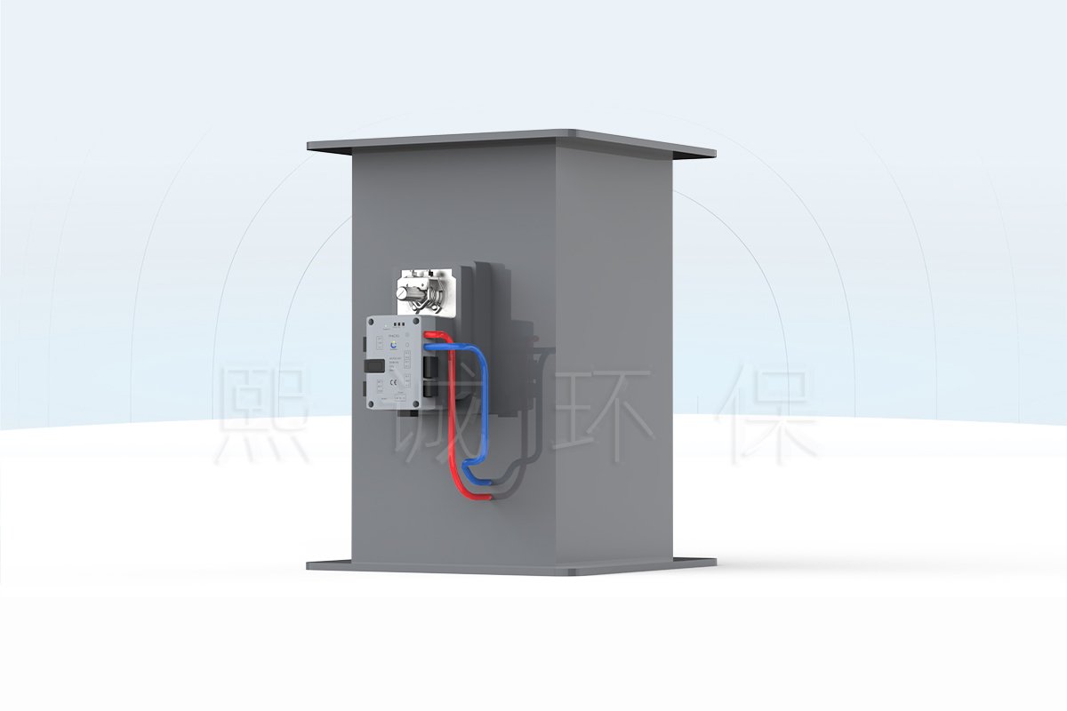
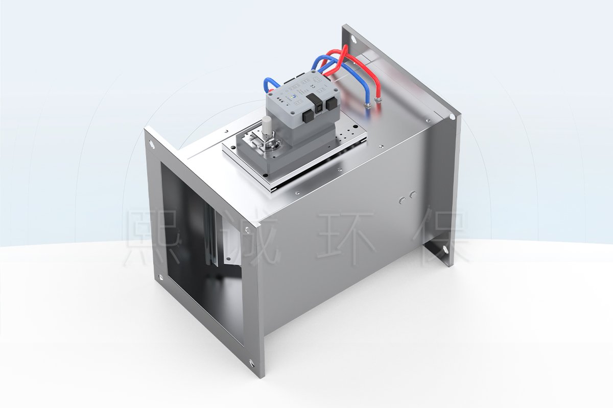
The rectangular VAV butterfly damper regulates air through a rectangular duct by rotating a blade inside a flanged body. It is made to the project’s width and height rather than selected from a round nominal diameter. XICHENG supplies PP, galvanized-steel and stainless-steel configurations, allowing the body material and exposed components to be reviewed against the supply or exhaust air stream.
The physical damper can be supplied by itself, with an actuator, or as part of a measured control assembly. In the measured configuration, a central differential-pressure pickup and airflow sensor provide the feedback used by the controller to move the blade toward the requested airflow. A separate pressure-control sequence can also use the damper to correct room or zone differential pressure. These functions depend on the selected sensor, controller, actuator and commissioning values; the damper body alone does not create closed-loop control.
Product Selection Summary
Choose This Rectangular Damper When
- The duct opening is defined by width W and height H and requires a motorized butterfly blade rather than a circular valve body.
- The project needs PP, galvanized-steel or stainless-steel construction selected for the actual supply or exhaust air stream.
- Minimum, normal, maximum and emergency airflow can be defined for each valve tag.
- The controls design can distinguish a simple position command from measured airflow or room-pressure feedback.
- The installation has enough straight duct, actuator clearance and service access for the selected measurement and control package.
Select Another Product When
Use a round VAV butterfly damper when the duct connection is circular. Evaluate a VAV Venturi air valve when the specification calls for a Venturi body and its associated pressure-response mechanism. A fume hood that needs face-velocity or sash-position control should be evaluated as a complete fume hood VAV control damper package instead of selecting this page by duct shape alone.
This product is not a fire damper, smoke damper, passive backdraft damper, liquid-service butterfly valve or certified isolation damper. It also does not replace the fan, airflow sensor, room-pressure sensor, fume hood controller, balancing work or site acceptance testing required by the ventilation system.
Information Required for Configuration
For each damper tag, provide the duct width and height, material, air-stream description, minimum and maximum airflow, available pressure, installation orientation and usable straight length. If the quotation includes control components, also provide power, command and feedback signals, BMS protocol, room-pressure or airflow sequence, fail position, alarm requirements and the expected response time. XICHENG uses these fields to identify the damper body, shaft arrangement, actuator torque, measurement method and supplied control scope.
Key Specifications and Rectangular Size Arrangement
Start with the rectangular duct opening and the required airflow points, then select the body material and control package. Standard rectangular configurations use the dimensions shown below, while the production drawing defines the final W x H opening, shaft support, flange holes and actuator clearance for the ordered damper.
Available Specifications
| Selection Item | Available Configuration | Selection Requirement |
|---|---|---|
| Product type | Rectangular variable-air-volume butterfly damper | For rectangular laboratory and HVAC ductwork |
| Body materials | Flame-retardant PP, galvanized steel or stainless steel | Confirm the complete exposed assembly against the air stream |
| Nominal connection | Made-to-order rectangular width W x height H | Specify the required clear opening and mating flange pattern |
| Standard flange width | 40 mm | 50 mm for the VAV-Q sizes below; alternative connections are available on request |
| Standard body length | 400 mm | Does not include every actuator, controller or service envelope |
| Airflow sizing method | Calculated from the clear duct area and design velocity; the table compares airflow at 1, 6 and 10 m/s | Final controllable range depends on size, pressure, pickup and controller configuration |
| Measurement option | Central differential-pressure/Pitot-style pickup with airflow sensor | Included only in the selected measured-control package |
| Available control modes | Airflow control or zone differential-pressure control | Requires the applicable sensor, controller, actuator and commissioning sequence |
| Supply options | Body-only, actuator-equipped or measured closed-loop assembly | Select the required actuator, sensor, controller and communication functions when ordering |
Rectangular VAV-Q Size and Airflow Table
The VAV-Q schedule links each rectangular clear opening to a 50 mm flange width, 400 mm body length and calculated airflow at three duct velocities. Use a complete row when comparing sizes because each airflow range is calculated for that specific width and height.
| Model | Internal Width W (mm) | Internal Height H (mm) | Flange Width G (mm) | Body Length (mm) | Airflow (m³/h) | ||
|---|---|---|---|---|---|---|---|
| v = 1 m/s | v = 6 m/s | v = 10 m/s | |||||
| VAV-Q160×160 | 160 | 160 | 50 | 400 | 92 | 553 | 922 |
| VAV-Q200×160 | 200 | 160 | 50 | 400 | 86 | 518 | 864 |
| VAV-Q200×200 | 200 | 200 | 50 | 400 | 115 | 691 | 1152 |
| VAV-Q250×160 | 250 | 160 | 50 | 400 | 144 | 864 | 1440 |
| VAV-Q250×200 | 250 | 200 | 50 | 400 | 144 | 864 | 1440 |
| VAV-Q320×160 | 320 | 160 | 50 | 400 | 180 | 1080 | 1800 |
| VAV-Q320×200 | 320 | 200 | 50 | 400 | 184 | 1106 | 1843 |
| VAV-Q320×250 | 320 | 250 | 50 | 400 | 230 | 1382 | 2304 |
| VAV-Q400×200 | 400 | 200 | 50 | 400 | 288 | 1728 | 2880 |
| VAV-Q400×250 | 400 | 250 | 50 | 400 | 288 | 1728 | 2880 |
| VAV-Q500×250 | 500 | 250 | 50 | 400 | 360 | 2160 | 3600 |
| VAV-Q630×250 | 630 | 250 | 50 | 400 | 450 | 2700 | 4500 |
The selected material, free area, airflow range, operating pressure, sensor range and actuator package are matched to each application. Include these operating conditions in the inquiry so the supplied assembly can be sized as one control package.
How W x H, Body Length and Actuator Clearance Are Defined
W and H identify the clear rectangular duct opening. The complete installation envelope also includes the flanges, blade shaft, linkage, actuator, sensor tubes and controller enclosure. Supports, insulation and adjacent fittings must remain outside the actuator movement and service area.
Airflow cannot be selected from width alone. Calculate the required duct area from the scheduled flow and design velocity, then check that the blade, pickup and controller can measure and regulate the full operating range at the available pressure. Very low velocity can weaken the differential-pressure signal, while excessive velocity can increase pressure loss and noise.
PP Rectangular Configuration Drawing
The PP drawing shows the flanged body, central blade/shaft arrangement and the external space occupied by the actuator and control components. Review it before locating a wall penetration, duct support or adjacent elbow.
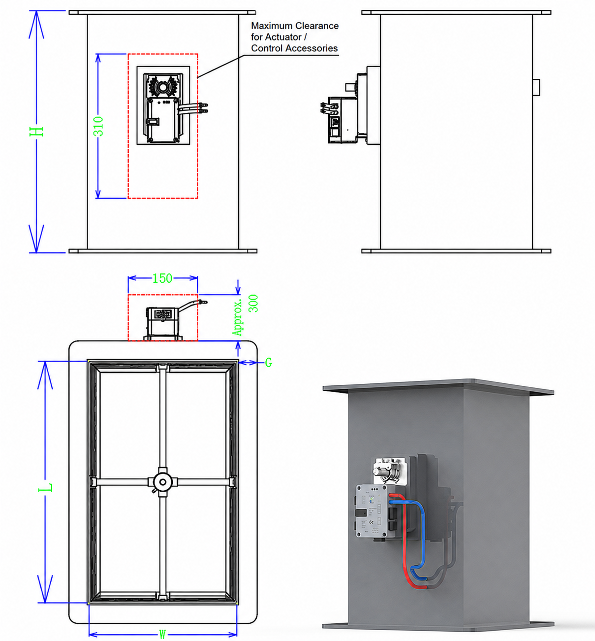
The PP configuration drawing shows an actuator and controller envelope of approximately 150 x 300 mm. Because the external envelope changes with the opening and control package, provide the required duct W x H and available installation space when requesting a drawing.
Metal Rectangular Configuration Drawing
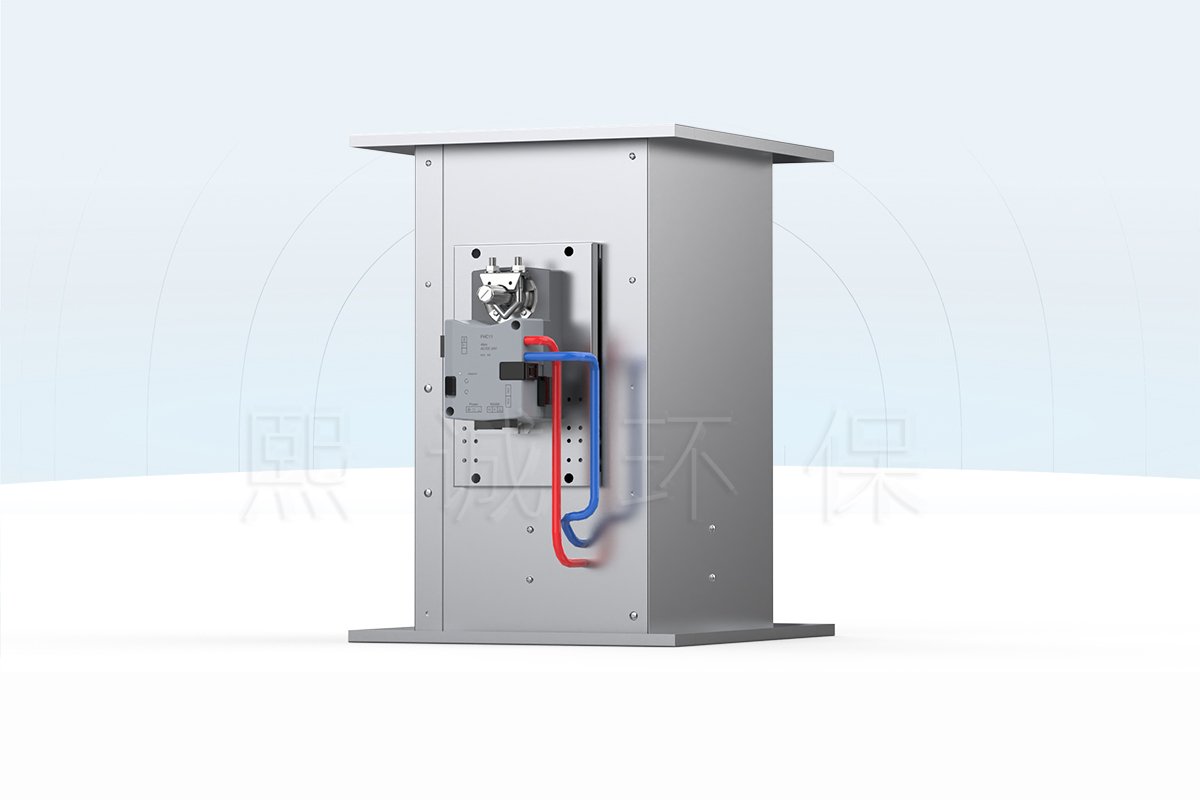
The stainless-steel drawing uses a different casing and actuator-mount arrangement. It shows why a metal rectangular damper should not inherit the PP body drawing even when both serve the same airflow range.
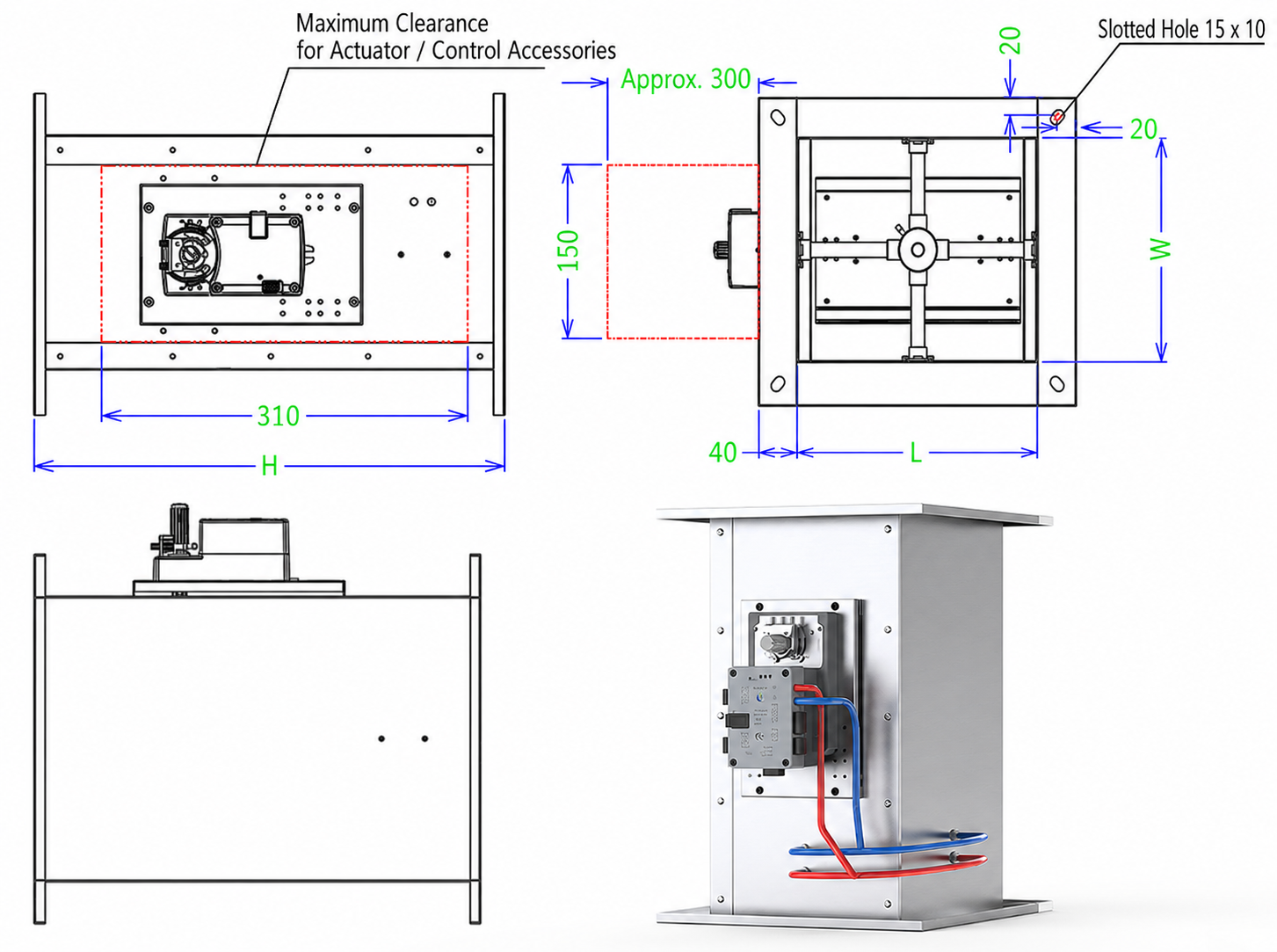
The metal configuration drawing shows an actuator/control mounting area of approximately 310 x 150 mm and slotted flange holes. Provide the selected material, W x H, body length, mating-hole pattern and preferred controller location so these details can be included in the production drawing. Do not scale dimensions from the image.
Construction, Materials and Airflow Principle
A rectangular VAV damper must be specified as an assembly, not by body material alone. The casing, blade, shaft, bearings, seals, fasteners, measurement tubes and actuator mount can see different combinations of the air stream, condensation and mechanical load. The final material schedule should identify each exposed component that matters to the application.
PP, Galvanized-Steel and Stainless-Steel Configurations
The PP configuration uses a flame-retardant polypropylene body for laboratory exhaust applications that require polymer construction. Select it against the actual chemicals, concentrations, temperature and possible condensate, and include the shaft, fasteners, seals, pressure tubing, sensor and actuator enclosure in the compatibility check.
Galvanized steel is the general-purpose metal option for supply air and non-corrosive exhaust where a fabricated rectangular body is preferred. Stainless steel is available where the specification or air stream calls for a stainless body. State the required stainless grade and finish in the inquiry so they can be included in the material schedule and production drawing.
| Body Option | Good Starting Point | Confirm Before Ordering |
|---|---|---|
| Flame-retardant PP | Laboratory exhaust where a polymer casing is preferred | Chemical list, concentration, temperature, condensate and every exposed component |
| Galvanized steel | General supply air or non-corrosive exhaust | Humidity, coating damage risk, cleaning method and project corrosion category |
| Stainless steel | Specified stainless duct systems and duties requiring a stainless body | Steel grade, finish, welding, fasteners, seals and air-stream compatibility |
How the Butterfly Blade Regulates Airflow
The actuator rotates the blade about its shaft. As the blade moves away from the open position, it reduces the free area and increases resistance through the rectangular duct section. This changes airflow only because the fan and duct system provide a pressure difference across the damper. The damper does not generate airflow and cannot correct an undersized fan, blocked duct or unstable upstream control loop.
A position-only configuration repeats a commanded blade angle. That approach can be suitable when the system designer has a separate airflow measurement or only needs a defined open/closed or proportional position. It is not equivalent to measured VAV control because the same blade angle can produce different airflow when fan pressure, filters or other branch dampers change.
What the Differential-Pressure Pickup Adds
The measured configuration uses a central Pitot-style pressure pickup to create a differential-pressure signal related to velocity through the damper section. An airflow sensor reads that signal, the controller compares measured flow with the setpoint, and the actuator changes blade position to reduce the difference. For zone-pressure control, the controller instead responds to the selected differential-pressure signal and moves the same blade to correct the pressure relationship.
Measurement quality depends on the pickup orientation, clean tubing, sensor range, airflow profile and configured duct area. An elbow, transition or obstruction placed too close to the pickup can distort the velocity profile. The commissioning procedure must therefore check both the mechanical movement and the measured result at the installed condition.
Actuation, Measurement and Control Integration
Select the control level before finalizing the enclosure and wiring. A body-only rectangular damper provides the blade and shaft. An actuator-equipped assembly adds commanded movement. A measured-control assembly adds the pickup, airflow or pressure sensor, controller, feedback and commissioned setpoints needed for a closed loop.
Body-Only, Actuator-Equipped and Measured-Control Configurations
| Configuration | What It Provides | Information Needed for Selection |
|---|---|---|
| Damper body | Rectangular casing, butterfly blade, shaft and mounting interface | Actuator, command, measurement, feedback and control sequence |
| Actuator-equipped damper | Blade movement from an electrical command | Whether position is sufficient or an external airflow loop is required |
| Measured airflow package | Differential-pressure pickup, sensor, controller, actuator and airflow feedback | Airflow points, available pressure, calibration and acceptance tolerance |
| Zone-pressure package | Controller and actuator respond to the selected pressure signal | Reference space, pressure setpoint, door-delay logic and fail sequence |
Control Signals and Communication
Available control hardware supports one analog input and one analog output configured for 2-10 VDC or 4-20 mA. The input can carry an airflow setpoint, pressure setpoint or blade-position command according to the selected operating mode. The output can report measured airflow, differential pressure or position. Define one clear function and engineering unit for each signal in the control point list.
Modbus RTU is available for BMS communication, and ZPC211 configurations can also support BACnet MS/TP. Network communication provides commands, values and status points but does not replace power wiring, sensor tubing or commissioning. Specify the protocol, baud rate, addressing, writable setpoints, feedback units and alarm ownership before panel production.
QAVC10-R and ZPC211 Control Options
| Controller/Actuator | Electrical Data | Actuation | Control Use |
|---|---|---|---|
| QAVC10-R | 24 VDC +/-10%, 17 W max; 24 VAC +/-10%, 38 VA max | 5 or 10 Nm; 2, 5 or 9 s for 90 degrees | Fast measured airflow or pressure-control configuration |
| ZPC211 | 24 VDC +/-10%, 5 W max; 24 VAC +/-10%, 9 VA max | 5, 15 or 30 Nm; 60 s for 90 degrees | Airflow or differential-pressure configuration with controller-dependent BMS options |
A complete measured-airflow configuration can be selected for airflow error within +/-5% when the pickup, sensor, controller, duct area and operating range are matched and commissioned together. This performance target applies to the configured closed-loop assembly, not to a body-only damper.
Choose actuator torque from blade area, seal friction, shaft arrangement and operating pressure. Choose travel time from the system sequence rather than assuming faster is always better. A fast actuator may be necessary for fume hood or room-pressure response, while a slower actuator can be appropriate where stable modulation and equipment life are the priority.
Applications, Selection and RFQ Inputs
The rectangular VAV damper fits rectangular laboratory supply, general exhaust, make-up air, room supply/exhaust tracking and local equipment exhaust branches. For chemical exhaust, select the body and every exposed component for the actual chemical, concentration, temperature and possibility of condensate.
Suitable Laboratory and HVAC Duties
For supply air, the principal decisions are usually duct area, acceptable velocity, available pressure, noise target and control response. Galvanized steel can be the starting body option when the air is non-corrosive. For general laboratory exhaust, stainless steel or PP may be considered according to the chemical and cleaning environment. The final selection must also account for the blade, shaft, seals, pickup tubes and actuator location.
For room airflow tracking, one measured damper can regulate a supply or exhaust branch while the room controller coordinates the required offset between total supply and total exhaust. For room-pressure control, the pressure sensor location and reference space are as important as the valve. Door opening logic, alarm delays and fail positions must be part of the sequence so that the actuator does not react to every short pressure disturbance.
A fume hood exhaust branch can use a rectangular damper, but duct shape alone does not define a fume hood control system. Face-velocity sensing, sash input, emergency exhaust, hood alarms and room-airflow coordination belong to the fume hood VAV control damper configuration.
Material and Component Compatibility Review
List the chemicals that may enter the duct, their expected concentration, temperature and physical state, and whether condensation or droplets are possible. Include both direct-contact and indirect-contact components in the compatibility check. A PP casing can still contain metal shafts or fasteners, while a stainless casing can include non-metal seals, tubing and an external controller. Specify these details in the material schedule before fabrication.
Do not select galvanized steel only from a cost comparison when the branch carries corrosive vapor. Do not select stainless steel only from the generic material name when the project requires a specific grade. Do not select PP without checking temperature, structural span and external fire requirements. Each body option solves a different part of the application, not every project condition.
Rectangular VAV Damper Sizing Sequence
- Confirm the duct width W and height H at the intended valve location.
- List minimum, normal, maximum and emergency airflow for that branch.
- Calculate velocity at each airflow point and compare it with the 1-10 m/s sizing range shown in the airflow table.
- State the pressure available across the damper at minimum and maximum system demand.
- Select body and component materials from the air-stream review.
- Choose body-only, actuator-equipped, measured airflow or zone-pressure control scope.
- Confirm torque, travel time, power, signal, BMS and fail-position requirements.
- Review the final W x H drawing, flange holes, body length, shaft support and actuator service envelope.
If the calculated operating range produces an unreliable low differential-pressure signal, the answer is not to assume better accuracy. Review the damper area, measurement method, sensor range or control architecture. The selected configuration must provide a usable measurement signal over the required turndown.
Information Needed for a Project Quotation
Send the valve schedule or a tag-by-tag list with application, W x H, material, minimum and maximum airflow, available pressure, air-stream chemistry, temperature, installation orientation and quantity. For controlled assemblies, include actuator power, analog signal type, BMS protocol, sensor ownership, control sequence, fail position, alarm points and required response. Attach the duct layout, equipment schedule, control schematic and point list when available.
XICHENG will return the selected body configuration, actuator and control package, supplied measurement components, connection drawing and applicable performance data. The quotation and drawing will clearly identify what is included with each damper tag.
Installation, Commissioning and Maintenance
Install the rectangular VAV damper so the casing remains square and the blade can travel without rubbing or binding. A distorted flange can change shaft alignment and actuator load even when the duct opening still appears correct. Support the adjacent duct independently and match the mating ductwork to the supplied flange-hole pattern.
Duct and Clearance Checks
Orient the central pressure pickup as shown on the project drawing and preserve the straight duct needed to produce a representative airflow profile. Avoid placing a sharp elbow, transition, branch take-off or obstruction immediately against the measurement section. Where site space is limited, document the actual upstream and downstream arrangement so the measurement and acceptance method can be adjusted before commissioning.
Leave access to the actuator, linkage, controller enclosure, wiring terminals and pressure tubes. The PP and metal drawings show different external envelopes; insulation, wall penetrations, cable tray and supports must be coordinated with the selected version. Protect the controller from condensate and keep pressure tubing free from kinks, trapped liquid and reversed high/low connections.
Airflow Measurement and Control Commissioning
Before power is applied, move the blade through its full mechanical stroke and confirm the commanded direction, open and closed positions, and any fail-state action. Verify supply voltage, analog signal scaling, communication address and point names. For a measured airflow package, check tubing polarity and enter the correct rectangular area or configuration data required by the controller.
Commission at minimum, normal and maximum airflow rather than at one point. Compare the controller value with an agreed field measurement method, record available pressure and observe stability after setpoint changes. For room-pressure control, test occupied and unoccupied sequences, door events, supply/exhaust tracking, alarms and recovery time. Acceptance should be based on measured system behavior, not actuator movement alone.
Inspection and Maintenance
Inspect the blade and casing for deposits, corrosion or impact damage; check shaft support, fasteners, seals, linkage and actuator attachment; and confirm that pressure ports and tubing remain clear. Cleaning materials must be compatible with the selected PP, galvanized or stainless construction and with non-metal components. Recheck airflow or pressure calibration after sensor replacement, controller replacement, major duct changes or any work that alters the measurement section.
Related Laboratory Air Dampers
The Round VAV Butterfly Damper serves circular ducts with flange or socket connections. The Duct Airflow Control Damper combines measured airflow or pressure control with external system integration. The Fume Hood VAV Control Damper adds hood-specific face-velocity, sash and emergency-control functions.
Evaluate the VAV Air Damper with Explosion-Proof Actuator when the hazardous-area review applies to the actuator package. Evaluate a VAV Venturi Air Valve when the project specifies a Venturi mechanism rather than a butterfly blade. Certification or pressure-response requirements cannot be transferred between these product families.
Frequently Asked Questions
Is a rectangular VAV damper pressure independent?
The body alone is not pressure independent. A measured closed-loop package can correct blade position when the measured airflow departs from its setpoint, provided the sensor, controller, actuator and available pressure are suitable for the selected operating range. Confirm that control behavior for the supplied configuration rather than applying the term to every rectangular damper.
Can the same page specification be used for PP and metal bodies?
No. PP, galvanized-steel and stainless-steel configurations share the same airflow-control function but use different fabrication, shaft support and actuator-mount details. Use the drawing and component schedule supplied for the selected body material. Do not transfer dimensions from one material configuration to another.
Can actuator position be used as measured airflow?
Actuator position shows blade angle, not airflow. Actual airflow also changes with fan pressure, duct resistance, filters and other dampers. Use a differential-pressure pickup or another accepted airflow measurement when the control or acceptance requirement is stated in airflow units.
Which dimensions are needed for a quotation?
Provide the clear duct width W and height H, available body length, flange or mating-hole requirements, installation orientation and clearance around the actuator side. Also state whether the dimensions refer to the duct opening, outside casing or an existing flange so the drawing does not inherit an ambiguous symbol.
When should a Venturi air valve be evaluated?
Evaluate a Venturi air valve when the specification requires a Venturi body, the project is designed around that response mechanism, or an existing Venturi valve schedule must be matched. Use the rectangular butterfly damper when rectangular duct geometry and a rotating blade are the intended construction.
Can this product be used as a fire or smoke damper?
No. This rectangular VAV damper is not a fire damper or smoke damper. Where the duct crosses a rated barrier or the life-safety design requires a certified fire or smoke damper, specify that device separately and coordinate it with the airflow-control damper.
Contact the Xicheng Engineering Team Today
Send the rectangular duct W x H, airflow schedule, available pressure, selected material, air-stream description and control schematic. For a measured-control assembly, include power, command and feedback signals, BMS protocol, fail position and required response. XICHENG will use this information to prepare a product configuration, connection drawing and quotation for review.
Shenzhen Office: No. 34 Zhenxing Road (Shengtaian Heavy Industrial Park B), Loucun, Guangming New Dist, Shenzhen, Guangdong, China
WhatsApp: +86 181 2647 8161
Engineering Mailbox: fanalax34@gmail.com