


Description
Round VAV Damper for Laboratory Airflow Control
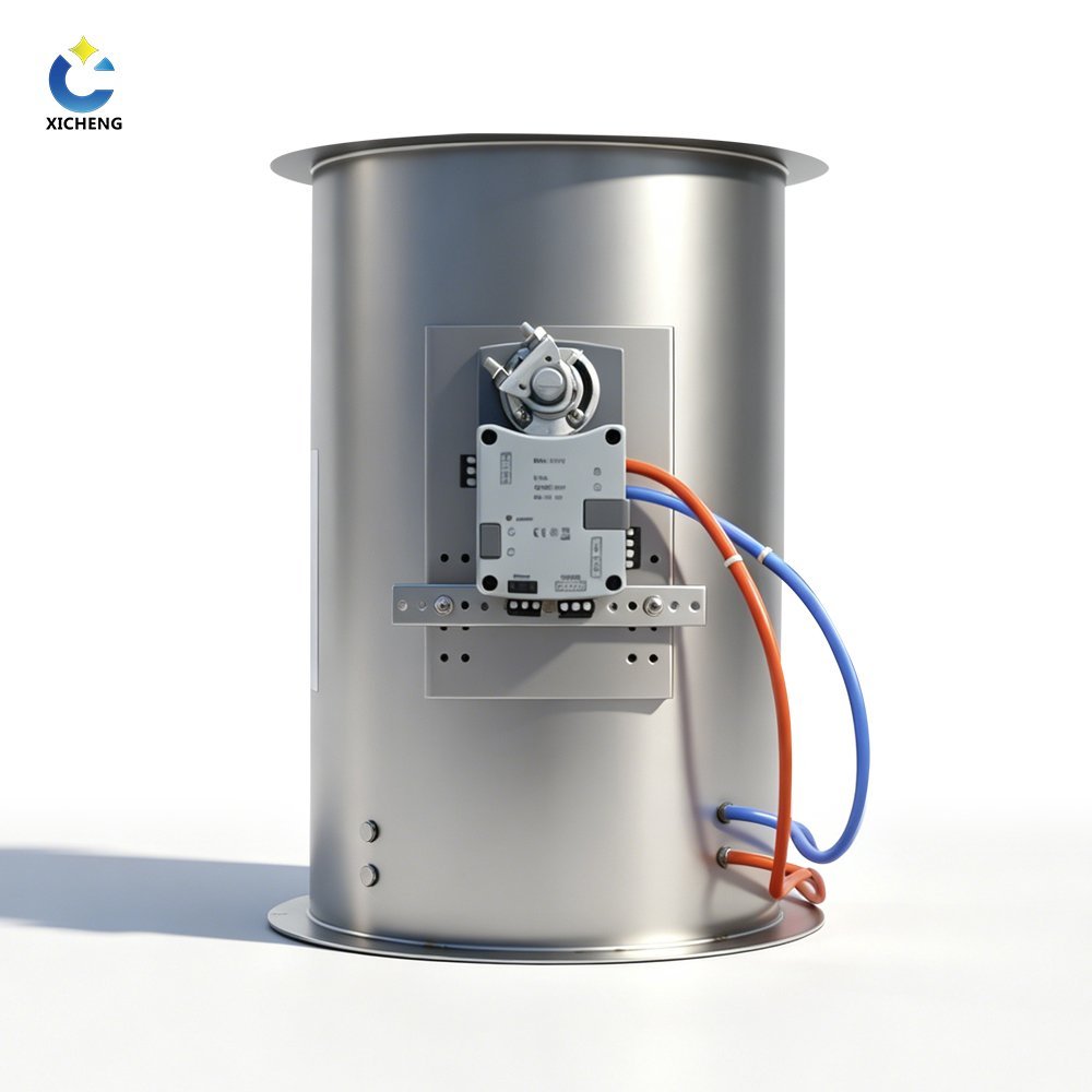
The round VAV butterfly damper regulates airflow in circular laboratory ductwork by rotating a blade through a commanded angle. PP, galvanized-steel and stainless-steel bodies cover different air-stream and construction requirements, while flanged and socket connections allow the damper to match new or existing round ductwork.
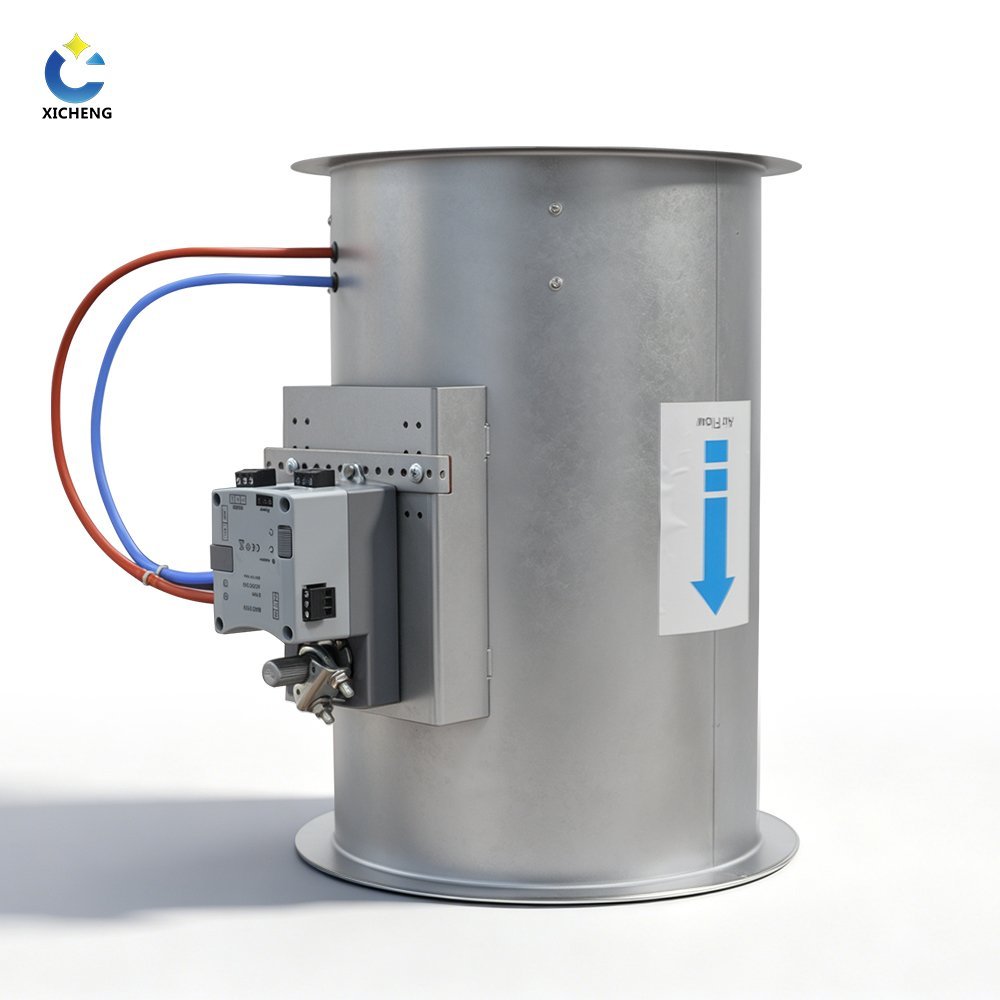
The required control function determines what is supplied around the damper body. A body-only unit provides the casing, blade and shaft for mechanical balancing or connection to controls supplied elsewhere. An actuator-equipped unit adds powered positioning and the specified command or position feedback. A closed-loop VAV assembly adds airflow measurement and a controller so blade position can change in response to measured airflow rather than position command alone.
This distinction matters when comparing quotations. Two round dampers with the same diameter can have different materials, connections, actuator speeds, sensor ranges and communication functions. They may also serve different duties: stable proportional positioning, fast fume hood exhaust response, duct airflow regulation or room supply/exhaust tracking. Define the operating points and control sequence before selecting the final configuration.
Product Selection Summary
Choose This Product When
- The duct is round and the application requires variable airflow through a rotating butterfly blade.
- The project needs PP, galvanized-steel or stainless-steel construction selected against the actual air stream.
- A flange or socket connection can be coordinated with the duct and installation space.
- The control design defines the airflow range, available pressure, actuator, measurement method and feedback signal.
- The damper will serve laboratory supply air, general exhaust, fume hood exhaust or room airflow control after application review.
Choose Another Product When
Use a rectangular VAV butterfly damper for a width-by-height duct opening. Use a VAV Venturi air valve when the specification calls for a Venturi body and its corresponding control mechanism. This product is not a fire damper, smoke damper, passive backdraft damper, liquid butterfly valve or certified isolation valve.
Do not select this damper only because the maximum airflow fits one table row. The minimum controllable airflow, available pressure and sensor signal are equally important. An oversized damper can produce weak measurement at low flow and concentrate useful control into a small blade-angle range, while an undersized damper can add pressure loss and noise at maximum or emergency exhaust.
For each damper tag, provide the minimum, normal, maximum and emergency airflow together with the available pressure, material, diameter and connection. Add the required actuator, control signal, feedback and BMS interface when ordering a powered or closed-loop configuration.
Key Specifications, Sizes and Airflow Data
Match the round VAV damper to the material, duct diameter, connection, airflow range and available pressure before selecting the actuator or controller. The six PP sizes and the larger metal sizes use different connection dimensions, so each material should be ordered from its corresponding table and production drawing.
Key Product Specifications
| Selection Item | Available Configuration | Selection Requirement |
|---|---|---|
| Product type | Round variable air volume butterfly damper | For circular laboratory ductwork |
| Body materials | Flame-retardant PP, galvanized steel or stainless steel | Final grade, exposed parts and finish follow the selected air stream and project specification |
| PP construction | One-piece molded body, 5 mm wall, reinforced flange, PP plus glass-fiber blade and silicone covering | These details apply to the PP configuration only |
| Round connection | Flanged or socket arrangement | Socket forms are available for D110, D125, D160 and D200 |
| PP internal diameters | 110, 125, 160, 200, 250 and 315 mm | Use the PP size table and supplied connection drawing |
| Supply options | Body-only, actuator-equipped or measured closed-loop control package | The quotation identifies the included actuator, sensor, controller and accessories |
| Airflow measurement | In-body or side pressure pickup with the applicable closed-loop package | Blade position alone is not an airflow measurement |
| Compatible control paths | QAVC10 for duct/room control or FHC10 for fume hood control | Performance, signals and sequence depend on the selected package |
PP Round Sizes and Airflow Data
The table below lists PP round dimensions in millimetres and calculated airflow in cubic metres per hour (CMH). Select the diameter from the required airflow, design velocity and available pressure rather than matching the duct connection alone.
| Model | Flange OD D1 | Internal Diameter D | Overall Length L | Socket Depth L1 | Airflow (CMH) | ||
|---|---|---|---|---|---|---|---|
| v = 1 m/s | v = 6 m/s | v = 10 m/s | |||||
| VAV-R/110 | 185 | 110 | 240 +/- 3 | 25 | 34 | 205 | 342 |
| VAV-R/125 | 200 | 125 | 240 +/- 3 | 25 | 44 | 265 | 441 |
| VAV-R/160 | 240 | 160 | 280 +/- 3 | 30 | 72 | 434 | 723 |
| VAV-R/200 | 280 | 200 | 300 +/- 3 | 30 | 113 | 678 | 1130 |
| VAV-R/250 | 339 | 250 | 363 +/- 3 | 40 | 100 | 968 | 1600 |
| VAV-R/315 | 395 | 315 | 423 +/- 3 | 53 | 150 | 1579 | 2400 |
How to Use the Airflow Values
The three velocity columns allow direct comparison between PP round sizes. Because the 1 m/s entries for VAV-R/250 and VAV-R/315 do not follow the same proportional relationship as the higher-velocity entries, include the required low-flow point in the inquiry before selecting either size.
State minimum, normal, maximum and emergency airflow together with the pressure available at the damper location. The controller, sensor and actuator can then be matched to the required operating range and response.
Metal Round Flange Dimensions
Metal round configurations use a 25 mm flange edge width and 9 mm bolt holes. The compact table pairs smaller and larger diameters to reduce page length while preserving every available hole count and bolt-circle dimension. These dimensions apply to the fabricated metal body, not the molded PP body.
| Diameter | Holes | Bolt Circle | Diameter | Holes | Bolt Circle |
|---|---|---|---|---|---|
| Ø100 mm | 4 | Ø130 mm | Ø600 mm | 14 | Ø630 mm |
| Ø125 mm | 4 | Ø155 mm | Ø650 mm | 14 | Ø680 mm |
| Ø150 mm | 6 | Ø180 mm | Ø700 mm | 16 | Ø730 mm |
| Ø160 mm | 6 | Ø190 mm | Ø750 mm | 18 | Ø780 mm |
| Ø200 mm | 6 | Ø230 mm | Ø800 mm | 18 | Ø830 mm |
| Ø250 mm | 6 | Ø280 mm | Ø850 mm | 20 | Ø880 mm |
| Ø300 mm | 8 | Ø330 mm | Ø900 mm | 20 | Ø930 mm |
| Ø315 mm | 8 | Ø345 mm | Ø950 mm | 22 | Ø980 mm |
| Ø350 mm | 8 | Ø380 mm | Ø1000 mm | 22 | Ø1030 mm |
| Ø400 mm | 10 | Ø430 mm | Ø1050 mm | 24 | Ø1080 mm |
| Ø450 mm | 12 | Ø480 mm | Ø1100 mm | 24 | Ø1130 mm |
| Ø500 mm | 12 | Ø530 mm | Ø1150 mm | 26 | Ø1180 mm |
| Ø550 mm | 14 | Ø580 mm | Ø1200 mm | 26 | Ø1230 mm |
Metal Round Airflow Range
The listed metal round configurations use a 400 mm body length. The paired table keeps all diameter and airflow combinations visible without repeating the same body length in every row. Select the final airflow range together with the available pressure, actuator torque and measurement package.
| Diameter | Airflow (m³/h) | Diameter | Airflow (m³/h) |
|---|---|---|---|
| Ø100 mm | 28–283 | Ø650 mm | 1195–11946 |
| Ø125 mm | 44–442 | Ø700 mm | 1385–13854 |
| Ø150 mm | 64–636 | Ø750 mm | 1590–15904 |
| Ø160 mm | 72–724 | Ø800 mm | 1810–18095 |
| Ø200 mm | 113–1131 | Ø850 mm | 2043–20428 |
| Ø250 mm | 177–1767 | Ø900 mm | 2290–22902 |
| Ø300 mm | 254–2545 | Ø950 mm | 2552–25517 |
| Ø315 mm | 281–2805 | Ø1000 mm | 2827–28274 |
| Ø350 mm | 346–3464 | Ø1050 mm | 3117–31172 |
| Ø400 mm | 452–4524 | Ø1100 mm | 3421–34211 |
| Ø450 mm | 573–5725 | Ø1150 mm | 3739–37392 |
| Ø500 mm | 707–7068 | Ø1200 mm | 4071–40714 |
| Ø550 mm | 855–8553 | Ø1250 mm | 4418–44177 |
| Ø600 mm | 1018–10178 | — | — |
Flanged and Socket Connection Arrangements
Socket Connection and Service Envelope
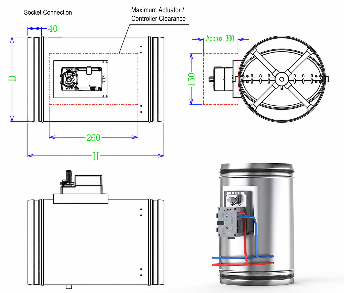
The socket drawing identifies the engagement geometry and the side envelope occupied by the actuator or controller. Allow space for the complete assembly, wiring, pressure tubing and service access; the nominal duct diameter does not describe this external envelope.
Flanged Connection and Service Envelope
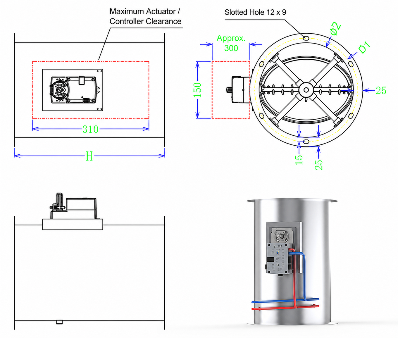
For a flanged connection, check D1, the mating flange geometry and the slotted-hole arrangement on the supplied drawing. Keep the controller side accessible and avoid placing adjacent ductwork, insulation or supports inside the indicated service envelope.
Construction, Material Options and Operating Principle
The material selection applies to the complete air-stream path, not only the visible body. Review the blade, shaft, seals, fasteners and pressure pickup together with the casing whenever the damper handles chemical exhaust or condensate.
PP Air-Stream Construction
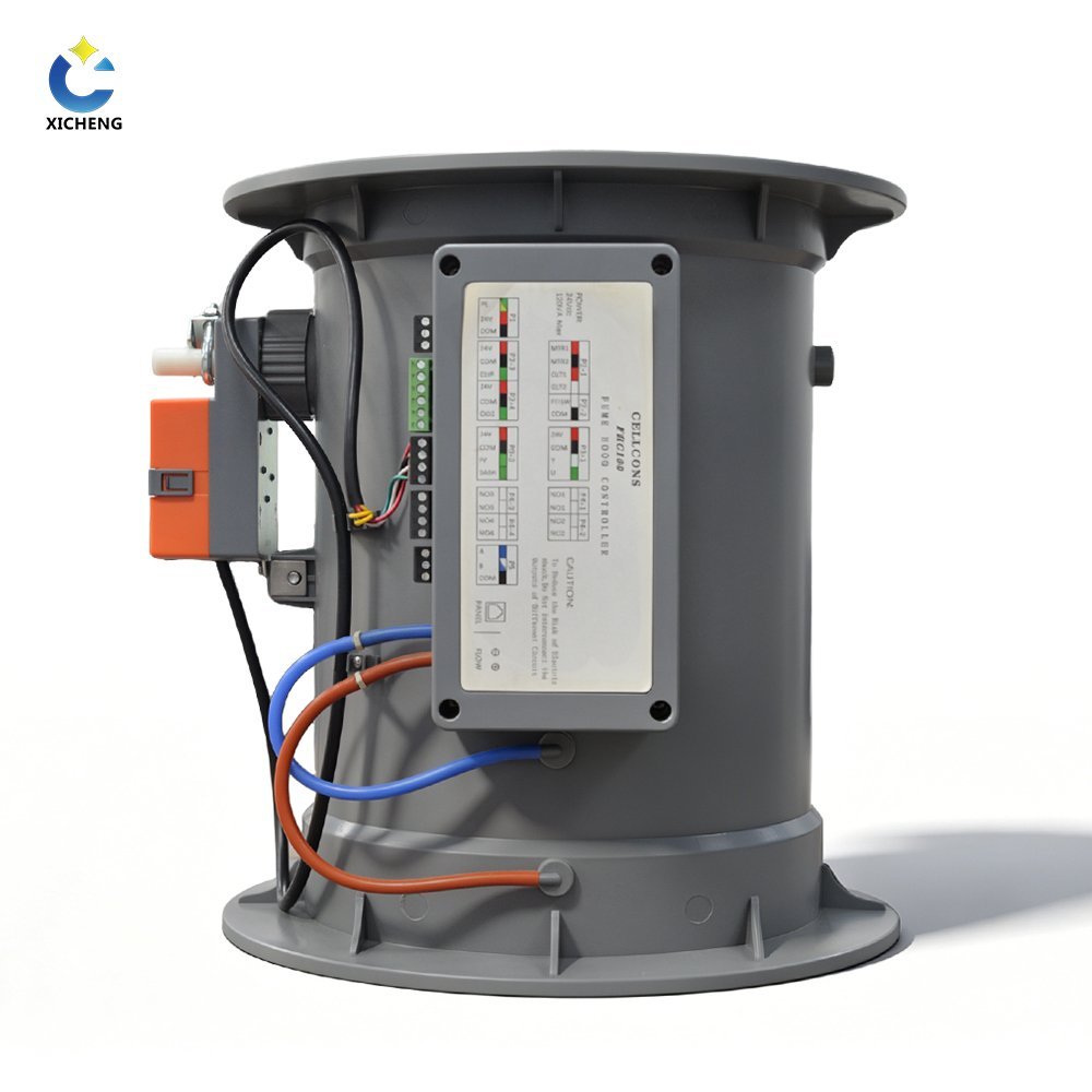
The PP configuration uses a one-piece molded flame-retardant polypropylene body with a 5 mm wall and reinforced flange. Its butterfly blade is glass-fiber-reinforced PP with a silicone covering. V2 flame-retardant PP is the standard body material, while V0 can be configured when required.
PP is selected for laboratory exhaust only after the chemical list, concentration, normal and upset temperature, condensate and cleaning method are reviewed. A PP body does not make every exposed component universally compatible, so the quotation should identify the materials used for the shaft, seals, pressure pickup and actuator-side hardware.
The one-piece molded body reduces fabricated casing joints in the air-stream path, but the complete installation still includes a duct joint, blade shaft and external operating components. Where corrosive condensate is possible, state the mounting orientation and drainage conditions. The actuator and controller should remain outside direct chemical contact and protected from liquid entering through pressure tubing or the duct connection.
Galvanized-Steel and Stainless-Steel Options
Galvanized-steel and stainless-steel VAV dampers are available for projects that require a metal body. Galvanized steel is generally considered for non-corrosive supply or exhaust service where the coating and environmental exposure are acceptable. Stainless steel is evaluated where the specification, cleaning method or air-stream condition requires a stainless construction.
Galvanized-steel and stainless-steel bodies are made to order. Specify the sheet construction, stainless grade or coating, finish, blade, shaft, seals and connection requirements in the inquiry. Use the metal size and flange tables for these bodies because the molded PP dimensions do not apply to metal construction.
Metal selection should also account for external conditions. A supply-air damper above a clean ceiling faces a different corrosion and cleaning environment from an exhaust damper installed outdoors or near a scrubber. If the branch can carry droplets, aggressive cleaning agents or high humidity, include those conditions instead of selecting a body from the word “stainless” or “galvanized” alone.
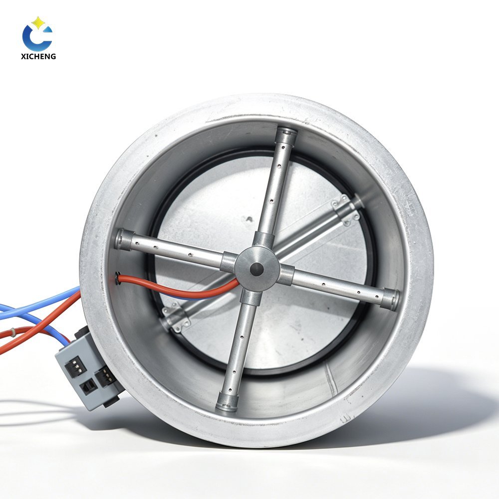
How the Butterfly Blade Regulates Airflow
A command moves the actuator, the actuator rotates the shaft, and the shaft changes the butterfly blade angle. As the opening changes, the damper changes resistance in the duct branch. The resulting airflow also depends on fan operation, duct resistance and the pressure available at the damper.
A body-only damper can therefore be positioned or balanced, but it cannot maintain a verified airflow by itself when system pressure changes. Closed-loop VAV control adds an airflow measurement, compares the measured value with the setpoint and adjusts blade position until the accepted control condition is reached.
Blade Position Is Not Measured Airflow
Position feedback confirms where the actuator or blade is commanded to be; it does not prove the volume of air passing through the duct. The same angle can produce different airflow after fan speed, filter resistance or another branch condition changes. Projects that require airflow control need a defined measurement method and site commissioning at the required operating points.
The relationship between blade angle and airflow also becomes nonlinear near the closed position. Small movements can cause a large percentage change in free area, particularly when the damper is oversized for the minimum duty. Closed-loop control reduces this dependence on a fixed angle, but it still requires enough pressure authority and a measurable airflow signal across the intended range.
Actuator, Measurement and Control Interfaces
Select the required control level before choosing the actuator. The round VAV damper is available as a mechanical body, an actuator-equipped damper or a closed-loop airflow-control assembly. These configurations use the same blade mechanism but provide different signals and control functions.
Body-Only, Actuator-Equipped and Closed-Loop Options
A body-only assembly includes the damper mechanism and selected connection. An actuator-equipped assembly adds powered blade movement, command input and the specified position feedback or end status. A closed-loop package also includes the airflow measurement and controller needed to compare actual airflow with the setpoint.
For each damper tag, identify power, torque, rotation time, command range, feedback, manual override and the required position after power or signal loss. If measured airflow is required, also define the sensor, pressure pickup, engineering units, accepted accuracy and commissioning method.
Actuator torque must cover blade area, seal friction, shaft load and the maximum differential pressure expected across the closed or partly closed damper. Runtime should follow the control sequence. Fast movement can support fume hood or room-pressure response, but an unnecessarily fast actuator may make a poorly tuned loop hunt around its setpoint. Stable general ventilation may use slower modulation when rapid safety response is not required.
Compatible QAVC10 and FHC10 Packages
The QAVC10 package supports duct airflow or room differential-pressure control. A compatible PP closed-loop configuration is available with response below 1 second, airflow-control accuracy within +/-4%, 16:1 turndown and a 150-750 Pa pressure-independent control range. These values require the matching sensor, controller, actuator and commissioning conditions.
The FHC10 package supports fume hood control from sash-position or face-velocity feedback and can provide airflow feedback, alarms and BMS communication. Projects that need the complete hood sequence should use the dedicated fume hood VAV control damper page. Projects centered on duct airflow or room pressure should use the duct airflow control damper page.
For airflow control, the sensor range must resolve the minimum flow without saturating at maximum or emergency duty. For room-pressure control, sensor placement, pressure reference, door-delay logic and the relationship between supply and exhaust are part of the sequence. The same physical damper can move in either application, but the measured variable and controller logic are not interchangeable.
Signals, Feedback and BMS Coordination
The QAVC10 interface supports 24 VAC/DC power, 0-10 V or 0-20 mA analog input/output and RS-485 with Modbus RTU. The input can represent an airflow setpoint, pressure or blade angle, while the output can report airflow, differential pressure or position. Define the selected function and engineering units in the point list.
BMS communication does not replace local safety logic or airflow acceptance. Define which controller owns the setpoint, which values are read-only, how an override is indicated and what happens after communication or sensor loss. Commission both local operation and supervisory commands before the system is handed over.
Alarm and fail-state requirements should be explicit. A laboratory exhaust branch may require a defined emergency position, while a room tracking sequence may need the damper to hold, open or close according to the risk assessment. State whether the fail action is caused by power loss, signal loss, sensor fault or network interruption because these events can require different responses.
Applications, Selection and Quotation Inputs
Select each round VAV damper from the conditions at its installed location. Every tag needs its own material, diameter, connection, airflow range, available pressure and control option.
Suitable Laboratory Applications
Round VAV dampers can be configured for laboratory supply air, general exhaust, fume hood exhaust and room supply/exhaust tracking. Supply-air applications normally prioritize cleanliness, finish and integration with the room sequence. General or chemical exhaust also requires a review of the air stream, condensate and cleaning method against every exposed component.
For fume hood exhaust, the damper is one part of the containment-related control path. The hood sensor or sash signal, airflow controller, exhaust system and commissioning procedure determine how blade movement becomes an accepted hood response. For room control, the engineer must coordinate the damper with the other supply and exhaust flows that establish the required offset or differential pressure.
Local equipment exhaust can use position control when the required duty is defined elsewhere, or measured airflow control when the branch must maintain a scheduled volume as system pressure changes. General exhaust branches often prioritize stable modulation and BMS visibility. Fume hood and pressure-sensitive room applications place more emphasis on response, alarms and behavior during emergency or fault conditions.
Select Material, Diameter and Connection
Choose PP when the chemical and temperature conditions suit flame-retardant polypropylene construction. Choose galvanized steel where its coating is suitable for the specified air stream. Choose stainless steel when a stainless body is required, and state the grade and finish instead of using “stainless” as a complete material specification.
Diameter selection must keep the minimum airflow measurable and controllable while allowing the maximum and emergency duty within the available pressure. PP bodies cover six internal diameters from 110 to 315 mm, while fabricated metal bodies extend to larger diameters. Specify a flange or socket connection and allow for the external actuator/controller envelope shown in the drawings.
A socket connection can reduce the space needed for a separate mating flange where compatible PP ductwork is used. A flange provides a defined bolted interface and may be preferable for removal, inspection or connection to a different duct material. Check engagement depth, bolt circle, gasket or sealing method and access for installation before choosing between them.
Define Airflow, Pressure and Control Scope
Provide minimum, normal, maximum and emergency airflow rather than one design value. Add the pressure available at the installed location and the expected system variation as fans and other dampers change position. These inputs determine whether a body-only, actuator-equipped or measured closed-loop assembly is appropriate.
For an actuator-equipped damper, define torque, runtime, power, control signal, position feedback, manual override and fail position. For a closed-loop package, add the airflow measurement method, acceptable control band, response requirement, alarms, communication protocol and BMS point list. XICHENG will identify which performance values apply to the selected configuration.
Information Required for a Project-Ready Quotation
- Damper tag, application and quantity.
- Minimum, normal, maximum and emergency airflow.
- Round duct diameter, connection and available pressure.
- PP, galvanized-steel or stainless-steel requirement, including grade or flame-retardant level where specified.
- Air-stream chemicals, concentration, temperature, condensate and cleaning method.
- Installation orientation, airflow direction and available service space.
- Body-only, actuator-equipped or closed-loop control option.
- Power, command, feedback, communication, alarm and fail-state requirements.
- Mechanical drawing, control schematic, point list, destination and documentation requirements.
XICHENG will return the selected body material, size, connection, actuator and control package together with the applicable dimensions, performance data and supplied documents.
Installation, Commissioning and Maintenance
Installation must preserve free blade movement, an airtight duct connection and access to the actuator and control components. Commissioning must then prove the required airflow and failure response; a successful actuator stroke test is not enough for a measured VAV system.
Mechanical Installation and Service Clearance
Check the selected material, diameter, flange or socket connection, airflow direction and actuator orientation against the drawing before installation. Support the adjoining duct so its weight and misalignment are not transferred into the damper body. Tighten flange fasteners evenly or complete the socket joint with the specified sealing method.
Keep the full blade path clear and leave enough space to remove the actuator or controller without cutting the duct. Pressure tubing, wiring, insulation, ceiling framing and adjacent services must remain outside the moving and service envelope. For PP assemblies, avoid loads or fastening practices that distort the molded body or reinforced flange.
Airflow measurement needs a representative velocity profile. Avoid installing the pickup directly beside a sharp elbow, transition, branch take-off or obstruction when the selected control package requires straight duct. If the available straight length is limited, include the actual upstream and downstream arrangement so the field measurement and acceptance method can account for it.
Airflow and Controls Commissioning
Confirm power, command range, feedback scaling and direction of rotation before enabling automatic control. Stroke the damper through its usable range and verify that the blade moves freely without binding. Check the configured airflow sensor, pressure tubing and engineering units, then test every analogue, digital and network point against the control schematic.
Measure actual airflow at the required minimum, normal, maximum and emergency conditions. Where pressure-independent closed-loop control is specified, repeat representative points while the branch pressure changes and confirm that airflow returns to the accepted band. Test signal loss, sensor failure, communication interruption and power loss so the fail sequence is observed and recorded.
Record blade position, measured airflow, available pressure and settling behavior at each test point. This baseline helps separate a later actuator or sensor problem from changes in fan pressure, duct resistance or system balancing. A single successful maximum-flow reading does not demonstrate minimum-flow stability or emergency response.
Inspection and Maintenance
The inspection interval should reflect the air stream, deposits, operating hours and actuator cycling. Check the body and duct joints for damage or leakage, then inspect accessible blade surfaces, shaft movement, seals, coupling and actuator mounting. Chemical residue, corrosion, coating damage or a loose coupling can change both movement and airflow.
Review command, position feedback, measured airflow and alarms together. If the actuator moves correctly but airflow is low, check fan pressure, duct blockage, leakage, sensor condition and system changes before altering the setpoint. After replacing an actuator, sensor or controller, restore the documented scaling and repeat the affected commissioning points.
Related Laboratory Airflow Products
Rectangular Duct Geometry
Use a rectangular VAV butterfly damper when the duct connection is defined by width and height or when a multi-blade rectangular arrangement is required. Round and rectangular products should not share one dimension table because their connection geometry, blade arrangement and installation envelope are different.
Fume Hood and Duct Control Packages
The fume hood VAV control damper combines the physical damper with a hood-specific sensing and control sequence. The duct airflow control damper is selected around duct airflow or room-pressure control. Use those pages when the controller, feedback, alarms and sequence are the primary purchasing decision rather than the round body alone.
Venturi Air Valve Alternative
Compare the VAV Venturi air valve when the specification requires Venturi geometry and its associated operating range. Both product types can serve variable-airflow systems, but they use different internal mechanisms, dimensions and control packages. Browse the laboratory air dampers category to compare the wider product line.
Frequently Asked Questions
Is the round VAV butterfly damper pressure independent?
The body alone is not pressure independent. Airflow through a butterfly damper changes with blade angle and system pressure. A compatible QAVC10 measured closed-loop configuration can regulate within a 150-750 Pa pressure range when the matching sensor, controller and actuator are supplied and commissioned together.
Which body material should be selected?
Choose from PP, galvanized steel and stainless steel after checking the air-stream chemistry, temperature, condensate and cleaning method. The PP option uses a flame-retardant molded body and reinforced PP blade. For metal bodies, specify the steel grade or coating, blade, shaft, seals, finish and required dimensions.
Which PP sizes are available with socket connections?
Socket forms are available for PP internal diameters of 110, 125, 160 and 200 mm. For a larger or custom socket, provide the mating duct dimensions so XICHENG can prepare the connection drawing.
Does actuator position confirm actual airflow?
No. Position feedback confirms actuator or blade position. Actual airflow also depends on fan pressure and the resistance of the connected duct system. Use a configured airflow measurement and commissioning procedure when the project requires a verified airflow setpoint.
Can this damper be used for fume hood exhaust?
Yes, when the selected material suits the exhaust stream and the damper is integrated with the required hood sensing, control and alarm sequence. A fume hood application still needs airflow or face-velocity verification and final hood acceptance; the round damper does not replace those system functions.
What information is required to select the damper?
Provide the damper tag, application, minimum/normal/maximum/emergency airflow, available pressure, duct diameter, connection, material, air-stream conditions, actuator and control requirements, fail position, quantity and drawings. XICHENG will use these inputs to size and configure each damper tag.
Contact the Xicheng Engineering Team Today
Send each damper tag with its airflow schedule, duct diameter and connection, available pressure, body material, air-stream conditions, actuator and control requirements, quantity and mechanical or control drawings. We will review the round VAV damper configuration and provide a coordinated technical proposal and pricing within 24 hours.
Shenzhen Office: No. 34 Zhenxing Road (Shengtaian Heavy Industrial Park B), Loucun, Guangming New Dist, Shenzhen, Guangdong, China
WhatsApp: +86 181 2647 8161
Engineering Mailbox: fanalax34@gmail.com