


Description
PP/PVC Ventilation Duct Fittings Selection Summary
This product family is intended for engineers, laboratory planners, contractors and equipment builders who need plastic fittings to complete a laboratory or process-exhaust duct route. Use the following summary to decide whether XICHENG ventilation duct fittings belong in the technical shortlist before reviewing individual fitting geometry and installation requirements.
Choose This Product Family When
Select this family when a PP or PVC exhaust route requires a change of direction, a branch connection, a size transition, a detachable interface or a joining sleeve. Typical schedules combine elbows, tees, reducers, flanges and couplings rather than ordering one fitting in isolation. The fittings can be coordinated with round ductwork and, for selected fabricated transitions, rectangular interfaces.
The project should have enough information to define the actual geometry. A useful inquiry identifies every end size, the angle between connected runs, branch direction, required centerline or transition length, available space, connection preference and quantity. For replacement work, a marked-up drawing or measured sketch is more reliable than a nominal diameter alone.
Key Product-Family Data
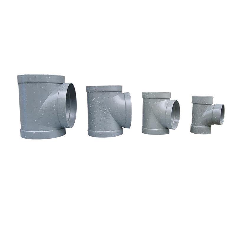
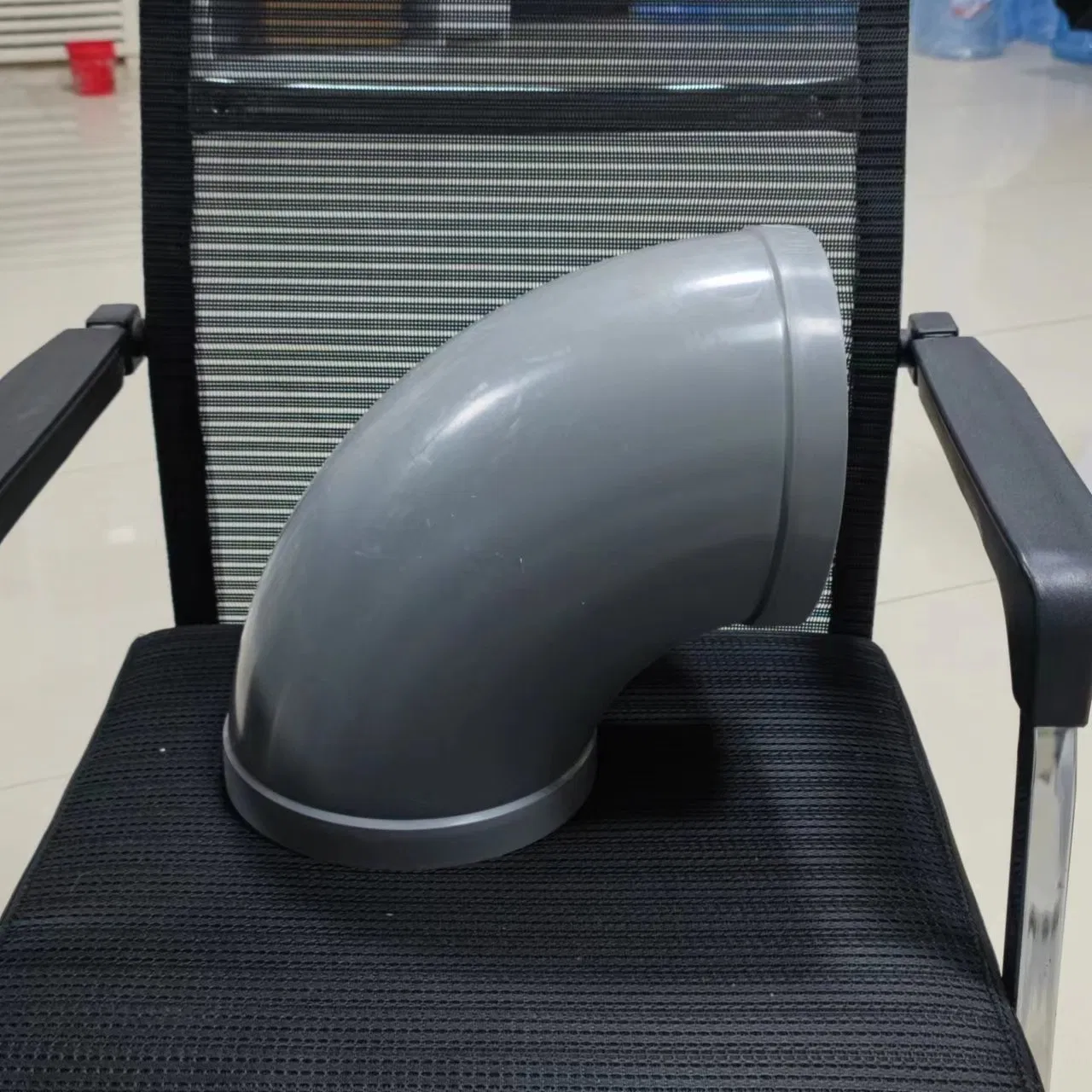
XICHENG’s published product channels confirm PP/PVC ventilation elbows, tees, reducers, flanges and couplings. The documented component range includes PP/PVC ventilation elbows, duct tees, reducers and ventilation flanges; couplings or sleeves remain project-defined unless a current quotation assigns a separate code. Confirmed configurations include round 90-degree elbows, round equal tees with a 90-degree branch, custom round or rectangular reducers, welding flanges and socket-style couplings. Both molded and fabricated or processed construction appear within the family, so the manufacturing method is selected by fitting type and size rather than assumed from the family name.
Connections may be prepared for direct welding, socket or coupling assembly, or a detachable flange interface. Gray and beige or cream products appear in XICHENG listings and images, but color is not a substitute for a resin grade or chemical-compatibility review. Final material, wall construction, dimensions, connection details and inspection scope belong on the approved order documentation.
Do Not Select from Nominal Diameter Alone
A nominal diameter does not fully describe a ventilation fitting. An elbow also needs an angle, radius or centerline geometry and end preparation. A tee needs main-run sizes, branch size, branch angle and orientation. A reducer needs inlet and outlet dimensions, concentric or eccentric alignment, transition length and installation direction. A flange or coupling needs the matching duct outside dimension, joint method and mating interface.
Do not treat these products as generic water-supply or drainage fittings. This page addresses gas and ventilation service, not a liquid-pressure rating. It also does not establish fire resistance, smoke control, certified isolation, a leakage class or an automatic airflow-control function. Those duties require products and documentation selected for that purpose.
Information Required for a Project-Ready Quotation
Provide a fitting schedule or marked drawing with a unique tag for each item. For every tag, list the fitting type, PP or PVC preference, round diameter or rectangular width and height at each end, angle, branch orientation, centerline or transition length, connection method, installation position and quantity. Include the mating duct details so that socket depth, weld allowance, flange face and bolt coordination can be checked.
For laboratory and corrosive exhaust, add the air-stream description: chemicals, expected concentration, normal and upset temperature, humidity, droplets or condensate, particulate or crystallizing deposits, cleaning chemicals and operating schedule. Also provide design airflow and available system information when the fitting geometry must be evaluated for local pressure loss or branch distribution.
The quotation should return the proposed fitting type, material, principal dimensions, manufacturing method, connection details, supplied scope, exclusions, documentation and commercial terms. The approved fabrication drawing and fitting schedule, rather than a marketplace reference value, define the delivered configuration.
Key Specifications and Available Fitting Schedule
Available Product-Family Configuration
The XICHENG family covers the fittings required to turn, branch, reduce and join PP/PVC ventilation ducts. The following schedule is a selection guide. It does not replace a fabrication drawing, because one project may require molded standard components while another uses fabricated transitions or custom interfaces.
| Fitting Type | Primary Function | Order-Defining Information |
|---|---|---|
| PP/PVC ventilation elbow | Changes duct direction while maintaining a continuous exhaust path | End size, angle, centerline or radius, end preparation and available envelope |
| PP/PVC duct tee or branch fitting | Connects a branch to the main exhaust run | Main sizes, branch size, branch angle, orientation and flow direction |
| PP/PVC duct reducer or transition | Connects different duct sizes or shapes | Inlet/outlet dimensions, concentric or eccentric alignment and transition length |
| PP/PVC ventilation flange | Creates a detachable interface to duct, equipment or another material system | Duct size, face geometry, bolt pattern, gasket and mating-flange details |
| Coupling or sleeve | Joins aligned duct sections with a socket or welded connection | Mating outside dimensions, insertion depth, weld method and axial clearance |
Published Examples and Project-Specific Values
XICHENG product records identify separate elbow, tee, reducer and flange families, including PP/PVC elbows, tees, reducers and flanges on their respective product records. Those model references confirm that the components are real XICHENG product lines; they are not combined into one invented SKU on this multi-component page.
Some listings show broad diameter spans or example dimensions. Because these spans differ by component and manufacturing method, this page does not present them as a universal stock range. The applicable size and whether the item is molded, machined or fabricated are confirmed against the requested tag.
Material and Service Fields to Confirm
The order record should state the selected PP or PVC construction and the actual exhaust exposure. The material review includes the fitting body and any weld rod, gasket, fastener or transition component that contacts the air stream. Temperature, moisture and chemical concentration can change the suitability of an otherwise familiar material name.
Documentation and Acceptance Scope
For simple replacement fittings, an approved dimensioned sketch may be sufficient. For a coordinated exhaust package, request a fitting schedule, fabrication drawings, material identification, connection notes and inspection records. Add pressure or leak testing only when the system specification defines a method, test pressure, allowable result and responsible party.
How Each Ventilation Fitting Changes the Duct Route
Elbows Redirect the Exhaust Run
An elbow changes direction between two duct sections. XICHENG product pages confirm round PP elbow configurations, including 90-degree products and welded connection options. The engineering question is not merely whether the elbow turns 90 degrees. Radius, centerline distance, nearby fan or branch location and available ceiling space affect both fit and airflow behavior.
Use a dimensioned route when the elbow must clear beams, cable trays, lighting or service piping. Where a tight turn is unavoidable, include the design airflow and the system engineer’s allowable local loss so the geometry can be reviewed in context.
Tees Create a Main-to-Branch Connection
A tee joins a branch to a main exhaust run. XICHENG listings confirm equal round tees with 90-degree branches and custom sizing. A reducing tee requires three connection sizes, not one: upstream main, downstream main and branch. The drawing should also identify branch orientation because a physically correct tee can still arrive rotated incorrectly for the installed route.
Air does not divide or combine solely according to fitting diameter. Branch resistance, downstream pressure, dampers, hoods and fans determine the operating distribution. The tee provides the physical junction; it does not balance the branches by itself.
Reducers Connect Different Sizes
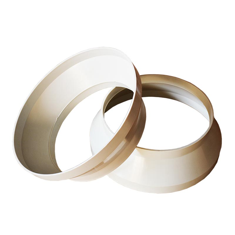
A reducer transitions between different duct dimensions. XICHENG sources confirm custom round and rectangular reducer arrangements. State whether the transition should be concentric, eccentric or offset to a defined datum. That decision matters where the duct must maintain a top elevation, bottom elevation or wall line.
Transition length should be coordinated with space and airflow objectives. A very short reducer may fit the drawing envelope but can introduce a more abrupt velocity change. A longer transition may improve the layout but conflict with access or supports. The approved drawing resolves that tradeoff.
Flanges Provide a Detachable Interface
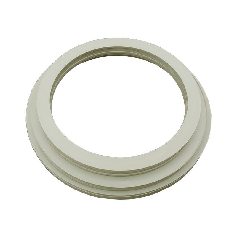
PP flanges allow a duct section to be disconnected from equipment, a scrubber, fan, damper or removable spool. XICHENG publishes welding-flange products for pipe connection. A flange inquiry should include the mating face and bolt information; nominal duct size alone does not confirm that two flange systems will align.
Gasket material, fasteners and tightening procedure are part of the joint. They must be selected for the exposure and mechanical load. The plastic flange should not be forced into alignment by uneven bolt loading or used to carry unsupported duct weight.
Couplings Join Straight Duct Sections
A coupling or sleeve joins aligned duct sections and can provide a socket-style assembly before welding. XICHENG-attributed Environmental Expert information confirms PP coupling configurations and hot-air-welded installation context. Because that listing belongs to a different regional XICHENG entity, its sizes are supporting evidence rather than a universal Shenzhen catalog range.
The coupling must match the actual duct outside dimension and insertion arrangement. Allow for field access to complete and inspect the joint; a coupling placed directly against a wall or structural member may be impossible to weld correctly.
Custom Branches and Transitions Complete Non-Standard Routes
Laboratory exhaust layouts often need offsets, unequal branches, round-to-rectangular transitions or equipment adapters that are not represented by a simple catalog symbol. XICHENG’s product channels repeatedly confirm customization. These items should be ordered from an approved fabrication drawing with clear datums and connection callouts.
A custom fitting is still part of the airflow system. The drawing should show flow direction, internal intersections and any abrupt changes that require review. Fabrication feasibility, installation access and system pressure-loss impact should be checked together rather than sequentially after manufacture.
PP and PVC Material Options
PP for Laboratory and Process-Exhaust Fittings
Polypropylene is directly represented across XICHENG’s elbow, tee, reducer, flange and coupling records. It is commonly considered for laboratory and process-exhaust systems because plastic fabrication allows the fitting package to be coordinated with PP duct and equipment. That family-level suitability does not mean PP is compatible with every chemical mixture or temperature.
Review the complete exposure, including normal operation, cleaning, startup, upset conditions and possible condensate. A gas stream that appears mild when dry may create a different exposure after cooling or condensing at an elbow or reducer.
PVC for Selected Ventilation Fitting Configurations
PVC appears in XICHENG’s PP/PVC ventilation-accessory listings and selected tee and reducer pages. It may be considered when the specified duct material, chemical environment and temperature permit it. The buyer should state the required PVC type or project specification rather than relying on the material name alone.
Where PP and PVC sections meet, the transition method must be engineered. Directly treating unlike plastics as interchangeable welding materials can create an unsuitable joint. A flange or purpose-designed adapter may be required depending on the system.
Component-Level Compatibility Review
A fitting is more than its visible body. A complete review can include weld rod, gasket, flange hardware, reinforcement, inserts and any sensor or damper connection near the fitting. Only components exposed to the gas stream need the same type of chemical review, but external components still require consideration for ambient corrosion and mechanical loading.
| Review Field | Information from Buyer | Decision Recorded in Quotation or Drawing |
|---|---|---|
| Air-stream chemistry | Chemicals, concentration and possible mixtures | Selected body and exposed-component materials |
| Temperature | Normal, startup, cleaning and upset values | Applicable material/configuration and stated limit |
| Moisture | Humidity, droplets, condensate and drain requirement | Orientation, low-point treatment and joint details |
| Deposits | Dust, salt, crystals, sticky material or reaction products | Geometry, cleanout access and maintenance approach |
| Cleaning | Cleaning chemicals, frequency and method | Material and access provisions compatible with maintenance |
Color Is Not a Material Specification
XICHENG images show gray and beige or cream fittings. Those colors help identify pictured products but do not prove resin grade, flame-retardant formulation, recycled content, temperature capability or chemical resistance. Procurement documents should identify the required material and any supporting documentation separately from color.
Custom Sizes, Shapes and Connection Methods
Record Every Connection Dimension
For a straight coupling, one nominal size may be enough only when both mating ducts are genuinely identical and the outside dimensions are known. Most fittings need more information. A reducer has at least two end sizes; a tee has three; an offset transition also needs the positional relationship between its inlet and outlet.
Use actual units and avoid ambiguous shorthand. For round fittings, state the duct outside diameter and whether the connection slips over, slips inside or meets the duct edge-to-edge. For rectangular fittings, state width by height and identify which dimension is horizontal in the installed orientation.
Round and Rectangular Geometry
Round elbows, tees, reducers, flanges and couplings are confirmed in XICHENG’s published family. Selected reducers are also described as round or rectangular, supporting custom transitions for non-round duct routes. A round-to-rectangular fitting should identify both shapes, their datums and the available transition length.
Rectangular fittings may require reinforcement or a different fabrication approach as dimensions increase. The final construction should be returned on a drawing rather than inferred from a photograph of a smaller round component.
Direct Welded Connections
Welding is explicitly listed for XICHENG elbows, tees and flanges. In a direct welded joint, the fitting and duct ends must be dimensionally compatible and accessible to the installer. The weld method, preparation and acceptance should follow the material and project specification.
A welded connection creates a permanent joint. It can be appropriate for long duct runs but may be inconvenient at equipment that requires periodic removal. Use detachable interfaces at fans, scrubbers, dampers or service spools when maintenance access justifies them.
Socket and Coupling Connections
A socket or coupling can align two duct ends and provide a controlled joining zone. The order should define mating outside dimensions, socket depth and whether the assembly is supplied loose, factory fitted or field welded. Axial installation clearance must be considered; a coupling cannot be inserted after two fixed duct sections have been installed without sufficient movement.
Flanged and Equipment Interfaces
A flange creates a removable connection but introduces more coordination fields: face diameter or width and height, bolt-circle or hole pattern, hole size, flange thickness, gasket type and mating material. Provide the equipment vendor’s connection drawing whenever the fitting meets a fan, scrubber, fume hood collar or imported component.
Do not assume that two items labeled with the same nominal diameter share a bolt pattern. The approved interface drawing should show both sides of the connection and identify which party supplies gaskets, fasteners and any adapter.
Airflow, Pressure Loss and Layout Effects
Every Direction Change Adds Local Resistance
An elbow redirects moving air, so it contributes local resistance in addition to the friction of straight duct. The amount depends on geometry, airflow, duct size and nearby flow conditions. This page does not publish one pressure-drop value for all XICHENG elbows because no family-wide tested coefficient has been verified.
For system calculations, use the fitting geometry accepted for the project and the engineer’s selected calculation method. If the system has little available static pressure, disclose that constraint before the elbow radius or route is finalized.
Branch Fittings Affect Flow Distribution
A tee combines or divides air streams. The resulting branch airflow depends on system resistance, fan operation, terminals and control devices, not simply on cross-sectional area. A tee should therefore be coordinated with balancing dampers or airflow-control products where branch quantities must be set or maintained.
Provide the intended flow direction and design airflow for each leg. A geometry selected for dividing flow may not behave identically when used to combine two exhaust branches. The fitting schedule and system schematic should agree.
Reducers Change Velocity and Static-Pressure Conditions
When duct area decreases, velocity generally increases for the same volumetric flow; when area increases, velocity generally decreases. The transition geometry influences turbulence, separation and local loss. Concentric, eccentric and offset reducers can also affect drainage and available space differently.
The transition should not be selected from large-end and small-end dimensions alone when the pressure budget is important. Include the design airflow, available length and alignment constraint so the final geometry can be evaluated as part of the duct model.
Fittings Do Not Replace Airflow Control
Elbows, tees, reducers, flanges and couplings establish the physical path. They do not measure airflow, maintain constant airflow, modulate to a command, prevent reverse flow or isolate the system. Use a suitable manual damper for fixed balancing, a motorized damper for commanded positioning, a backdraft damper for passive reverse-flow response, or a CAV/VAV product when measured airflow control is required.
Related components can be reviewed under Laboratory Ventilation Components. The fitting layout and control strategy should be coordinated so that a damper, sensor or controller is not placed where disturbed flow compromises its required installation conditions.
Laboratory and Corrosive Exhaust Applications
Laboratory General Exhaust Networks
PP/PVC ventilation duct fittings can complete laboratory general-exhaust routes where the selected plastic is appropriate for the expected air stream. Elbows navigate building structure, tees connect branch runs, reducers coordinate velocity or equipment connections, and flanges create removable interfaces.
Fume Hood and Local Exhaust Branches
Fume hood exhaust often combines several branches into a header. Each branch connection should be shown on the duct schematic with its design airflow, damper location and service access. The fittings create the route, while the hood, fan and control system establish and manage containment airflow.
Browse the related Laboratory Fume Hoods category when the project scope includes the source-capture equipment as well as the ductwork.
Chemical Process and Scrubber Connections
Plastic fittings are also used between process pickups, exhaust headers, fans and treatment equipment. At a scrubber or fan, flanges and custom transitions are often more important than a catalog elbow because equipment nozzles, maintenance clearances and vibration interfaces must be coordinated.
Provide the treatment-equipment connection drawing and gas conditions. Chemical exposure can change after mixing branches or passing through a process, so material selection should follow the actual location of each fitting rather than one description for the whole plant.
Applications Requiring Another Product or Review
Do not use this family as fire dampers, smoke dampers, certified shutoff devices, liquid-pressure plumbing fittings or structural supports. It is also not a substitute for a flexible connector where vibration isolation is required, or for a drain component where condensate collection is the primary duty.
For an airflow-balancing device, review the PP/PVC Round air volume control damper. For automatic positioning, review the PP/PVC Motorized air volume control damper. For passive reverse-flow response, review the PP/PVC Backdraft damper.
Duct Fitting Selection and Drawing Coordination
Start with the Airflow Schematic
Mark each source, branch, header, fan and treatment device on one airflow schematic. Add the design airflow and direction at every fitting. This identifies whether a tee combines or divides flow and whether a reducer is an expansion or contraction in the operating direction.
Show dampers, sensors and access points on the same schematic. This prevents a fitting from being approved in a location that leaves too little straight duct for the adjacent device or blocks the technician’s working area.
Create a Tag-by-Tag Fitting Schedule
Assign a tag to every elbow, tee, reducer, flange and coupling. The schedule should state material, end dimensions, angle or branch geometry, connection, quantity and drawing reference. Tags prevent two visually similar fittings with different orientations from being mixed during fabrication or installation.
Keep one row per physical fitting even when several rows share the same nominal size. Unique tags provide traceability for drawing comments, packing, site distribution and inspection results.
Coordinate Geometry with the Building
Check ceiling height, structure, access panels, services and equipment-removal paths before approving fitting dimensions. Elbow centerlines, reducer lengths and tee orientations must fit the real installation envelope. Use fixed datums rather than dimensions taken from an unverified architectural image.
Where the route is congested, supply a coordinated section or three-dimensional view. A plan view may not reveal that an elbow conflicts vertically with a beam or that a flange cannot be separated for maintenance.
Review Material at Each System Location
Map chemicals and temperatures along the route. Exhaust streams may mix at tees, cool through long runs or collect condensate at low points. The required material and drainage detail can therefore change between the source branch and the treatment-equipment connection.
Record the reason for each material transition. If one branch introduces a new chemical, its downstream tee and header should be reviewed for the combined exposure rather than the original upstream condition.
Close the Drawing Approval Loop
Before manufacture, verify every connection against the mating duct or equipment drawing. Resolve units, orientation, socket direction, flange pattern, weld allowance and supplied scope. Approval should identify the drawing revision; comments in separate email threads should be incorporated into the controlled document.
When field dimensions remain open, label them as hold points instead of estimating them. The project can then release unaffected fittings while reserving the unresolved adapter or transition for verified site measurements.
Installation, Inspection and Maintenance
Store and Handle without Distortion
Keep fittings supported during storage and transport. Do not load large flanges, branches or fabricated transitions through one edge. Before installation, inspect for shipping damage, deformation and contamination that could affect alignment or welding.
Retain identification labels until the fitting is installed and checked. Protect prepared ends from impact and keep joint surfaces clean rather than using them as temporary supports on site.
Verify Tags, Orientation and Flow Direction
Match the fitting tag to the latest drawing before lifting it into place. Confirm branch rotation, eccentric-reducer datum and flange face direction. An incorrectly rotated tee or reducer can appear dimensionally correct until the next duct section is installed.
Dry-fit the connected route where practical. Check that branch centerlines and equipment nozzles align without pulling the plastic into position.
Support the Duct, Not the Fitting Joint
Provide duct supports so that elbows, tees, couplings and equipment flanges do not carry unintended pipe weight or alignment force. Add support near heavy transitions and removable equipment interfaces while preserving access to welds, bolts and inspection points.
Support spacing and hardware are project engineering decisions. They depend on duct dimensions, orientation, temperature, external loads and building conditions, so no one spacing value should be copied across installations.
Complete and Inspect Each Connection
Prepare welded or socket joints using the approved material procedure and accessible working clearance. For flanges, align faces without forcing them together and tighten fasteners evenly according to the project method. Record visual or dimensional checks and any specified leak test against the fitting tag.
Where a test is required, agree on boundaries before closing ceilings or insulation. Record the method and result rather than reporting only that the duct passed.
Plan Access for Cleaning and Future Changes
Inspect fittings where deposits, condensate or process carryover are likely to collect, especially elbows, branches and low points. If the service requires periodic removal, use an accessible flange or spool arrangement. Maintenance methods must remain compatible with the selected plastic and joint materials.
Update the as-built fitting schedule after site changes. A documented replacement geometry is easier to reproduce than a component that must be measured again after failure or shutdown.
Custom Manufacturing and Quotation Deliverables
Drawing-Based Manufacturing
XICHENG sources show both molded and custom processed ventilation fittings. The proposed method depends on fitting type, dimensions, quantity and geometry. Custom fabrication can address unusual transitions and equipment interfaces, while a molded component may suit an established round configuration.
Minimum RFQ Dataset
Submit enough information to remove guesswork from every connection. A complete package reduces drawing revisions and makes competing quotations easier to compare.
| RFQ Section | Required Buyer Input | Expected XICHENG Return |
|---|---|---|
| Fitting identity | Tag, type, quantity and location | Itemized fitting schedule and supplied scope |
| Geometry | All end sizes, angles, orientation, centerlines and datums | Dimensioned fabrication or approval drawing |
| Connections | Weld, socket, coupling or flange plus mating details | End preparation, allowances and interface notes |
| Service | Airflow, chemistry, temperature, moisture and deposits | Proposed material/configuration and unresolved limits |
| Project | Quantity, destination, schedule and documentation needs | Lead time, packing, commercial terms and document list |
What the Quotation Should Not Hide
The return should identify assumptions, exclusions and fields still requiring approval. If pressure loss, leakage testing, material certificates or special inspection are required, they should appear as explicit deliverables rather than being inferred from general product language.
Configuration Approval Defines the Product
These products are non-standard and customizable. The final fitting is defined by the accepted tag schedule, drawing revision, material, connection details and commercial scope. Family-page examples help select the product type; they do not override project-approved documentation.
Related Laboratory Ventilation Products
Ventilation Ducts
Fittings must match the duct material, outside dimensions and joining method. Browse the full Products catalog while the dedicated PP/PVC ventilation-duct page is being completed.
Manual Balancing Dampers
Use the PP/PVC Round air volume control damper when a branch needs a fixed balancing position rather than only a physical fitting.
Motorized and Backdraft dampers
Use the motorized damper for commanded blade positioning and the backdraft damper for passive reverse-flow response. Confirm straight-run and access requirements before locating either next to an elbow or tee.
Engineering Inquiry
For a coordinated package of fittings, duct and airflow-control components, submit the schematic and fitting schedule through the contact page.
Frequently Asked Questions
Which ventilation duct fittings are included?
The XICHENG family includes elbows, tees, reducers, flanges and couplings. Custom branches, offsets and round-to-rectangular transitions can be reviewed from drawings. Each item is quoted against its own tag and connection data.
Are both PP and PVC available?
PP is confirmed across the published fitting family, and PVC appears in selected XICHENG PP/PVC listings. Final availability and suitability depend on fitting type, size, chemistry and temperature. State the project resin specification when one has already been selected.
What sizes can XICHENG manufacture?
XICHENG listings confirm custom sizing, but published ranges vary by fitting and process. Provide every connection dimension; the quotation will identify the applicable manufactured configuration and whether it is molded or fabricated.
Can round and rectangular ducts be connected?
Selected reducers are described as round or rectangular, so a custom transition can be evaluated. The drawing must define both end shapes, dimensions, datums and transition length, plus the orientation of the rectangular end.
Are the fittings welded or socket connected?
Welded, socket or coupling and flanged arrangements appear within the family. The selected method depends on the fitting, mating duct, maintenance needs and project specification. Detachable flanges are usually considered where equipment must be removed.
Do the fittings have a published pressure-drop value?
No single value applies to every elbow, tee or reducer. Pressure loss depends on airflow, size, radius, branch relationship, transition geometry and surrounding duct conditions. Use the approved geometry in the system calculation.
Can these fittings be used for every corrosive gas?
No. Provide chemical identity, concentration, temperature, moisture, deposits and cleaning method. Compatibility must be reviewed for the selected body and exposed joint components, including gaskets and weld materials where applicable.
Are these plumbing pressure fittings?
No. This page covers gas and ventilation duct service. Liquid-pressure duty requires a separately specified piping product, pressure class and joining standard. A similar appearance does not establish equivalent service.
What should be checked before approving a tee?
Confirm all three connection sizes, main and branch flow directions, branch angle, rotation, centerline dimensions, connection method and access for joining and support. Also check whether the tee is used to combine or divide airflow.
What information produces the fastest accurate quotation?
Send a tagged fitting schedule, dimensioned duct layout, airflow schematic, material preference, air-stream data, connection details, quantities, destination and required documentation. Identify unresolved site dimensions instead of replacing them with estimates.
Contact the Xicheng Engineering Team Today
Send your duct layout, fitting schedule, inlet and outlet dimensions, branch orientations, material preference and exhaust-gas conditions. XICHENG will review the requested elbows, tees, reducers, flanges and couplings and return a coordinated configuration, drawing requirements and quotation within 24 hours.
Shenzhen Office: No. 34 Zhenxing Road (Shengtaian Heavy Industrial Park B), Loucun, Guangming New Dist, Shenzhen, Guangdong, China
WhatsApp: +86 181 2647 8161
Engineering Mailbox: fanalax34@gmail.com