


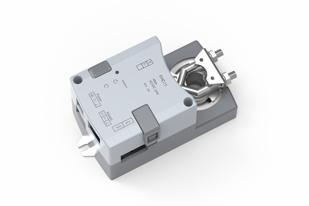
Description
This fume hood face velocity controller closes the laboratory exhaust-control loop around the measured velocity at the hood opening. A face-velocity sensor supplies the feedback signal, and the integrated rotary actuator repositions a compatible butterfly damper to correct the measured condition. It is the direct-feedback option within XICHENG’s laboratory airflow controls and actuators range, distinct from sash-position-based demand control.
- Direct face-velocity feedback rather than sash-position demand
- Integrated 3-second, 4 N·m rotary actuator for a compatible butterfly damper
- One analog face-velocity input, one personnel-detection input, and two configurable outputs
- 24 VAC/DC power, RJ12 panel connection, and RS-485 Modbus RTU communication
- Low-velocity audible/visual alarm and energy-saving operating logic
The controller is configured to order. Before selection, match it to the face-velocity sensor and scaling, butterfly damper mechanics, available exhaust pressure, fan or VFD response, hood geometry, alarm limits, field wiring, and commissioning method. The controller regulates the selected damper; it does not replace the rest of the fume hood exhaust system.
Is This Face Velocity Controller the Right Fit?
Choose This Controller When
Choose this fume hood face velocity controller when the hood design uses a sensor to measure face velocity and a fast integrated actuator to modulate a butterfly damper. It is intended for control loops that react to the measured hood condition rather than calculate exhaust demand only from sash position or accept a generic command from another controller.
- The fume hood exhaust branch uses a compatible rotary butterfly damper and the required operating torque is within the confirmed actuator capability.
- The control design provides a 0-10 VDC or 2-10 VDC face-velocity sensor signal and defines its measurement range, scaling, location, and failure response.
- The system needs a 24 VAC/DC integrated controller-actuator, low-velocity alarm logic, local panel connectivity, and RS-485 Modbus RTU communication.
- The commissioning plan will measure actual hood face velocity and verify alarm, damper movement, exhaust response, and BMS points under the required operating states.
When This Controller Is Not the Right Choice
A face velocity controller cannot make an undersized exhaust system perform correctly. It cannot create fan capacity, recover unavailable static pressure, correct poor hood aerodynamics, or prove containment from actuator position. It is also not an automatic sash controller, a room differential-pressure controller, a general VAV terminal controller, or a Venturi air-valve control package. Check that the hood, duct, fan or VFD, butterfly damper, sensor, and balancing strategy can produce the required airflow response.
Choose a different controller architecture when sash-position input is the primary demand signal, when the controller must drive a separately mounted external actuator, or when automatic sash movement and anti-pinch safety are the main control tasks.
Information Needed For An Accurate Quotation
For each hood tag, provide the hood type and opening dimensions, sash arrangement, target face velocity, operating and alarm states, face-velocity sensor type and signal scaling, butterfly damper size and shaft interface, available pressure, normal and emergency airflow, actuator direction, 24 V power source, output assignments, local panel requirement, Modbus network data, alarm and fail sequence, quantity, destination, and available drawings. XICHENG will use this information to propose the controller configuration, included components, wiring and communication interfaces, items requiring confirmation, and commercial pricing.
Key Specifications
Controller, I/O And Environmental Data
These specifications cover the FHC11 controller and integrated actuator. Use them to check electrical and mechanical compatibility before selecting the sensor, damper, panel, and BMS connection. Face-velocity setpoint, alarm threshold, output assignments, Modbus point list, and supplied accessories are configured for each project.
| Item | Specification | Selection Requirement |
|---|---|---|
| Product type | Fume hood face velocity controller with integrated rotary actuator | Use where direct face-velocity feedback controls exhaust airflow |
| Model / SKU | FHC11 | Use this model reference in product schedules and orders |
| Primary application | Variable-air-volume control for butterfly-damper fume hood exhaust | Confirm hood, exhaust branch, damper and fan arrangement |
| Supply power | 24 VAC or 24 VDC, ±10% | Confirm source, isolation, protection and grounding |
| Actuator | Integrated 3S4N fast actuator; 3 s operating time and 4 N·m torque | Confirm shaft, required torque, travel direction and damper load |
| Analog input | 1 input; 0-10 VDC or 2-10 VDC for a face-velocity sensor | Confirm sensor output, range, scaling and signal-loss behavior |
| Digital input | 1 input for personnel detection | Confirm sensor type, contact logic and energy-saving sequence |
| Digital / relay outputs | 2 configurable outputs | Confirm assignments such as fan/closed-valve linkage and hood lighting |
| Local panel interface | Independent RJ12 communication port | Confirm compatible panel, cable and supplied scope |
| BMS communication | RS-485 with Modbus RTU support | Confirm address, baud rate, parity, register map and point ownership |
| Operating functions | Low-velocity audible/visual alarm and energy-saving mode | Define thresholds, delays, reset, override and failure behavior |
| Operating environment | 0 to +50 °C; 10-95% RH, non-condensing | Confirm installation location remains within limits |
| Storage environment | -20 to +50 °C; 10-95% RH, non-condensing | Confirm transport and storage conditions |
Controller Dimensions And Mounting Clearance
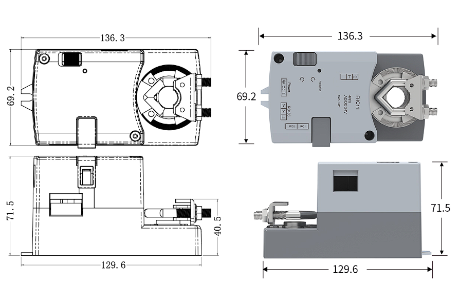
The drawing below shows the controller and actuator from multiple directions. Use the indicated orientation when checking mounting clearance, shaft position, wiring access, and service access.
| Dimension | Value | Installation Use |
|---|---|---|
| Top-view overall length | 136.3 mm | Check horizontal installation clearance |
| Top-view body width | 69.2 mm | Check adjacent duct and enclosure clearance |
| Side-view base length | 129.6 mm | Coordinate mounting footprint |
| Side-view overall height | 71.5 mm | Check access above the damper shaft |
| Lower/shaft-center dimension | 40.5 mm | Read with the side view; this is not a separate overall dimension |
How To Read The Power Ratings
The controller carries two power references. Its product label shows 9 VA with AC supply and 5 W with DC supply, while the electrical specification lists maximum values of 20 VA AC and 10 W DC. Use the maximum values when sizing the upstream power source unless the wiring sheet supplied with the selected configuration states a different design load. The label values identify the delivered unit and should not be combined with the maximum ratings as one consumption figure.
Face Velocity Control Strategy
How The Closed Loop Works
The face-velocity sensor measures air movement at the hood and sends a 0-10 VDC or 2-10 VDC signal to the controller. The controller interprets the scaled signal, compares it with the configured face-velocity setpoint, and drives its integrated actuator. The actuator rotates the connected butterfly damper, changing exhaust airflow until the measured signal returns to the intended control range. This input-measure-adjust cycle distinguishes a direct face-velocity controller from a position-only actuator or a sash-position demand controller.
The measured result depends on more than the controller. Sensor location must represent the hood condition specified by the designer; scaling must match the sensor range; the damper must have usable authority over the required airflow states; and the fan or VFD must respond without exhausting the available pressure margin. A stable control loop also requires suitable tuning, signal filtering, alarm delays, and mechanical movement without excessive backlash or binding.
What The Controller Can And Cannot Correct
The controller can react to a valid face-velocity signal and move a compatible damper. It can therefore compensate for changes that remain within the controllable range of the exhaust system, such as a change in hood opening or a configured operating-mode transition. It cannot compensate indefinitely for insufficient fan capacity, a blocked duct, a damper that is too small or already fully open, unstable building pressure, a poorly placed sensor, incorrect signal scaling, or hood geometry that does not deliver the required containment behavior.
For this reason, actuator position is diagnostic information, not proof of face velocity. A damper at 60% open can correspond to different airflows as duct pressure and system resistance change. Commissioning must compare the actual measured hood result with the required operating and alarm states, then document the sensor signal, damper position, fan response, and BMS indication at those conditions.
Alarm And Energy-Saving Logic
When measured face velocity falls below the configured threshold, the controller can initiate audible and visual alarm behavior through the connected control panel and outputs. Set the threshold, delay, latching or automatic reset, acknowledgement, BMS indication, and sensor-failure response to match the hood operating sequence. The alarm identifies an abnormal condition; it does not correct the exhaust-system cause.
Energy-saving mode can reduce airflow demand when the personnel-detection input and hood operating sequence allow it. Configure the occupied and unoccupied states, minimum permitted exhaust, return-to-normal behavior, time delays, manual override, and alarm interaction before commissioning. The resulting energy reduction depends on the complete ventilation system and operating schedule, so it is not a fixed percentage attributed to the controller alone.
Integrated Actuator And Damper Interface
Fast Rotary Actuation
The integrated 3S4N actuator has a 3-second operating time and 4 N·m torque. It translates controller output into fast rotary movement at the connected butterfly-damper shaft. The integrated arrangement removes a separate controller-to-actuator selection step, but the shaft geometry, required torque, direction, usable angle, mounting orientation, mechanical stops, and service clearance still need to match.
Fast travel is valuable only when the rest of the airflow loop can respond in a controlled manner. A rapidly moving blade can still produce overshoot or hunting if the face-velocity signal is noisy, the damper is oversized, the fan response is slow, or the control tuning is unsuitable. The commissioning sequence should therefore verify actual system response rather than assume that the actuator’s rated operating time equals the complete hood-control response.
Butterfly damper Compatibility
This controller is designed for fume hood systems using a butterfly damper or butterfly valve. Mechanical compatibility depends on the shaft and mounting arrangement, while airflow compatibility depends on damper size, blade characteristic, pressure condition, required minimum and maximum airflow, and available system pressure. The controller and actuator move the damper, but the damper body and exhaust system determine how that movement changes airflow.
Before ordering or installation, check the shaft dimensions and shape, opening direction, actuator mounting plane, 4 N·m torque margin at the operating pressure, damper rotation limits, wiring access, and any required bracket, coupler, or adapter. For chemical exhaust, review the damper body, blade, shaft, seals, exposed hardware, and sensor tubing against the actual air stream. Locating the controller enclosure outside the duct does not establish chemical compatibility for the complete assembly.
Product And System Boundary
The product combines the face-velocity control function and rotary actuator. Unless the quotation states otherwise, the face-velocity sensor, butterfly damper body, local display panel, personnel sensor, fan or VFD, power supply, control enclosure, field wiring, network cabling, BMS programming, balancing, containment testing, and commissioning are separate items. Confirm which components are included by XICHENG, selected as options, or supplied by other contractors.
The controller also does not replace a fire damper, smoke damper, certified isolation device, room-pressure controller, or automatic sash safety system. Where one project requires several of these functions, the controls designer must define how the independent devices interact during normal operation, emergency exhaust, fire or smoke mode, power loss, communication loss, and restart.
I/O, Wiring And BMS Integration
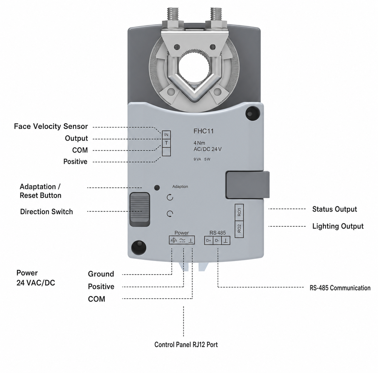
The connection reference below identifies the face-velocity sensor input, adaptation/reset control, direction switch, power terminals, two output channels, RS-485 interface, and local panel port. Use it for initial interface planning, then wire the selected configuration according to its supplied diagram and electrical ratings.
| Interface | Function | Selection And Wiring Check |
|---|---|---|
| IN / T sensor terminals | Face-velocity sensor output, common and positive connection | Confirm 0-10 VDC or 2-10 VDC range, polarity and scaling |
| Adaptation / reset control | Controller and actuator setup function | Use during setup and commissioning |
| Direction switch | Sets the required actuator movement direction | Verify damper opening direction before closed-loop testing |
| 24 VAC/DC power | Ground, positive and common terminals | Confirm source capacity, protection, grounding and polarity |
| RO1 / RO2 outputs | Status and lighting functions shown in the reference arrangement | Confirm final assignment, contact logic and electrical rating |
| RS-485 D+ / D- | Modbus RTU BMS communication | Confirm polarity, topology, termination and communication settings |
| Control-panel RJ12 port | Connection to the compatible local panel | Confirm panel model, cable and supplied scope |
Sensor And Personnel-Detection Inputs
The analog input accepts a 0-10 VDC or 2-10 VDC face-velocity sensor signal. Specify the signal convention, zero and span values, engineering units, valid operating range, cable and shield requirements, and response outside the valid signal range. During commissioning, compare the controller reading with the selected reference instrument and record any calibration or scaling adjustment.
A separate digital input is available for personnel detection. This input can participate in the energy-saving sequence, but the reduced-flow state still needs a defined control logic. Set the sensor contact state, occupancy delay, unoccupied airflow, minimum exhaust limit, return-to-normal response, override, and alarm interaction. If personnel detection is not used, show the unused input condition on the wiring plan.
Relay Outputs And Local Panel Connection
RO1 and RO2 can be assigned to functions such as fan or closed-valve status linkage and fume hood lighting control. Before wiring, define the purpose of each output, contact logic, electrical rating, normal and alarm state, and any interposing relay. Do not connect a motor, lamp, or other load directly until the output rating and interface have been confirmed.
An independent RJ12 port supports connection to the compatible local control panel. Confirm the panel model, cable type and length, connector orientation, power and communication arrangement, displayed values, alarm acknowledgement, operator permissions, and supplied scope. An RJ12 connector is a physical interface; it does not establish compatibility with an unrelated panel that uses the same connector shape.
RS-485 Modbus RTU Integration
The BMS interface supports RS-485 communication with Modbus RTU. Before integration, agree the device address, baud rate, parity, stop bits, register map, data type, scaling, read/write permissions, polling interval, alarm points, command ownership, and communication-loss behavior. The controls contractor should also coordinate cable topology, termination, biasing, shielding, grounding, and separation from power wiring.
Point-to-point testing should verify that face velocity, operating state, alarm status, commands, and available feedback are interpreted correctly at both the controller and BMS. Modbus communication does not define the operating sequence by itself. Specify which commands can come from the BMS, which local functions retain priority, and how the controller responds when network communication is lost.
Applications And Project Fit
Variable-Air-Volume Fume Hood Exhaust
The primary application is a laboratory fume hood whose butterfly-damper exhaust branch varies airflow in response to measured face velocity. It can be used in new installations and controlled retrofits when the sensor arrangement, airflow states, damper mechanics, fan response, alarm sequence, BMS interface, and field test method are defined. Direct measurement allows the controller to react to the hood’s actual velocity signal rather than rely only on a sash-position calculation.
Hood width, sash configuration, opening area, bypass design, duct connection, internal obstructions, room air distribution, and exhaust-system behavior can all change the relationship between damper position and face velocity. Size, configure, and commission the controller for each hood type rather than copying one set of control values across dissimilar hoods.
New Installations And Retrofits
For a new installation, coordinate the controller with the hood manufacturer, exhaust designer, damper supplier, controls contractor, and commissioning provider before ordering. The hood schedule should identify target velocity and airflow states; the valve schedule should identify size, shaft, torque, pressure and material; and the point list should identify every sensor, input, output, panel and BMS function.
For a retrofit, first record the existing hood opening, current face velocity, damper and shaft condition, available actuator clearance, fan or VFD response, sensor location, wiring, panel, alarms, and BMS points. Reusing existing hardware can reduce site work, but matching voltage or connector shape does not prove compatibility. The retrofit review should also identify whether poor performance is caused by controls or by inadequate exhaust capacity, duct restriction, unstable room pressure, or hood condition.
When Another Controller Should Be Evaluated
Use the Fume Hood Controller with Integrated VAV Actuator when the system needs the broader FHC10 input and actuator options. Choose the Sash-Position Fume Hood Controller when resistive sash-position input defines exhaust demand, the Split-Type Fume Hood VAV Controller when a separate controller must drive an external actuator, and the Automatic Sash Fume Hood Controller when automatic sash movement and VAV airflow control must be integrated.
These related controllers should be compared by primary input, integrated or split architecture, actuator movement, controlled airflow device, I/O, sash-control scope, and supplied components. They are not interchangeable variants distinguished only by model number.
Selection, Installation And Commissioning
Select From The Control Objective
Begin with the required hood behavior, not the controller model. Define the target face velocity, normal and reduced-flow states, emergency response, low-velocity threshold, allowable delays, personnel-detection sequence, local operator actions, and BMS ownership. Then select the face-velocity sensor range and location, butterfly damper size and characteristic, actuator direction and torque, fan or VFD response, and electrical interfaces that can deliver that sequence.
This controller fits systems built around direct analog face-velocity feedback and an integrated fast rotary actuator driving a compatible butterfly damper. If the design instead starts from sash position, an external actuator, a Venturi mechanism, automatic sash movement, or room pressure, choose a controller designed for that task.
Mechanical And Electrical Checks
Before mounting, verify the damper shaft dimensions and condition, required torque, available rotation, opening direction, mechanical stops, bracket or coupler, actuator orientation, nearby ductwork, and access to buttons, terminals, and cables. The actuator must move through the intended range without forcing the damper beyond its limits or transferring misalignment into the shaft.
Before wiring, verify the 24 VAC/DC source, capacity, isolation, overcurrent protection, grounding, and polarity where applicable. Match the face-velocity sensor signal to the selected 0-10 VDC or 2-10 VDC input convention. Confirm personnel input logic, both output assignments and ratings, local panel connection, RS-485 polarity and network settings, cable shielding, and separation from power conductors. Follow the wiring diagram supplied with the selected unit rather than relying only on the interface image on this page.
Commission The Measured Result
Commissioning should start with mechanical travel and wiring checks, then confirm sensor zero/span, signal scaling, actuator direction, damper end positions, normal operating response, and stable closed-loop control. Test the hood at the required sash openings and operating modes while measuring actual face velocity with the specified test method. Record sensor signal, controller indication, damper movement, airflow or fan response, and any adjustment made.
Next verify low-velocity alarm threshold and delay, alarm acknowledgement and reset, personnel-based energy-saving transitions, output interlocks, local panel functions, Modbus points, communication-loss behavior, power-loss behavior, and restart. If the measured result is unstable or below target, diagnose sensor placement, damper authority, fan capacity, duct pressure, tuning and room-air effects before changing alarm thresholds. The completed record should identify the accepted settings and responsibility for future recalibration.
Configuration And RFQ Information
What To Send For Each Hood Tag
This controller is supplied against project requirements rather than as an unconditional one-size configuration. Send one schedule line for each hood tag, including the hood manufacturer and type, opening dimensions, sash arrangement, target face velocity, minimum/normal/maximum/emergency airflow, available exhaust pressure, fan or VFD arrangement, butterfly damper size and shaft details, installation orientation, and available mounting clearance.
The controls portion should identify the face-velocity sensor model, 0-10 VDC or 2-10 VDC range and scaling, personnel input, required alarm threshold and delay, energy-saving sequence, two output assignments, compatible local panel, 24 V power, RS-485 network settings, Modbus point list, failure states, quantity, destination, and documentation language. Include the hood schedule, duct and damper drawing, control schematic, wiring diagram, point list, and sequence of operation when available.
What You Receive In The Technical Proposal
XICHENG’s technical proposal identifies the selected fume hood face velocity controller configuration, actuator data, mechanical interface, applicable electrical and environmental specifications, sensor and panel scope, output assignments, communication scope, supplied and excluded components, items requiring final confirmation, field checks, and commercial pricing. The final technical schedule also shows which ratings apply to each hood tag and which results depend on the connected sensor, damper, fan, field wiring, or commissioning.
Recheck the controller selection if the hood opening, sensor, butterfly damper, shaft, actuator mounting, airflow schedule, power, output use, panel, BMS point list, or control sequence changes. A mechanically similar replacement may still use a different control architecture or electrical interface.
Related Products
The integrated controller must be paired with an airflow-control device and exhaust system that can produce the required hood response. Review the VAV Butterfly damper when selecting the damper body, material, size, shaft, airflow range and pressure condition. The damper is not automatically included with the controller unless the quotation identifies a combined assembly.
For other fume hood control architectures, compare the Fume Hood Controller with Integrated VAV Actuator, Sash-Position Fume Hood Controller, Split-Type Fume Hood VAV Controller, and Automatic Sash Fume Hood Controller. Separate hood sensors, local panels, sash drives and safety components are listed under Fume Hood System Accessories.
Frequently Asked Questions
What is a fume hood face velocity controller?
A fume hood face velocity controller receives a signal from a velocity sensor, compares the measured condition with the configured setpoint, and adjusts an exhaust airflow-control device. This product integrates that control function with a 3-second, 4 N·m rotary actuator for a compatible butterfly damper. It supports the control loop but does not replace the hood, sensor, damper body, fan, ductwork, balancing or final field test.
How is direct face-velocity control different from sash-position control?
Direct face-velocity control uses a sensor signal representing measured air velocity at the hood. Sash-position control uses the window position to calculate or map an airflow demand and may use other feedback for correction. This controller is intended for direct face-velocity feedback. Select a sash-position controller when resistive sash-position input is the primary demand variable.
Does the controller include the face-velocity sensor and butterfly damper?
Not automatically. The controller includes the integrated rotary actuator and accepts the face-velocity sensor input, but the face-velocity sensor, butterfly damper, local panel, personnel sensor, fan or VFD, field wiring, BMS programming, and commissioning depend on the ordered scope. Confirm which components XICHENG supplies and which are provided by other contractors.
What input and communication signals are available?
The controller provides one 0-10 VDC or 2-10 VDC analog input for a face-velocity sensor, one digital input for personnel detection, two assignable digital or relay outputs, an independent RJ12 local-panel port, and RS-485 communication with Modbus RTU support. Specify the signal scaling, output functions, electrical ratings, panel compatibility, and Modbus registers when ordering.
Can this controller be used with a Venturi air valve?
FHC11 is designed for butterfly-damper fume hood systems. It is not presented as a Venturi air-valve controller. If the system uses a Venturi air valve, select the controller from the valve’s mechanical interface, airflow range, pressure behavior, actuator requirement, signals, and control sequence rather than assuming compatibility from the term VAV.
Does the 3-second actuator guarantee a 3-second hood response?
No. Three seconds is the actuator’s rated operating time, not a guarantee for the complete hood-control loop. Total response also depends on sensor behavior, signal filtering, controller tuning, damper size and authority, duct pressure, fan or VFD response, hood geometry, and test method. Verify actual face velocity and alarm response during commissioning.
What must be checked during commissioning?
Verify mechanical travel, actuator direction, sensor zero/span and scaling, stable control at required sash openings, actual face velocity, low-velocity alarm threshold and delay, energy-saving transitions, personnel input, output interlocks, local panel functions, Modbus points, communication loss, power loss and restart. Record accepted settings and identify responsibility for future recalibration.
Contact the Xicheng Engineering Team Today.
Send the hood schedule, target face velocity, operating and alarm states, sensor signal, butterfly damper and shaft data, available exhaust pressure, airflow schedule, 24 V power, output assignments, local panel and Modbus requirements, control sequence, drawings, quantity, and destination. XICHENG will return a proposed face velocity controller and integrated actuator configuration, applicable specifications, supplied and excluded scope, items requiring final confirmation, and commercial pricing.
Shenzhen Office: No. 34 Zhenxing Road (Shengtaian Heavy Industrial Park B), Loucun, Guangming New Dist, Shenzhen, Guangdong, China
WhatsApp: +86 181 2647 8161
Engineering Mailbox: fanalax34@gmail.com