


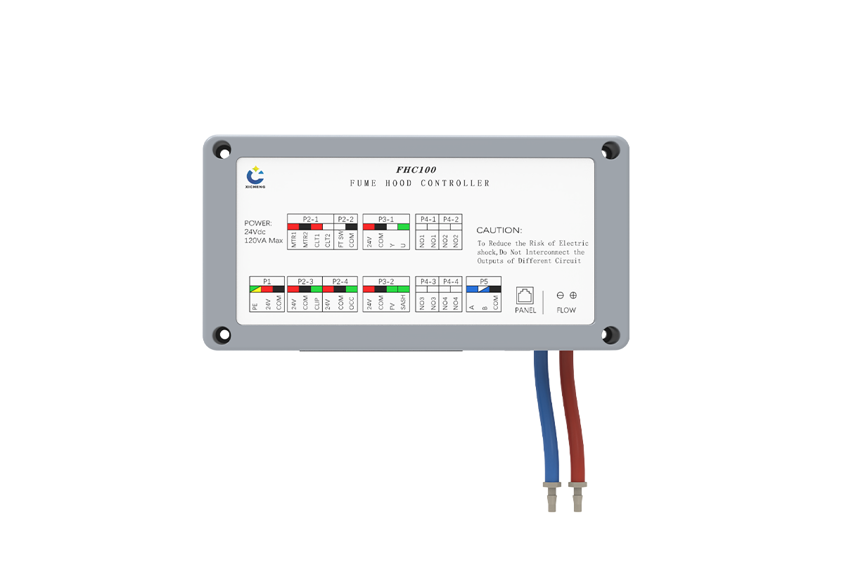
Description
This automatic sash fume hood controller coordinates variable exhaust airflow with powered sash movement and the approved safety sequence. It can use face-velocity or sash-position demand, command a compatible exhaust-airflow device, and interface with the sash motor and safety inputs. Within XICHENG’s laboratory airflow controls and actuators range, it is the combined airflow-and-sash option rather than a sash drive alone.
- Face-velocity or sash-position input for fume hood VAV demand
- Automatic sash motor interface with configurable opening and closing operation
- Connections for the damper actuator, anti-pinch input, occupancy input, foot switch, operator panel, and airflow sensing
- Emergency exhaust, energy-saving, audible/visual alarm, and Modbus RTU functions
The controller coordinates these functions but does not replace the fume hood, sash motor and transmission, exhaust damper or air valve, airflow pickup, safety sensors, or field commissioning. The supplied configuration is defined for the approved hood, airflow device, sash mechanism, interfaces, and control sequence.
Product Overview
Where The Automatic-Sash Fume Hood Controller Fits
The controller is intended for laboratory fume hoods whose exhaust demand changes with the sash opening and whose sash is moved by a powered mechanism. It receives the selected face-velocity or sash-position signal, uses the configured airflow-detection path, and commands the exhaust-airflow device so the hood can operate at its defined demand state. At the same time, its automatic-sash motor interface coordinates powered opening or closing with the project’s occupancy, foot-switch, anti-pinch, alarm, and manual-operation requirements. This combination separates it from a controller that only regulates a damper and from an operator that only moves the sash.
How Airflow And Sash Motion Work In One Control Loop
Opening the sash changes the hood opening area and therefore the exhaust airflow required to maintain the project face-velocity target. The control strategy can use a face-velocity sensor or a sash-position signal to establish demand, then adjust the compatible damper actuator while airflow or differential-pressure information supports control and commissioning. The automatic-sash function adds a second controlled mechanism: the sash motor. Its opening speed, closing speed, permissions, sensor inputs, and safety stops must be coordinated with the airflow sequence so that sash movement never substitutes for verified exhaust performance.
Product And System Boundary
The controller is one engineered component within the fume hood and laboratory ventilation system. It does not by itself include the sash motor, transmission, anti-pinch sensor, occupancy sensor, local panel, exhaust damper, Venturi valve, fan, variable-frequency drive, ductwork, BMS programming, or field commissioning unless those items are explicitly listed in the approved quotation. It also does not perform room-level supply/exhaust tracking or room differential-pressure control. A project-ready package therefore identifies the controller revision, supplied accessories, control sequence, electrical interfaces, mechanical interfaces, field wiring, airflow balancing, face-velocity verification, sash safety testing, and final acceptance responsibility.
Product Selection Summary
Choose This Controller When
Choose the automatic-sash fume hood controller when a powered sash and variable exhaust airflow need to operate as one coordinated hood sequence. The system needs a defined face-velocity or sash-position control input, a compatible exhaust damper or air valve, and a sash mechanism matched to the motor drive, travel, limits, manual release, and anti-pinch protection. Normal, energy-saving, emergency, alarm, and fault states are configured separately so automatic closing becomes part of the hood safety and airflow strategy rather than an isolated timer function.
- The hood requires both VAV/face-velocity control and automatic sash movement.
- The sash motor, safety sensors, foot switch, occupancy input, and local panel can be coordinated through an approved sequence.
- The exhaust-airflow device can accept the selected command and provide the required feedback.
- Modbus RTU or local I/O is required for project-defined monitoring and interlocks.
- Airflow, face velocity, alarms, sash travel, safety inputs, and failure behavior will be commissioned on site.
Check The Sash And Exhaust Interfaces
Horizontal, combination, multi-panel, unusually heavy, unbalanced, or mechanically modified sashes may need a different motor, transmission, sensor arrangement, or control method. The exhaust-device actuator also needs confirmed power, signal, torque, travel, rotation direction, feedback, and failure position. For hazardous processes, UV equipment, fire/smoke functions, emergency power, or defined containment duties, verify the complete hood system because the controller interfaces alone do not establish certification or a universal safety function.
Information Needed To Configure The Controller
For each hood, provide the hood type, sash arrangement, opening dimensions, travel, weight, balancing method, motor and transmission concept, safety-sensor plan, target face velocity, minimum through emergency airflow states, airflow-control device, available duct pressure, actuator signals, power supply, operating modes, alarm priorities, BMS point list, and installation responsibility. XICHENG can then recommend the controller revision, input method, accessories, interface allocation, drawings, commissioning requirements, and commercial price for that hood.
Key Specifications
The specification below identifies the confirmed control functions and interfaces for the automatic sash fume hood controller. Because each unit is configured for a non-standard hood and control sequence, signal ranges, connected loads, terminal allocation, supplied sensors, motor package, damper actuator, and BMS points must be fixed in the approved submittal rather than assumed from the product-family name.
Controller And Interface Data
| Selection Field | Available / Confirmed Configuration |
|---|---|
| Product type | Automatic-sash fume hood controller with VAV/face-velocity and safety-control functions |
| Primary control input | Project-selected face-velocity sensor signal or sash-position signal |
| Exhaust control | Commands a compatible damper actuator to regulate fume hood exhaust demand |
| Airflow detection | Built-in high-precision airflow-detection function with configurable differential-pressure coefficient; range and accuracy are project-specific |
| Automatic sash control | Built-in sash-motor control with configurable opening and closing speed |
| Safety and operation inputs | Visible interfaces for anti-pinch, occupancy, foot switch, sash position / face velocity, and local operator panel |
| Operating functions | Multiple project-configured modes including energy-saving and one-touch emergency exhaust |
| Alarm | Built-in audible/visual alarm when configured exhaust airflow falls below the safe threshold |
| Communication | RS-485 with Modbus RTU support |
| Power shown on drawing | 24 VDC; the interface drawing also shows 120 VA Max, so connected-load capacity and controller consumption must be identified separately in the approved electrical schedule |
| Damper actuator compatibility | Can be configured for different actuator brands after supply, command, feedback, torque, travel, direction, and fail-state review |
| Configuration | Built to the approved hood, sash, sensor, motor, airflow device, control sequence, I/O, BMS, and commissioning schedule |
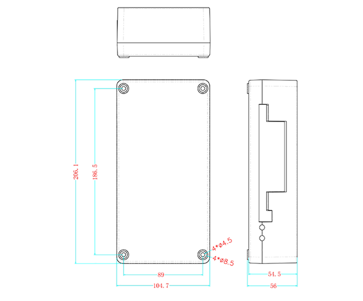
Controller Dimensions And Mounting Pattern
The drawing separates enclosure dimensions from mounting-hole spacing. Use the full drawing when preparing a backplate or service-access layout; the 188.5 mm and 89 mm values are mounting centers, not overall enclosure dimensions.
| Dimension Item | Drawing Value | Type | Layout Use |
|---|---|---|---|
| Overall height | 206.1 mm | Enclosure | Vertical space envelope |
| Overall width | 104.7 mm | Enclosure | Horizontal space envelope |
| Overall depth | 56 mm | Enclosure | Panel depth and service clearance |
| Body depth | 54.5 mm | Enclosure body | Body projection shown in side view |
| Vertical mounting centers | 188.5 mm | Mounting | Top-to-bottom fixing-hole spacing |
| Horizontal mounting centers | 89 mm | Mounting | Left-to-right fixing-hole spacing |
| Mounting-hole callouts | 4 x diameter 4.5; 4 x diameter 8.5 | Drawing callout | Confirm fastener and recess details against the issued drawing |
Allow additional clearance for removable connectors, tubing, communication cable, motor wiring, actuator wiring, and access to the local panel connection. The production drawing and wiring revision supplied for the order govern fabrication and field installation.
Control Inputs And Operating Functions
Face-Velocity Or Sash-Position Demand
The controller can be configured around either a face-velocity sensor signal or a sash-position signal. A face-velocity strategy uses measured air velocity at the hood opening as the primary controlled variable. A sash-position strategy relates the opening condition to the exhaust demand defined during engineering and commissioning. These are different control paths, so the quotation must identify the selected sensor, signal type, location, calibration method, setpoints, and fallback state. The presence of both `FV` and `SASH` labels on the interface drawing does not by itself define simultaneous dual-sensor operation.
Airflow Detection And Damper Command
Built-in airflow detection and a configurable differential-pressure coefficient support the exhaust-control loop. The controller compares the configured demand with the available airflow information and commands the compatible damper actuator through the approved output and feedback interfaces. Reliable control still depends on the airflow pickup, tubing, duct geometry, available pressure, damper authority, actuator travel, and field calibration. An actuator position or an uncalibrated pressure signal must not be accepted as proof that the required face velocity has been achieved.
Operating Modes, Emergency Exhaust And Alarm
The available configuration includes multiple operating modes, an energy-saving function, one-touch emergency exhaust, and an audible/visual alarm when exhaust airflow is below the configured safe threshold. The project sequence should state how normal, energy-saving, emergency, automatic-sash, manual, alarm, and fault commands are prioritized. It should also define the alarm delay, acknowledgement, reset condition, damper response, sash response, fan or VFD coordination, and BMS status. This prevents an energy-saving or automatic-closing command from overriding a higher-priority containment or safety requirement.
Control And Communication Interfaces
The interface groups visible on the controller provide a practical starting point for the controls schedule. Their final use depends on the hardware revision and project configuration, so the approved terminal drawing must accompany the supplied unit.
| Interface Group | Visible Labels | Project Decision |
|---|---|---|
| Automatic sash motor | MTR1, MTR2, CLT1, CLT2 | Confirm motor, direction, limit/feedback function, connected load, speed setting, and fail behavior |
| Local command | FT SW, COM | Define foot-switch action, permissions, priority, and manual-operation sequence |
| Damper actuator | 24V, COM, Y, U | Confirm actuator supply, command, feedback, travel, torque, direction, and loss-of-signal behavior |
| Safety inputs | 24V, COM, CLIP; 24V, COM, OCC | Confirm anti-pinch and occupancy sensor types, logic, delay, supervision, and fault response |
| Airflow / sash inputs | AO1, COM, FV, SASH; FLOW ports | Identify primary input, airflow pickup, signal range, coefficient, calibration points, and acceptance method |
| Local interface | PANEL | Confirm panel model, cable, displayed values, user permissions, alarm indication, and supplied scope |
| Communication | A, B, COM | Confirm RS-485 topology, Modbus RTU address, speed, point list, termination, and BMS responsibility |
| Configurable outputs | NO1, NO2, NO3, NO4 groups | Assign status, lighting, fault, UV, fan, or other approved functions and verify contact ratings on the issued wiring schedule |
Prepare the sequence of operations and point list before final I/O allocation. This is especially important when the same hood includes automatic sash movement, occupancy logic, lighting or UV control, fan enable, alarm reporting, and emergency exhaust, because each command requires a defined priority and safe response.
Automatic Sash And VAV Control Architecture
One Controller, Two Controlled Mechanisms
The automatic sash fume hood controller coordinates an exhaust-airflow device and a powered sash, but the two outputs serve different purposes. The damper actuator changes the exhaust path to meet the configured airflow demand. The sash motor changes the hood opening through the approved mechanical transmission. Coordinating them in one control platform can simplify the sequence and make operating modes consistent, yet neither mechanism can be used as a substitute for the other. Closing the sash does not prove that the exhaust is safe, and opening the damper does not prove that the sash mechanism is safe to move.
Automatic Sash Motor And Movement Sequence
The built-in motor-control function allows opening and closing speed to be configured for the selected sash assembly. A complete sequence should define who or what may request motion, the permitted travel, upper and lower limits, stopping behavior, manual release, recovery after power loss, and the response to a conflicting command. The motor, transmission, counterbalance, sash mass, friction, guides, and available mounting space must be reviewed together. Where a foot switch or operator-panel command is used, its action and priority should be stated explicitly rather than inferred from the interface label.
Occupancy And Anti-Pinch Inputs
The controller drawing provides separate interface groups for occupancy and anti-pinch inputs. Occupancy information can support a project-defined energy-saving or automatic-closing sequence, while the anti-pinch input is used to stop or modify motion when the approved safety device is activated. The page does not assign a sensor technology, detection distance, delay, safety category, or fail-safe performance because these depend on the selected devices and control design. Commissioning must prove sensor coverage, trigger response, restart behavior, manual override, alarm indication, and the result of an open, shorted, unavailable, or obstructed sensor condition where those faults are monitored.
Coordinating Sash Motion With Airflow Safety
Airflow demand can change rapidly while the sash is moving, so the project sequence should define how the controller handles acceleration of the exhaust response, low-airflow alarm, emergency exhaust, manual sash movement, and sensor disagreement. The face-velocity or sash-position input, airflow pickup, damper actuator, sash motor, and alarm thresholds must be commissioned as one hood system. Acceptance should include movement through representative openings, confirmation of actual airflow and face velocity, verification of limits and anti-pinch response, and testing of normal, energy-saving, emergency, alarm, communication-loss, sensor-fault, and power-restoration states.
Damper, Sensor And System Compatibility
Exhaust damper And Actuator Interface
The controller can be configured to work with different actuator brands, but compatibility is established by engineering review rather than brand name. Confirm the actuator supply, command signal, feedback signal, required torque or linear force, rotation or stroke, direction, running behavior, mounting interface, and response after loss of power or command. The same review determines whether the controller will serve a VAV butterfly damper, a VAV Venturi valve, or another approved exhaust-airflow device. Valve-body material, size, pressure range, airflow range, and chemical suitability belong to the selected airflow device, not to the controller.
Face-Velocity, Sash-Position And Airflow Inputs
The selected control input must match the hood geometry and the project’s verification method. A face-velocity sensor directly supports a velocity-based strategy at the hood opening. A sash-position sensor establishes an opening-related demand that still requires airflow and face-velocity confirmation during commissioning. The controller’s airflow-detection function also requires a correctly located pickup, intact tubing, suitable duct conditions, and project calibration. Sensor supply, output range, cable, mounting location, zero/span procedure, alarm limits, and replacement strategy should be included in the submittal.
Fan, VFD, BMS And Laboratory Airflow Coordination
The automatic-sash controller regulates the individual hood sequence; it does not replace the exhaust fan, fan VFD, duct static-pressure control, room supply/exhaust tracking, or room-pressure controller. If hood demand changes are transmitted to a central exhaust system, define how damper position, measured airflow, emergency exhaust, fan enable, alarm, and communication status are shared. Modbus RTU can support approved BMS integration, while hardwired outputs may be assigned to project-specific status, fault, lighting, UV, or other functions. The final point list and control narrative determine which interfaces are used.
Controller Scope Versus A Complete Automatic-Sash Package
A complete package may require the controller, operator panel, face-velocity or sash-position sensor, airflow pickup and tubing, sash motor, transmission components, limit or position devices, anti-pinch sensor, occupancy sensor, foot switch, damper actuator, airflow-control device, power supply, cables, enclosures, and field services. Only items identified in the approved quotation are included. Separating controller scope, optional XICHENG components, third-party devices, contractor-supplied items, and commissioning responsibilities prevents interface omissions during procurement.
Applications And Project Fit
Automatic-Sash Variable-Air-Volume Fume Hoods
The primary application is a laboratory fume hood where the opening changes during use, exhaust demand is regulated to a defined face-velocity or airflow condition, and powered sash movement is part of the operating sequence. The controller is relevant to new hoods and engineered control upgrades when the sash mechanism, exhaust-airflow device, sensors, motor, safety inputs, and site control system can be reviewed as one package. Research, teaching, process, and industrial laboratories may use this architecture, but the actual process hazard, containment requirement, hood construction, and ventilation design remain project-level decisions.
Energy-Saving And Safety-Control Projects
Automatic sash operation can support an energy-saving strategy by reducing the hood opening when the approved occupancy and operating conditions permit it. The controller also provides one-touch emergency exhaust and an audible/visual low-airflow alarm function. These capabilities are useful only when their priorities are defined against active work, occupancy, manual operation, anti-pinch input, airflow availability, fire or emergency commands, and BMS status. A responsible design therefore treats energy saving as a controlled operating mode, not as permission to close a sash or reduce airflow without a verified safety sequence.
When This Product Is Not The Right Controller
Do not select this product when the project only needs a damper actuator, a stand-alone sash operator, an airflow monitor, a room pressure controller, or a complete fume hood. It is also unsuitable as a certified fire/smoke control, machinery-safety controller, or universal replacement for an unknown legacy system without interface review. If the sash cannot be motorized safely, the hood has no defined VAV control strategy, the selected sensors cannot be calibrated, or the exhaust system cannot respond to changing demand, resolve those system constraints before specifying the controller.
When Another Controller Should Be Evaluated
Choose the fume hood controller with integrated VAV actuator when airflow control is required without the FHC100 automatic-sash motor task and the selected rotary or linear actuator should be integrated. Evaluate the fume hood face-velocity controller when direct velocity feedback defines the product, or the sash-position fume hood controller when resistive sash-position demand and an integrated actuator define the architecture. Use the fume hood controller for an external actuator when the controller and actuator must be supplied separately. For powered sash movement and safety control without the complete VAV/face-velocity task, evaluate the planned automatic fume hood sash controller. Compare these products by primary input, controlled device, actuator architecture, automatic-sash scope, I/O, alarm sequence, and supplied components.
Installation, Wiring And Commissioning
Mechanical And Controls Checks Before Installation
Confirm the controller mounting location, service clearance, connector access, tubing route, cable segregation, enclosure environment, and operator-panel position before fabrication. Separately review the sash motor, transmission, counterbalance, guide condition, travel limits, manual release, anti-pinch device, occupancy sensor, foot switch, and any moving-cable arrangement. For the exhaust-control loop, confirm the damper or air-valve size, actuator interface, airflow pickup, available pressure, fan/VFD strategy, and commissioning access. This precheck prevents the controls package from being approved before the mechanical sash and ventilation system can support it.
Wiring And Interface Reference
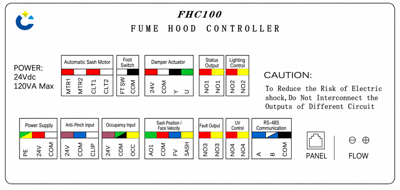
The diagram below identifies the visible FHC100 interface groups. It is a coordination reference, not a substitute for the revision-controlled wiring diagram supplied with the order. Terminal function, signal range, contact rating, cable type, shielding, overcurrent protection, earthing, and connected-load limits must be confirmed before field wiring. The diagram warning also prohibits interconnecting outputs from different circuits.
| Interface | Drawing Labels | Before Connection | Commissioning Check |
|---|---|---|---|
| Automatic sash motor | MTR1, MTR2, CLT1, CLT2 | Verify motor, supply/load, direction, limit function, wiring, and mechanical travel | Test open, close, stop, limits, manual release, power loss, and conflicting commands |
| Foot switch | FT SW, COM | Define switch type, location, user permission, and command priority | Confirm requested motion and safe cancellation under every operating mode |
| Damper actuator | 24V, COM, Y, U | Verify supply, command, feedback, torque/stroke, direction, and fail position | Stroke the device and compare command, feedback, measured airflow, and face velocity |
| Anti-pinch sensor | 24V, COM, CLIP | Verify sensor technology, coverage, logic, cable, and supervised fault condition | Test obstruction response, stopping/reversal sequence, reset, and sensor fault |
| Occupancy sensor | 24V, COM, OCC | Verify field of view, delay, output logic, and effect on energy-saving/closing commands | Test occupied, unoccupied, blocked, and failed-sensor states |
| Velocity / sash demand | AO1, COM, FV, SASH | Select the control input and confirm signal, mounting, zero/span, and calibration method | Test representative sash openings, setpoints, alarms, and fallback behavior |
| Airflow pickup | FLOW positive / negative ports | Verify pickup location, tubing polarity, leaks, coefficient, duct condition, and pressure range | Compare controller value with the approved airflow measurement and hood test |
| Operator panel | PANEL | Confirm compatible panel, cable, displayed values, permissions, and supplied scope | Verify mode command, alarm indication, acknowledgement, and access levels |
| RS-485 communication | A, B, COM | Confirm Modbus RTU address, baud rate, parity, topology, termination, and point list | Verify every mapped command, value, status, alarm, and communication-loss response |
| Configurable outputs | NO1-NO4 groups | Assign status, lighting, fault, UV, or other approved functions and verify ratings | Test each output independently; do not bridge outputs from different circuits |
Control-Sequence And Network Coordination
The controls contractor should issue a sequence of operations and point list that assigns every local and network command. At minimum, define normal, energy-saving, emergency, automatic, manual, occupied, unoccupied, low-airflow, sensor-fault, motor-fault, actuator-fault, communication-loss, and power-restoration behavior. State which command has priority, which outputs remain active, whether sash motion is permitted, how the exhaust device responds, and what the user and BMS will see. Network control should supplement rather than obscure the local safety sequence.
Functional Testing And Acceptance
Commission the installed hood as a system. Verify sensor calibration, tubing, damper travel, airflow at defined demand states, face velocity at representative sash openings, alarm threshold and delay, emergency exhaust, energy-saving transition, sash opening/closing speed, limits, anti-pinch response, occupancy logic, foot-switch behavior, local panel, hardwired outputs, Modbus points, power interruption, and recovery. Record the approved settings and test results by hood tag. Final acceptance should be based on the project ventilation and safety criteria, not on controller power-up or actuator motion alone.
How To Select And Specify The Controller
Define The Hood And Control Objective First
Start with the required operating result, not the controller model. Identify the hood type and process, sash arrangement and opening geometry, target face velocity, airflow states, exhaust-system pressure conditions, and the reason for automatic sash movement. Then choose whether direct face-velocity feedback or sash-position demand will define the primary control strategy. State how airflow is measured, which low-airflow condition creates an alarm, when energy-saving mode is permitted, what activates emergency exhaust, and how automatic sash commands interact with active laboratory work.
Match The Mechanical, Electrical And Controls Interfaces
For the sash, provide travel, mass, balance, guides, motor, transmission, limit method, manual release, anti-pinch device, occupancy sensor, foot switch, and local-control requirements. For the exhaust path, provide the airflow-control device, size, material, actuator supply, command, feedback, torque or force, rotation or stroke, fail position, available pressure, and airflow pickup. For the controls scope, identify power, panel, hardwired I/O, output assignments, Modbus RTU point list, alarm reporting, cable responsibility, and the interfaces to fan, VFD, BMS, emergency power, lighting, and UV where applicable.
Write A Tag-Level Sequence And Supply Schedule
Each hood tag should have an approved sequence covering start-up, normal use, sash movement, energy-saving operation, emergency exhaust, low airflow, obstruction, sensor failure, motor or actuator failure, communication loss, manual operation, power loss, and restoration. The supply schedule should identify the controller revision and every included sensor, motor, transmission component, panel, power supply, actuator, airflow-control device, cable, enclosure, drawing, software configuration, test, and field service. A complete schedule lets suppliers and contractors price the same scope and gives the commissioning team measurable acceptance criteria.
Technical Data, Configuration, And Documentation
Data Needed For The Final Configuration
The final configuration distinguishes built-in controller functions from values determined by the selected hardware revision and connected devices. Confirm the 24 VDC power arrangement and separate controller consumption from the connected-load capacity shown on the wiring diagram. Record the sensor signal ranges, airflow or pressure range, differential-pressure coefficient, actuator command and feedback, motor data, output contact ratings, panel interface, communication settings, environmental limits, and cable requirements. Values that are not yet known remain to be confirmed instead of being replaced with generic industry assumptions.
Mechanical coordination covers enclosure space, connector access, tubing, sash travel and load, motor and transmission, safety sensors, airflow-control device, actuator interface, and service access. Control coordination covers mode priorities, alarm limits and delays, emergency behavior, automatic-sash permissions, anti-pinch response, occupancy logic, manual operation, power failure, communication failure, BMS point mapping, and restoration. Use the same hood tags and revision references throughout so a change to the sash or airflow device is reflected in the controller configuration.
Technical Submittal And Handover Contents
Available project documentation can include the product datasheet, enclosure and mounting drawing, terminal diagram, point list, sequence of operations, wiring responsibility matrix, sensor and actuator data, airflow-control device data, sash-motor and transmission information, and panel or BMS interface details. After commissioning, retain the final settings, calibration records, airflow and face-velocity test results, automatic-sash safety test, alarm and emergency-exhaust test, network verification, as-built drawings, and operating guidance. These records make future service or replacement easier because they describe the actual installed configuration.
Related Products
Airflow-Control Devices For The Hood Exhaust Branch
The controller requires a project-selected exhaust-airflow device and actuator interface. Review the VAV butterfly damper for laboratory airflow control when a rotating-blade device suits the duct, material, pressure, airflow, and control requirements. Evaluate the VAV Venturi valve for laboratory exhaust control when the project requires its verified Venturi mechanism and corresponding size, airflow, material, and pressure characteristics. The valve or damper datasheet must be coordinated with the controller, actuator, airflow pickup, fan system, and commissioning method.
Alternative Fume Hood Controllers And Sash Components
For airflow control without powered sash operation, compare the fume hood controller with integrated VAV actuator, fume hood face-velocity controller, sash-position fume hood controller, and fume hood controller for an external actuator. When the project only requires automatic sash motion and safety inputs, review the planned automatic fume hood sash controller and the physical sensors, motor, transmission, panel, and power components under fume hood system accessories. Select by control task and supplied scope, not by model sequence alone.
Frequently Asked Questions
What does an automatic sash fume hood controller control?
It coordinates the hood’s variable exhaust-airflow demand and powered sash movement. The selected face-velocity or sash-position input establishes the airflow requirement, the controller commands a compatible exhaust damper actuator, and the automatic-sash function operates the approved sash motor within the project safety sequence. It also supports airflow detection, operating modes, low-airflow alarm, emergency exhaust, local interfaces, and Modbus RTU communication.
How is it different from a stand-alone automatic sash controller?
A stand-alone automatic sash controller focuses on opening, closing, occupancy, foot-switch, and anti-pinch tasks. The FHC100 product also performs the fume hood VAV/face-velocity control task and coordinates the exhaust-airflow device. If the project only needs powered sash movement and safety control, the planned automatic fume hood sash controller is the more direct product family. If automatic sash and airflow control must operate together, evaluate this combined controller.
Can the controller use either face velocity or sash position?
Yes, XICHENG identifies face-velocity change or sash-position sensor opening as available control inputs for this product. The project must select the intended strategy and confirm the sensor, signal, mounting, calibration, airflow measurement, setpoints, alarm threshold, and fallback behavior. The presence of both interface labels does not automatically establish a simultaneous dual-sensor sequence for every unit.
Are the sash motor, sensors, panel and damper included?
Not unless they are listed in the approved quotation. A complete project may require a sash motor, transmission, limits, anti-pinch sensor, occupancy sensor, foot switch, face-velocity or sash-position sensor, airflow pickup, operator panel, damper actuator, airflow-control device, power supply, cables, and commissioning. The scope should identify XICHENG-supplied items, third-party items, contractor-supplied items, and field-service responsibilities separately.
Can it control different damper actuator brands?
The product information states that different actuator brands can be matched. This requires confirmation of supply voltage, command and feedback signals, torque or force, rotation or stroke, direction, mechanical mounting, running behavior, and fail position. The controller should not be treated as universally compatible with an actuator solely because the actuator uses a common analog signal.
Does the anti-pinch input make the sash system certified safe?
No certification or safety category is established by the interface alone. The anti-pinch sensor, coverage, wiring, logic, stopping or reversal behavior, fault monitoring, manual release, motor, transmission, sash mechanics, and commissioning test determine the actual safety performance. The project must define and verify normal, obstructed, failed-sensor, power-loss, and recovery states against its applicable requirements.
What communication and output functions are available?
The controller supports RS-485 with Modbus RTU, and the visible wiring groups include configurable outputs associated with status, lighting, fault, and UV functions. Final point mapping, communication settings, output assignment, contact ratings, alarm reporting, and loss-of-communication behavior follow the approved hardware revision and controls schedule. A BMS connection does not replace local airflow alarm or sash-safety logic.
What must be tested during commissioning?
Commissioning should verify sensor calibration, airflow pickup and tubing, damper/actuator travel, airflow at defined operating states, face velocity at representative sash openings, alarm threshold and delay, emergency exhaust, energy-saving transition, sash opening and closing, limits, anti-pinch response, occupancy and foot-switch logic, panel operation, outputs, Modbus points, power interruption, communication loss, and restoration. Record results and final settings by hood tag.
What information is required for a project-ready quotation?
Provide the hood and process, sash geometry and mechanics, motor and transmission, safety sensors, target face velocity, minimum through emergency airflow states, selected control input, airflow-control device, actuator data, available pressure, airflow pickup, power, operating modes, alarm sequence, panel, I/O, BMS point list, quantity, destination, and required installation or commissioning services. Include hood drawings, duct layout, control schematic, point list, and sequence of operations when available.
Contact the Xicheng Engineering Team Today.
Send the fume hood and sash drawings, sash geometry and travel, motor and transmission details, face-velocity or position-control strategy, minimum through emergency exhaust airflow, airflow-control device and actuator interface, safety sensors, operating modes, power, I/O, BMS point list, alarm and failure sequence, quantity, destination, and required commissioning services. XICHENG will recommend an automatic-sash fume hood controller configuration and provide the applicable components, interface details, specifications, documentation, and commercial pricing.
🎯 Shenzhen Office: No. 34 Zhenxing Road (Shengtaian Heavy Industrial Park B), Loucun, Guangming New Dist, Shenzhen, Guangdong, China
☎️ WhatsApp: +86 181 2647 8161
📬 Engineering Mailbox: fanalax34@gmail.com