


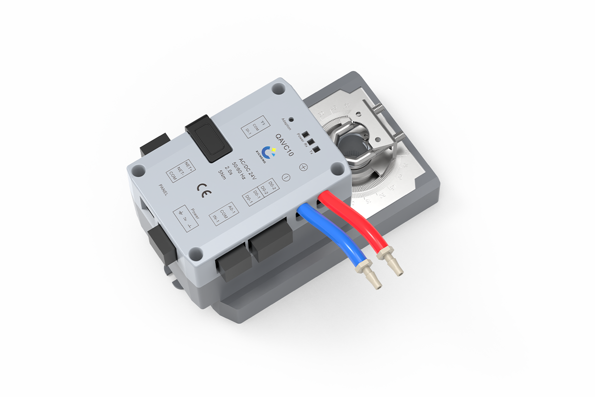
Description
This integrated duct airflow controller is configured for laboratory supply, general exhaust, fume hood exhaust, or pressure-sensitive branches that require measured airflow and fast valve movement. It combines differential-pressure sensing, control logic, and rotary or linear actuation in one assembly. Compare it with other laboratory airflow controls and actuators according to the controlled variable, valve mechanism, response requirement, and system sequence.
- Built-in differential-pressure sensing for the approved airflow pickup and coefficient
- VAV, CAV, room differential-pressure, and position-control configurations
- 5, 15, or 30 Nm rotary output for compatible 0-90-degree mechanisms, or 100 N linear output for a compatible 0-100 mm stroke
- Analog setpoint and feedback, contact and switching functions, local-panel connection, and Modbus RTU communication
The assembly provides sensing, control, and actuation; it is not a complete valve, VAV terminal, room-control system, or fume hood safety controller. Its delivered configuration is matched to the selected airflow device, mechanical interface, measurement path, signals, and project sequence.
Product Overview
Where The Integrated Airflow Controller Fits
A duct branch with a defined airflow target needs more than a motor that moves a blade or cone. It needs a measurement signal, a controller that compares the measured condition with the active setpoint, and an actuator that can reposition the airflow device quickly enough for the intended sequence. This duct airflow controller combines those three functions in one assembly, reducing the separate mounting and signal coordination required between a controller and an external actuator. Rotary configurations attach to compatible 0-90° mechanisms, while the linear configuration is intended for a compatible 0-100 mm stroke. The final choice follows the valve mechanics and required output, not the product name alone.
How The Closed-Loop Airflow Path Works
A suitable airflow-measurement element creates a differential-pressure signal as air passes through the duct or valve. The built-in sensor receives that signal, and the configured coefficient allows the controller to relate differential pressure to airflow for the selected assembly. The active demand may come from an analog airflow setpoint, a remote Modbus RTU command, a room differential-pressure input, or a position-control sequence. The controller then changes the actuator position and returns an analog value representing airflow, pressure, or actuator position according to the selected operating mode. Correct pressure-tube routing, coefficient entry, valve direction, minimum and maximum limits, and field airflow verification are therefore part of the control loop rather than optional finishing work.
Product And System Boundary
The integrated VAV controller actuator is not automatically a complete butterfly damper, Venturi valve, VAV terminal, room-pressure system, or ventilation package. The valve body, airflow pickup, pressure tubing, fan, ductwork, local panel, room sensor, door contact, power supply, BMS programming, testing and balancing, and commissioning may be separate project items unless the quotation lists them as supplied. Room-pressure operation also depends on a defined relationship between supply, exhaust, door status, pressure feedback, and override priorities. For laboratory or process exhaust, the air-stream chemistry, particulate loading, condensation risk, sensor and tubing suitability, and exposed valve materials must be reviewed before the controller is specified.
Product Selection Summary
Use these checks to determine whether the integrated controller and actuator architecture matches the airflow device, control sequence, and available field interfaces.
Choose This Controller When
- The branch requires measured VAV/CAV airflow, room-pressure input, or a defined position command.
- Integrated sensing, control, and fast actuation are preferred over a separate controller and actuator.
- The valve matches a 5, 15, or 30 Nm rotary mechanism or the 100 N linear mechanism.
- The airflow device supplies suitable measurement connections and coefficient or calibration data.
- The project can coordinate 24 V power, analog, contact, panel, switching-output, and Modbus RTU interfaces.
- Commissioning includes direction, pressure signal, coefficient, measured airflow, and mode acceptance.
Check These Conditions Before Selection
For retrofit valves, confirm the shaft or stroke, loaded torque or force, and the required position after power or communication loss. Air streams carrying corrosives, particles, moisture, or condensate need compatible exposed and connected components. For room-pressure control, define the sensor, door contact, supply/exhaust relationship, operating priorities, and acceptance criteria as one complete sequence rather than isolated I/O points.
Information Needed To Configure The Controller
For each tag, provide the application, valve and measurement data, airflow states, available pressure, control mode, shaft or stroke, output requirement, action time, air-stream and installation conditions, power, I/O, panel, Modbus points, failure sequence, quantity, and destination. Attach the valve drawing, airflow schedule, control schematic, point list, and room-pressure sequence where available. XICHENG can then recommend the controller variant, mechanical interface, accessories, included components, and commissioning tests.
Key Specifications
Controller And Interface Data
The table separates controller-level facts from valve-body and project-level performance. Airflow range, available pressure, measurement coefficient, control tolerance, and final setpoints are determined by the selected airflow device and commissioned assembly rather than by the controller enclosure alone.
| Specification | Available Product Data |
|---|---|
| Product type | Integrated duct airflow controller with differential-pressure sensing and fast rotary or linear actuation |
| Control modes | VAV airflow, CAV airflow, room differential-pressure input, or damper-position control |
| Compatible airflow-device mechanisms | Project-matched butterfly damper or Venturi air valve |
| Measurement | Built-in differential-pressure sensor for the configured airflow-measurement arrangement |
| Power supply | 24 VDC ±10%, 20 W maximum; 24 VAC ±10%, 40 VA maximum |
| Analog input | One voltage/current input for airflow setpoint or room-pressure input |
| Analog output | One voltage/current output for airflow, pressure, or actuator-position feedback |
| Dry-contact input | One input for a door contact in room differential-pressure control mode |
| Switching outputs | One output for lighting control and one output for status indication |
| Local panel | One RJ12 communication port for a compatible operator panel |
| BMS communication | RS-485 with Modbus RTU; published baud-rate range 9.6-76.8 kbps |
| Rotary actuator choices | 5, 15, or 30 Nm; 0-90° travel |
| Linear actuator choice | 100 N; 0-100 mm travel |
| Working environment | 0 to +50 °C; 10-95% RH, non-condensing |
| Storage environment | -20 to +50 °C; 10-95% RH, non-condensing |
| Configuration basis | Valve mechanics, airflow states, measurement coefficient, signals, panel, Modbus points, installation, and acceptance method |
Model, Output, And Dimension Comparison
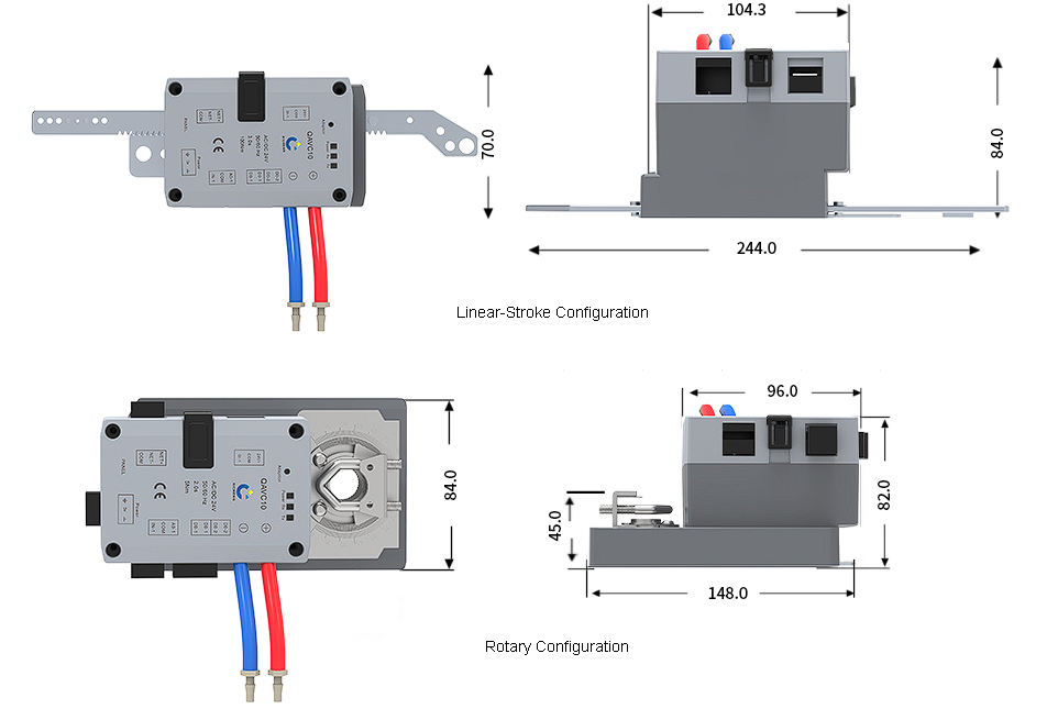
Use the drawing and table together. The faster or higher-output variant is not automatically the correct choice: the valve mechanism, required output with engineering margin, shaft or linkage geometry, available mounting space, and approved operating sequence determine the selection.
| Configuration | Motion | Output | Travel | Action Time | Dimensions And Interface |
|---|---|---|---|---|---|
| QAVC10-5 | Rotary | 5 Nm | 0-90° | 2.0 s | 148 × 84 × 82 mm; 15.5 mm shaft diameter |
| QAVC10-15 | Rotary | 15 Nm | 0-90° | 5.0 s | 165 × 84 × 85 mm; 19.5 mm shaft diameter |
| QAVC10-30 | Rotary | 30 Nm | 0-90° | 9.0 s | 165 × 84 × 85 mm; 19.5 mm shaft diameter |
| QAVC10-L | Linear | 100 N | 0-100 mm | 3.0 s | 244 × 70 × 84 mm; linear linkage |
These action times describe the actuator variants shown in the product data; they are not a guarantee of complete duct-system stabilization. Actual control performance also depends on the valve, airflow pickup, pressure signal, coefficient, duct pressure, fan response, command source, parameter settings, mechanical load, and commissioning. The final technical schedule should state which values apply to each valve tag and identify any field data still required for approval.
Control Modes And Operating Functions
Measured VAV And CAV Airflow Control
In VAV operation, the active airflow setpoint can change through the configured analog input or Modbus RTU command. The variable air volume controller compares that demand with the airflow value derived from the differential-pressure signal and repositions the valve until the measured condition follows the commissioned setpoint. In CAV operation, the target remains at the selected constant value while the same closed loop corrects for operating changes within the capability of the complete valve and duct arrangement. The minimum and maximum limits, coefficient, sensor zero, feedback scaling, and alarm or override behavior must be recorded by valve tag; a generic controller setting cannot replace the airflow schedule.
Room Differential-Pressure And Position Control
For a room-pressure application, an external pressure signal can be used as the analog control input, and the dry-contact input can receive a door-status signal. The controller can then adjust the connected supply or exhaust airflow device according to the approved pressure sequence. This mode does not turn one controller into a complete room-control system: the pressure sensor location and range, door logic, supply/exhaust relationship, normal and emergency priorities, fan response, and recovery after a door event must be engineered and tested together. Position-control mode is available where a command should define valve position rather than measured airflow. Because position is not an airflow measurement, the project must state whether airflow feedback, balancing, or another supervisory check remains required.
Local Setup Controls And Airflow Sensor Connections
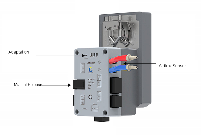
The enclosure provides an Adaptation control for setup and an accessible manual release for mechanical positioning. The paired red and blue pressure connections route the differential-pressure signal to the built-in airflow-sensing path. Before adaptation or parameter entry, verify the valve’s safe travel, mechanical end limits, linkage, direction, pressure-tube routing, and selected coefficient. Manual release is intended to help position or inspect the mechanism; it does not establish a commissioned airflow value and should not be treated as a substitute for an approved isolation or lockout procedure.
Analog, Panel, Switching, And Modbus Interfaces
The available interfaces allow the integrated airflow controller to work as a local closed-loop device while exchanging setpoint, feedback, status, and configuration information with the wider project. Their final use is mode-dependent. Signal type, scaling, common reference, output assignment, Modbus parameters, cable requirements, and loss-of-signal behavior must be defined in the I/O schedule rather than inferred from the connector label.
| Interface | Documented Use | Project Checks |
|---|---|---|
| Analog input | Airflow setpoint or room differential-pressure input | Voltage/current type, range, scaling, source, common, priority, and fault behavior |
| Analog output | Airflow, pressure, or actuator-position feedback | Selected feedback variable, scaling, receiving device, common, and acceptance tolerance |
| Dry-contact input | Door contact for room-pressure mode | Contact state, debounce, priority, delay, alarm, and recovery sequence |
| Switching output 1 | Lighting control | Interposing relay, load rating, local override, and electrical responsibility |
| Switching output 2 | Status indication | Status definition, normal/fault logic, receiving point, and fail state |
| RJ12 panel port | Compatible local operator panel | Panel model, cable, display functions, access level, and supplied scope |
| RS-485 BMS port | Modbus RTU remote setting and monitoring | Address, 9.6-76.8 kbps selection, serial format, register map, write access, termination, and communication-loss behavior |
Integrated Fast Actuator Options
The integrated actuator is part of the airflow-control architecture. Its motion, output, action time, interface, and envelope must match the valve and control sequence. Select the mechanism first, then verify output and speed against the loaded valve.
Rotary Actuator Configurations
Available 0-90° Outputs
Three rotary configurations cover different loads. The 5 Nm version moves 0-90° in 2.0 seconds with the published 15.5 mm shaft interface. The 15 and 30 Nm versions use the larger enclosure and 19.5 mm shaft interface, with 5.0- and 9.0-second action times. Each still requires a matched rotary valve mechanism.
Rotary Selection Checks
Determine torque from valve data or a documented calculation covering geometry, seal friction, bearings, differential pressure, coupling losses, deposits, orientation, and design margin. Confirm adapter, anti-rotation support, direction, end stops, and service clearance. The fastest version is unsuitable if it cannot move the loaded valve; a higher-output version still needs an action time compatible with the sequence.
Linear-Stroke Actuator Configuration
100 N Output And 0-100 mm Travel
The linear version provides 100 N push/pull output over 0-100 mm in 3.0 seconds. It requires a compatible translating linkage on the selected Venturi or other approved airflow device. Its 244 × 70 × 84 mm envelope includes the long linkage shown in the drawing, so duct, insulation, access, and supports must clear the complete stroke.
Linear Selection Checks
Verify force across the full travel, then confirm starting point, alignment, connection geometry, direction, end limits, side loading, return forces, and disconnected-linkage behavior. Parameter limits should prevent driving against a stop. If the valve requires different travel, force, fail action, or mounting, use an external-actuator architecture.
How To Choose Between Integrated Rotary And Linear Motion
Use rotary output for a rotating shaft and linear output for a translating cone or linkage. Compare output, travel, time, envelope, connection, environment, and service access, then verify that pickup and coefficient belong to the same valve. If an existing or specified fail-safe actuator must be retained, evaluate the duct airflow controller for an external actuator instead.
Airflow Device And System Compatibility
Butterfly damper Integration
A VAV butterfly damper normally uses a rotating shaft. Match shaft, direction, torque, end stops, coupling, anti-rotation support, and clearance to the controller variant. The loop also needs a compatible measurement element and coefficient; blade position alone does not establish airflow. Valve size, material, seals, leakage, pressure, connection, and chemical resistance remain damper-schedule fields.
Venturi Air Valve Integration
A VAV Venturi valve may use a translating cone, so evaluate the linear configuration only when its output, travel, linkage, and time match the valve. Pressure behavior, airflow range, calibration, material, coating, and connection remain valve-specific. Use an external-actuator architecture when the valve supplier defines another actuator or interface.
Airflow Measurement And Air-Stream Suitability
Airflow value quality depends on the measurement element, tap location, tubing, coefficient, duct profile, and setup. Confirm pressure routing from the valve drawing, prevent kinks and leaks, and establish zero and coefficient before balancing. Dirty, corrosive, wet, or condensing exhaust requires separate review of the pickup, tubing, sensor path, controller location, and valve components.
Controller Scope Versus A Complete Control Package
The unit supplies the controller, differential-pressure sensing, and selected integrated actuator. A complete package may also require the valve, pickup, tubing, panel, room sensor, door contact, relays, power, fan/VFD interface, network, BMS programming, installation, TAB, and testing. The quotation must classify each as included, optional, by others, or pending confirmation.
Applications And Project Fit
Supply And Exhaust Duct Airflow Control
The principal application is a duct branch whose airflow must follow a fixed or variable setpoint through a matched butterfly damper or Venturi air valve. Examples include laboratory supply air, general exhaust, equipment-ventilation branches, make-up air, and other ventilation duties where actual airflow is measured and the valve mechanism suits one of the integrated actuator configurations. The airflow schedule should define every operating state rather than only a nominal value, because minimum, normal, maximum, standby, purge, or emergency demand may come from different parts of the controls sequence.
Equipment Exhaust And Room-Pressure Participation
The air volume controller can regulate a branch serving an enclosure, process connection, or fume hood when the airflow setpoint is provided by the approved equipment or supervisory control sequence. It does not directly become a face-velocity controller merely because the branch serves a fume hood. In room-pressure applications, an external pressure signal and door contact can influence the connected supply or exhaust valve, but the room-level design must still coordinate all relevant airflows, pressure sensing, fan response, door events, alarms, and emergency priorities. Use the product as a field airflow-control element within that architecture, not as a substitute for the complete room controller or system narrative.
When This Product Is Not The Right Controller
Do not use this product as a fire damper, smoke damper, certified isolation device, passive backdraft damper, liquid valve actuator, or stand-alone room pressure monitor. It is also not the first choice when the project only needs a simple on/off or proportional motor without airflow measurement, when an existing actuator must remain, or when the specified fail-safe behavior requires an actuator architecture not available in the documented variants. Highly contaminated, corrosive, wet, or condensing air streams require a component-level suitability review; the product name alone cannot establish compatibility.
When Another Controller Should Be Evaluated
Evaluate the duct airflow and pressure controller for external actuators when a separate controller must drive an actuator selected by the valve supplier or retained during retrofit. Evaluate the planned VAV airflow and pressure controller only when its documented pressure/airflow architecture, integrated actuator, I/O, and application match the design. For direct fume-hood face-velocity or sash-demand control, use the fume hood controller family rather than treating a duct airflow setpoint controller as the hood safety controller. Compare products by control input, measurement method, actuator architecture, output, I/O, communication, scope, and commissioning method.
Installation, Wiring, And Commissioning
Mechanical And Electrical Checks Before Installation
Confirm the variant against the valve tag before mounting. For rotary assemblies, check shaft, torque, direction, travel, coupling, anti-rotation support, and setup access. For the linear assembly, check the full linkage path, load, alignment, connection, end limits, and clearance around the 244 mm length. The mechanism must move without binding before coupling or energizing the actuator.
Install the pickup and tubing from the final valve drawing. Confirm airflow direction, pressure routing, tube condition, leak-free connections, contamination precautions, and access for zero checks. Keep the controller within its ambient limits. Provide the specified 24 V source and coordinate signal separation, grounding, commons, shielding, termination, and field-device ratings.
Wiring Terminal Reference
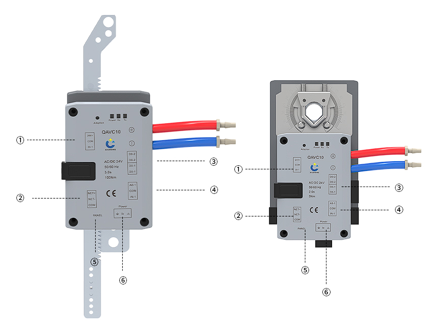
The numbered drawing identifies the main interface groups on both configurations. Use the final version-specific sheet for terminal order, polarity, conductor size, shielding, contact ratings, and protection.
| Callout | Interface Group | Documented Function And Project Check |
|---|---|---|
| 1 | Digital input | Door-contact input used in room differential-pressure mode; define contact state, sequence priority, delay, alarm, and recovery. |
| 2 | RS-485 BMS | Modbus RTU network connection; confirm polarity, common, cable, termination, address, baud rate, serial format, point map, and loss-of-communication behavior. |
| 3 | Switching outputs | Lighting-control and status outputs; confirm assignment, electrical rating, interposing relay, normal/fault logic, and receiving equipment. |
| 4 | Analog input/output | Airflow or room-pressure setpoint input and airflow, pressure, or position feedback; confirm voltage/current type, scaling, common, source, destination, and active mode. |
| 5 | RJ12 panel port | Connection for the compatible local operator panel; confirm panel model, cable, display functions, permissions, and supplied scope. |
| 6 | 24 V AC/DC power | Controller and integrated-actuator supply; size the source for the selected configuration and verify voltage, polarity where applicable, common, grounding, and protection. |
Control And Communication Coordination
Use one point schedule for every command, feedback, contact, output, panel function, and Modbus point on a valve tag. Define setpoint ownership, local/remote priority, feedback by mode, and behavior after signal or network loss. Agree register map, write permissions, units, scaling, polling, alarms, and restart behavior with the integrator. Network commands must respect mechanical and commissioned airflow limits.
Adaptation, Functional Testing, And Acceptance
After prechecks, establish safe travel and run the version-specific setup. Verify direction, end positions, sensor zero, tubing, coefficient, limits, analog scaling and feedback, door contact, outputs, panel, Modbus, and power-cycle behavior. Test each mode before transitions between VAV, CAV, room-pressure, position, standby, or override states.
Acceptance must use measured results. Compare airflow with calibrated field measurements at required states; for room-pressure work, test closed-door stability, door events, supply/exhaust interaction, recovery, alarms, and overrides. Record setpoints, coefficient, actuator variant, direction, scaling, Modbus settings, results, and approved deviations. Actuator movement, stable position, or a network read alone does not prove the required airflow or room response.
How To Select And Specify The Controller
Define The Controlled Variable And Operating States
Start with the result the branch must maintain. Define VAV demand source and range, CAV values, room-pressure signal and door response, or position range and airflow verification. List applicable minimum, normal, maximum, standby, purge, and emergency states with priorities and transitions. One analog or Modbus setpoint should not represent several undefined modes.
Match Measurement, Valve Mechanics, And Actuator Output
Select the valve and measurement arrangement before the controller variant. Record valve, airflow and pressure data, pickup orientation, coefficient, tubing, straight-run needs, and verification method. Then match shaft or linkage to output, travel, time, envelope, and interface. Specify the required function and mechanics, not only the SKU.
Confirm Interfaces, Sequence, And Responsibility
Complete the tag with power, analog scaling and feedback, contacts, outputs, panel, Modbus, and signal/power-loss behavior. Assign responsibility for valve, pickup, tubing, controller, sensors, power, relays, BMS, fan interface, installation, TAB, setup, testing, and records. Resolve conflicts among the control narrative, I/O schedule, drawings, parameters, and test procedure before production or installation.
Technical Data, Configuration, And Documentation
Data Needed For The Final Configuration
Product data establishes the available control modes, 24 V power, interfaces, Modbus RTU, environmental limits, and four actuator configurations. Each tag also needs its airflow, pressure, valve, measurement coefficient, tubing, load, signal scaling, output, panel, BMS, failure-state, and acceptance data. Recording these values on the airflow-control schedule prevents a family-level description from being mistaken for the selected configuration.
Update the configuration reference when the enclosure, actuator, terminals, firmware, panel, airflow device, or control sequence changes. A drawing for one output or hardware version does not describe another version. Identifying the selected configuration and revision keeps purchasing, panel building, installation, controls, and TAB work aligned.
Technical Submittal And Handover Contents
Available documentation can include the applicable datasheets, valve schedule, dimension and linkage drawings, pickup and tubing diagram, power and I/O schedule, wiring, panel data, Modbus points, control sequence, parameters, installation information, and commissioning procedure. After commissioning, retain the final settings, coefficient, scaling, network data, TAB and functional-test records, and maintenance instructions for future service.
Related Products
Related Airflow-Control Devices
Pair the controller with an airflow device whose mechanical interface and measurement data can be approved as one assembly. A VAV butterfly damper provides the rotating-blade path for a compatible rotary configuration, while a VAV Venturi valve can be evaluated where its cone or linkage, airflow data, and pressure behavior suit the project. For a broader view of available mechanisms, materials, and control approaches, review the laboratory airflow control category before selecting the controller output.
Related Controller Architectures
Use the planned duct airflow and pressure controller for external actuators when the project must retain or separately select the actuator. Compare the planned VAV airflow and pressure controller only after its pressure/airflow control architecture and I/O have been matched to the application. Where a laboratory fume hood needs direct face-velocity or sash-demand control, review the fume hood controller with integrated VAV actuator instead. These products may all move an airflow device, but their control input, measurement objective, mechanical architecture, local functions, and commissioning criteria are not interchangeable.
Frequently Asked Questions
What does a duct airflow controller control?
A duct airflow controller receives a setpoint or control signal, measures the differential pressure associated with airflow, and moves a connected airflow device to reduce the difference between demand and the measured condition. This integrated product combines the controller, differential-pressure sensing path, and a fast rotary or linear actuator. The final controlled airflow still depends on the valve, measurement element, coefficient, available pressure, fan, duct conditions, setup, and field verification.
Is the controller a complete butterfly damper or Venturi air valve?
No. The product combines the controller with an integrated actuator configuration. A butterfly damper or Venturi air valve may be supplied as part of a project-specific package, but the valve body, material, size, connection, airflow range, pressure behavior, measurement element, leakage, and chemical-resistance requirements remain separate selection fields. The quotation identifies whether the valve, pressure tubing, local panel, sensors, installation, balancing, and commissioning are included.
Can the same controller provide VAV, CAV, room-pressure, and position control?
The available functions include variable airflow, constant airflow, room differential-pressure input, and valve-position control modes. A configured installation does not normally use every mode as one simultaneous default. Define the active input, setpoint source, feedback value, limits, priorities, transitions, and failure behavior for the selected sequence. Room-pressure operation also needs an external pressure signal and a complete supply/exhaust and door-event sequence.
How are the rotary and linear actuator configurations selected?
Choose motion from the valve mechanism first. A rotating shaft requires a compatible 0-90° rotary configuration, available at 5, 15, or 30 Nm. A translating linkage can be evaluated against the 100 N, 0-100 mm linear configuration. Then check loaded torque or force, action time, shaft diameter or linkage, direction, end limits, enclosure dimensions, service space, environmental location, and the valve manufacturer’s approved mechanical interface.
Can it be used with both butterfly dampers and Venturi air valves?
Yes, XICHENG identifies both mechanisms as product applications, but compatibility is conditional. A butterfly damper must match the rotary shaft, torque, rotation, and airflow-measurement arrangement. A Venturi valve must match the selected linear or other approved mechanism, travel, force, linkage, and valve calibration. The controller’s interface options do not make every butterfly or Venturi product mechanically, pneumatically, or chemically interchangeable.
What power, analog, panel, and BMS interfaces are available?
The controller uses 24 VDC or 24 VAC power. Available interfaces include one voltage/current analog input, one voltage/current analog output, one dry-contact door input, two switching outputs for lighting and status, an RJ12 local-panel port, and an RS-485 port supporting Modbus RTU. Confirm the signal ranges, scaling, terminal order, contact ratings, panel model, register map, serial settings, wiring, and communication-loss behavior for the selected hardware.
Does the controller replace a room-pressure controller or fume-hood controller?
Not automatically. It can use a room differential-pressure signal to control a connected supply or exhaust airflow device, but complete room pressure control may require additional controllers, sensors, door logic, airflow tracking, alarms, and supervisory coordination. It can also regulate an exhaust branch serving a fume hood when another device provides the approved airflow demand, but direct face-velocity or sash-demand safety control belongs to a dedicated fume hood controller.
What information is required for a project-ready quotation?
Provide each tag’s application, control mode, airflow states, available pressure, valve type and size, measurement element and coefficient, pressure tubing, shaft or stroke, torque or force, action-time requirement, air-stream conditions, installation orientation, 24 V supply, analog input and feedback, contacts and outputs, local panel, Modbus points, failure sequence, quantity, destination, drawings, and commissioning requirements. XICHENG will use these details to recommend the configuration, accessories, interfaces, included components, documentation, testing services, and price.
Contact the Xicheng Engineering Team Today.
Send the airflow schedule, valve and measurement-element drawings, shaft or linkage data, control mode, pressure-signal arrangement, I/O and Modbus requirements, installation conditions, and commissioning requirements. XICHENG will recommend a duct airflow controller and actuator configuration and provide the applicable accessories, interface details, test requirements, and professional quotation within 24 hours.
Shenzhen Office: No. 34 Zhenxing Road (Shengtaian Heavy Industrial Park B), Loucun, Guangming New Dist, Shenzhen, Guangdong, China
WhatsApp: +86 181 2647 8161
Engineering Mailbox: fanalax34@gmail.com