


Description
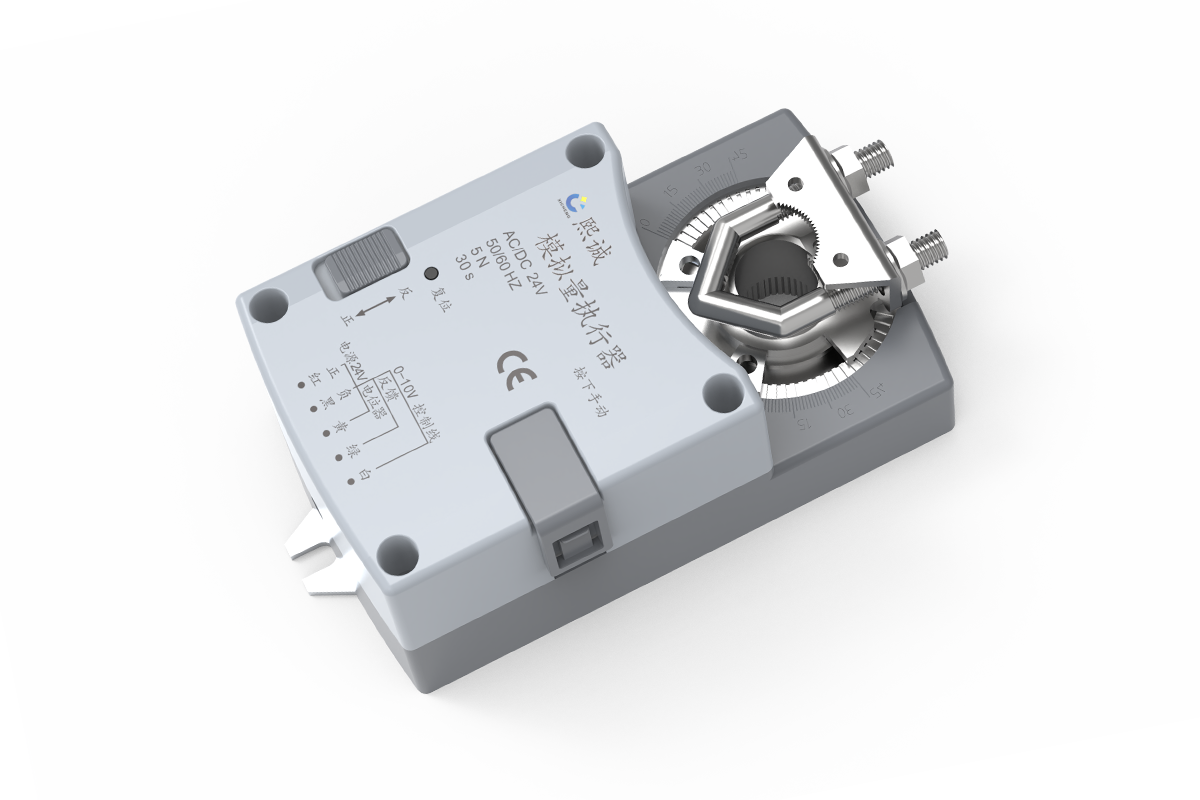
This modulating damper actuator converts a proportional analog demand into controlled rotary movement for HVAC terminal, AHU, supply, return, and exhaust dampers. Available configurations cover 5-30 Nm torque and 30-120 second travel. It is the standard proportional family within XICHENG’s HVAC controls and damper actuators range, distinct from the faster laboratory airflow actuator families.
The family combines compact 5 Nm and 10 Nm configurations with a larger 30 Nm option. Available travel times range from 30 to 120 seconds per 90 degrees, so the selection can balance damper torque and normal positioning speed without moving into the separate fast-response actuator family. The final unit is configured for the required command signal and position-feedback range.
This actuator controls shaft position; it does not measure airflow, duct pressure or face velocity. A project that closes the loop on one of those variables still needs the appropriate sensor and controller. The actuator also has no documented spring-return or network-communication function, so power-loss behavior and supervisory communication must be solved elsewhere when the sequence requires them.
Product Selection Summary
This proportional damper actuator family is a good starting point when a rotary air damper needs intermediate positioning at a standard travel speed and the controller provides a compatible analog output. Confirm torque, runtime, shaft fit, command signal, feedback signal and power-loss sequence before selecting the final configuration.
Choose This Product Family When
- The damper requires intermediate blade positions from an analog control demand rather than two-position open/close operation.
- AC/DC 24 V power is available and the control panel can provide the selected voltage, current or resistance input.
- A 5 Nm, 10 Nm or 30 Nm rotary configuration satisfies the damper’s actual breakaway and running torque.
- A 30-, 60- or 120-second travel time per 90 degrees is suitable for the operating sequence.
- Actuator-position feedback is required for panel or BMS monitoring, while airflow or pressure is measured separately when needed.
Key Product-Family Data
The compact enclosure covers 5 Nm and 10 Nm configurations with 30-, 60- or 120-second travel. The larger enclosure provides more than 30 Nm at a 60-second travel time. Both use 24 V power, direct shaft coupling and selectable clockwise or counterclockwise rotation. Input and feedback ranges are configuration-dependent; they must be selected together with the controller I/O.
Choose Another Actuator When
Use the fast modulating damper actuator when the control sequence requires travel faster than the standard 30-second option. Use the communicating damper actuator when an approved RS-485 connection is part of the controls architecture, or the spring-return damper actuator when the shaft must move automatically to a defined position after power is removed. For simple open/close duty, compare the on/off direct-coupled damper actuator rather than specifying proportional control that the sequence does not use.
Information Needed for a Useful Quotation
Provide the damper type and dimensions, blade and seal construction, breakaway and running torque, required 90-degree runtime, shaft form and projection, available mounting clearance, power source, command and feedback ranges, normal rotation direction, working angle, loss-of-power sequence, cable and termination requirements, quantity and destination. These fields determine the supplied torque body, signal version and installation documents.
Key Specifications and Configuration Selection
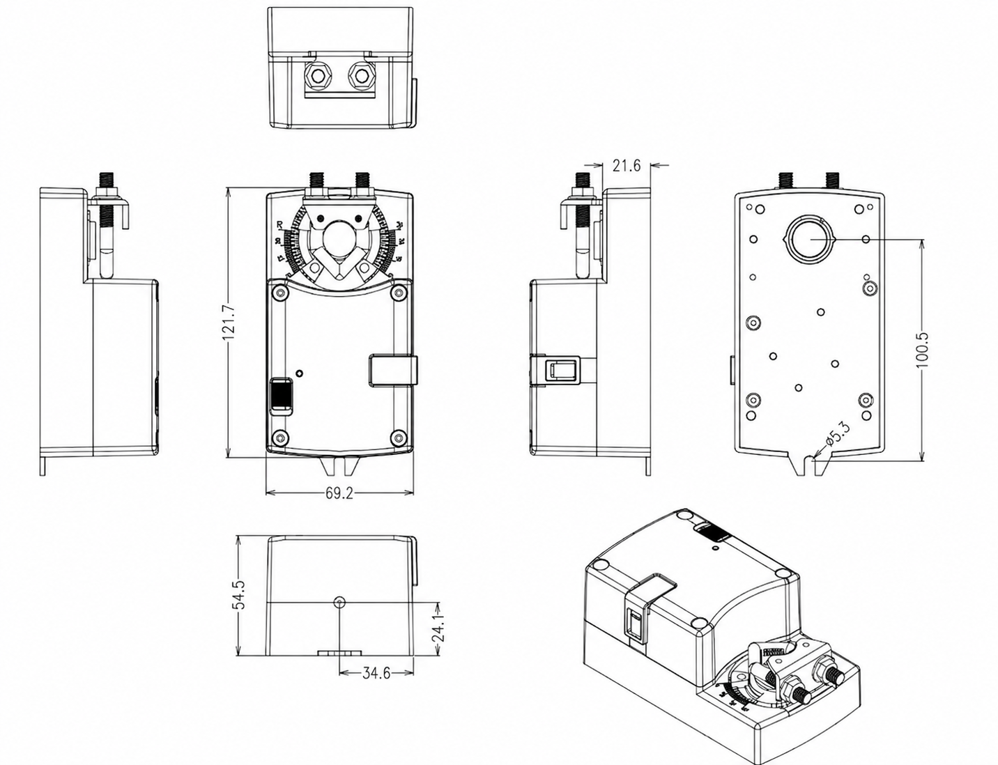
Torque and travel time are the first configuration decisions, but the actuator must also fit the shaft, enclosure space and panel power. The compact drawing below applies to the 5 Nm and 10 Nm family. Use it to check physical fit before comparing the compact and 30 Nm configurations in the table.
Configuration Comparison
The two enclosures share the same analog positioning task but serve different torque demands. Select the smallest configuration that remains above the damper’s actual torque with the project-required margin; do not estimate suitability from blade area alone.
| Specification | Compact Configuration | 30 Nm Configuration | Selection Check |
|---|---|---|---|
| Product type | Rotary direct-coupled analog actuator | Rotary direct-coupled analog actuator | For proportional blade positioning |
| Configuration family | RD/F-24-30/60/120 | RJ-24-60 | Use the supplied model on the final schedule |
| Rated torque | More than 5 Nm or 10 Nm | More than 30 Nm | Use actual breakaway and running torque |
| Rated runtime | 30, 60 or 120 seconds per 90 degrees | 60 seconds per 90 degrees | Match the control sequence |
| Rated supply | AC 24 V, 50/60 Hz or DC 24 V, +/-10% | AC 24 V, 50/60 Hz or DC 24 V, +/-10% | Check transformer and voltage drop |
| Power consumption | 7 W running; 0.5 W holding | 7 W running; 0.5 W holding | Size the panel for simultaneous loads |
| Control inputs | 0-10 V, 0-20 mA, 2-10 V, 4-20 mA or 0-10 kOhm, by configuration | Same available input families | Confirm one selected signal version |
| Position feedback | 0-10 V or 2-10 V, maximum 5 mA | 0-10 V or 2-10 V, maximum 5 mA | Match the receiving analog input |
| Positioning accuracy | Better than +/-1.0% | Better than +/-1.0% | Actuator position, not airflow accuracy |
| Rotation angle | Adjustable from approximately 30 to 95 degrees | Adjustable from approximately 30 to 95 degrees | Set mechanical limits to the damper travel |
| Rotation direction | CW or CCW by switch | CW or CCW by switch | Confirm command-to-blade direction |
| Shaft interface | 12-15 mm round or 10 x 10 mm square; minimum 40 mm projection | Same | Verify clamp engagement |
| Overall dimensions | 121.7 x 69.2 x 54.5 mm | 136.7 x 87.3 x 55.5 mm | Allow wiring and removal clearance |
| Connection | 80 cm cable, 5 x 0.75 mm2 | 80 cm cable, 5 x 0.75 mm2 | Confirm routing and termination |
| Operating environment | 0 to +50 C; 10-95% RH, non-condensing | Same | Indoor rating details beyond these values are not stated |
| Sound level | Maximum 52 dB | Maximum 52 dB | Test condition is not stated |
For the compact configurations, allow for the 121.7 x 69.2 x 54.5 mm enclosure plus cable, clamp and service clearance, and confirm a 12-15 mm round shaft or 10 x 10 mm square shaft with at least 40 mm projection. Keep the anti-rotation restraint and clamp accessible. The 30 Nm body measures 136.7 x 87.3 x 55.5 mm and requires its own enclosure clearance and model schedule.
How Torque and Runtime Change the Decision
Torque must cover the actual blade, seal, bearing and pressure load throughout travel, including the higher force that may be required to leave an end stop. Runtime determines how quickly the commanded position can change, but faster is not automatically better. A 30-, 60- or 120-second movement can be appropriate for normal AHU, terminal or duct modulation when the control loop is tuned to that response. When a critical-airflow or safety sequence requires a materially faster change, select the separate fast-response family instead of assuming the standard actuator will complete the same task.
Analog Control and Position Feedback
The analog damper actuator maps a proportional demand to a shaft position within the configured travel. A low demand moves the shaft toward one endpoint and a high demand moves it toward the other; the direction switch determines whether increasing demand produces clockwise or counterclockwise rotation. Mechanical limits define the usable angle, and the adaptation routine records those endpoints so the electrical demand is scaled across the installed movement.
Select One Compatible Signal Version
Available input families include 0-10 V, 2-10 V, 0-20 mA, 4-20 mA and 0-10 kOhm. These are configuration choices, not simultaneous universal inputs on every supplied unit. The controller output, actuator input and commissioning settings must use the same range. Voltage, current and resistance signals also require different panel and field-wiring checks, so the selected signal should be stated in the purchase schedule rather than decided after installation.
0-10 V Wiring Example
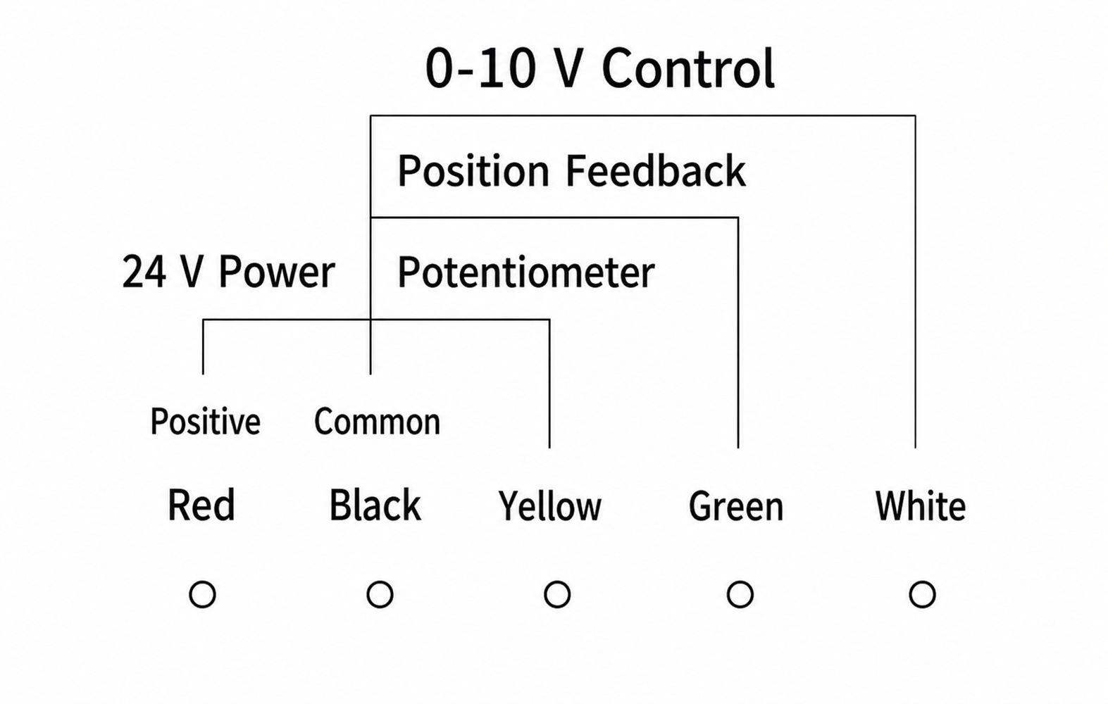
The diagram below shows the voltage-control arrangement. The actuator receives 24 V power, a 0-10 V positioning demand and a separate position-feedback output. Before assigning terminals, confirm the common reference shared by the controller and actuator, the feedback range accepted by the receiving input and the exact conductor schedule supplied with the selected version.
| Conductor | Circuit Function | Panel Check |
|---|---|---|
| Red | Positive AC/DC 24 V supply | Confirm source voltage, protection and transformer capacity |
| Black | Power and signal common / negative | Confirm the controller’s common-reference arrangement |
| White | 0-10 V position command in the illustrated version | Match output scaling and selected rotation direction |
| Green | Actuator-position feedback | Match 0-10 V or 2-10 V feedback to the receiving analog input |
| Yellow | Potentiometer/reference connection shown for the illustrated configuration | Terminate only as defined by the supplied model wiring sheet |
Use the figure and conductor table as one panel-design reference for the illustrated voltage-control version. Do not copy it unchanged to a current-input or resistance-input configuration; confirm the selected signal range, common-reference arrangement and feedback assignment on the supplied wiring sheet.
Position Feedback Is Not Airflow Feedback
The feedback signal reports the actuator’s mapped position. It can confirm that the drive moved toward the commanded angle, but it cannot confirm blade sealing, linkage integrity, actual air volume, duct pressure or the controlled condition at the terminal. When the control objective is airflow or pressure, use the appropriate sensor and controller to calculate the command, and verify the controlled variable independently during commissioning.
Direction, Angle and Adaptation
Set the mechanical limits to the damper’s safe travel before running adaptation. Then select the rotation direction so the controller’s minimum and maximum demands correspond to the intended blade positions. After adaptation, test intermediate commands as well as both endpoints. This check catches reversed direction, incorrect scaling and mechanical binding that an endpoint-only test can miss.
Direct-Coupled Mounting and Mechanical Fit
The actuator mounts directly on the damper shaft and uses an anti-rotation restraint to prevent the enclosure from turning with the clamp. A direct connection removes an external linkage, but it still requires correct shaft geometry, engagement length, actuator alignment and clearance. Mechanical fit should be confirmed from the damper drawing before torque and signal selections are released for manufacture.
Shaft Size and Projection
The documented clamp accepts a 12-15 mm round shaft or a 10 x 10 mm square shaft, with at least 40 mm of shaft projection. Measure the usable projection after allowing for bearings, collars and the damper frame. The clamp must engage the shaft fully without forcing the actuator against the bearing or leaving the anti-rotation restraint under side load.
Rotation Range and Mechanical Stops
The working angle can be limited from approximately 30 to 95 degrees. Set both limits to the blade’s safe mechanical range rather than assuming every damper uses a full 90-degree stroke. The end stops should prevent overtravel before the blade, seal or linkage reaches a damaging position, while preserving the movement needed for the specified minimum and maximum control states.
Enclosure and Service Clearance
The compact 5/10 Nm body and the larger 30 Nm body use different envelopes. Leave room for the cable bend, clamp fasteners, direction switch, adaptation control and removal path. Side-by-side dampers may require more spacing than the actuator width alone suggests, especially when access is available from only one side of the duct.
Torque Must Come from the Damper
Select torque from the damper manufacturer’s breakaway and running values at the expected pressure and seal condition. Blade area alone does not account for seals, bearings, contamination, pressure loading or shaft condition. If the torque data are unavailable, obtain or measure them before choosing between 5 Nm, 10 Nm and 30 Nm configurations.
Applications and Project Fit
This modulating damper actuator is intended for rotary air-control dampers that need stable intermediate positioning and can operate within a 30- to 120-second travel range. The application must provide a compatible 24 V power source and analog controller output, and the selected torque must be checked against the actual damper assembly.
Air-Handling and General Duct Modulation
In air-handling units, branch ducts, outside-air paths, return-air paths and ordinary ventilation zones, the actuator can position a compatible blade in response to temperature, pressure, airflow or supervisory demand from a separate controller. The controlling variable depends on the system sensor and sequence; the actuator itself receives only the position command and returns shaft-position feedback.
VAV Terminals and HVAC Branch Control
The family can be used on compatible VAV terminal, supply, return and exhaust dampers when the required torque, signal and response time fall within the selected configuration. Temperature, airflow or duct-pressure demand must come from the corresponding HVAC sensor and controller. Contaminated exhaust service also needs a separate compatibility review for exposed components and installation conditions; the actuator designation does not establish corrosion resistance.
Applications Requiring a Different Family
Do not use this family as a substitute for a certified fire or smoke actuator, a spring-return fail-safe actuator, an explosion-protected device or an outdoor-rated enclosure. A networked control requirement belongs with a communicating actuator, and a response faster than 30 seconds belongs with the fast-modulating family. Linear linkage travel requires a linear-stroke actuator rather than this rotary direct-coupled construction.
Conditions That Need Project Confirmation
- Damper torque at the actual pressure, seal and contamination condition
- Indoor environmental conditions beyond the stated temperature and humidity range
- Power-loss position and any safety interlock outside normal proportional control
- Signal isolation, common references and cable routing in the control panel
- Required documents, local compliance and acceptance tests for the destination project
How to Select and Specify the Actuator
A usable actuator schedule starts with the damper load and operating sequence, then resolves mechanical fit, electrical compatibility and commissioning behavior. Selecting only by the phrase “0-10 V actuator” leaves the most important mechanical and safety decisions undefined.
1. Establish Required Torque
Obtain breakaway and running torque from the damper manufacturer for the installed blade, seals, bearings and pressure condition. Apply the project-required margin and choose the 5 Nm, 10 Nm or 30 Nm configuration that satisfies that load. Record the source and condition of the torque value in the equipment schedule.
2. Select the Required Travel Time
Choose 30, 60 or 120 seconds per 90 degrees according to the control loop and operating sequence. Normal comfort, process or ventilation modulation may favor a stable standard-speed movement. Emergency exhaust, rapid containment or another fast sequence should be evaluated against the separate fast-modulating range rather than handled by tuning alone.
3. Confirm Shaft and Installation Geometry
State the shaft as round or square, provide its dimensions and usable projection, and confirm whether the compact or 30 Nm enclosure fits the available space. Include mounting orientation, nearby ductwork and service-access constraints when they affect clamp or cable access.
4. Match Command and Feedback Signals
Select one command range that the controller can drive and one position-feedback range that the receiving input can read. Identify the common-reference arrangement and whether isolation is required. Do not use actuator-position feedback as the acceptance signal for airflow or pressure control.
5. Define Normal and Loss-of-Power Behavior
Document which blade position corresponds to minimum and maximum demand, the required rotation direction and the safe response to power loss. This family has no documented automatic spring-return action. If a defined mechanical return position is mandatory, select the spring-return product family or provide another approved system-level solution.
Information Needed to Configure the Product
- Application, damper type, dimensions, blade and seal construction
- Breakaway torque, running torque and operating pressure condition
- Required runtime, working angle and normal rotation direction
- Shaft form, size, usable projection and available installation clearance
- AC/DC 24 V source, transformer capacity and cable requirements
- Command signal, position-feedback signal and controller I/O details
- Power-loss sequence, interlocks and independent airflow or pressure sensors
- Quantity, destination and required drawings or submittals
Installation and Commissioning
Installation must establish a mechanically free stroke before electrical adaptation is performed. Commissioning then confirms that the controller demand, actuator direction, mapped angle and feedback signal agree across the complete operating range.
Mechanical Installation
- Isolate the damper and verify that the blade can travel through the intended range without binding.
- Set the blade and actuator to known corresponding positions before tightening the shaft clamp.
- Engage the shaft fully and secure the anti-rotation restraint without distorting the enclosure.
- Set the mechanical limits within the damper’s safe travel and confirm service clearance.
- Check that the cable is supported and clear of moving parts, sharp edges and hot surfaces.
Electrical Connection
Verify the selected signal version before terminating conductors. Check 24 V source capacity and polarity where applicable, confirm the controller and actuator common-reference arrangement, and connect command and feedback only to compatible analog I/O. Use the supplied model wiring sheet rather than relying on conductor color alone, particularly when the input is current or resistance instead of the illustrated 0-10 V version.
Adaptation and Functional Test
After mechanical limits are set, run the adaptation function to map the installed endpoints. Apply minimum, midpoint and maximum demands and verify the actual shaft movement, displayed position feedback and commanded direction. Confirm that the damper does not bind at either limit and that intermediate movement is repeatable. For an airflow- or pressure-controlled branch, complete a separate functional test using the system sensor and balancing method.
Commissioning Records
Record the supplied configuration, torque, runtime, signal ranges, rotation direction, mechanical angle, endpoint settings and measured feedback at the test commands. Also record any controller scaling, independent airflow or pressure readings and the observed response to power removal. These values provide a useful baseline for later service without implying performance that was not tested.
Frequently Asked Questions
What is a modulating damper actuator?
A modulating damper actuator moves an damper shaft to intermediate positions in response to a proportional control signal. This family uses 24 V power and direct rotary coupling, with analog command and actuator-position feedback selected for the control panel.
Which torque options are available?
The compact family provides configurations rated above 5 Nm or 10 Nm. A larger body provides more than 30 Nm. Select torque from the damper’s breakaway and running load at the actual pressure and seal condition, not from blade area alone.
Does every unit accept 0-10 V, 4-20 mA and resistance inputs?
No. A 0-10 V damper actuator, current-input configuration and resistance-input configuration belong to available signal families, but the supplied unit must be ordered for the signal used by the controller. Its wiring must follow the matching diagram.
What does the feedback signal measure?
It reports the actuator’s mapped shaft position. It does not measure airflow, pressure or face velocity and cannot confirm damper leakage or blade sealing. Those variables require separate sensors and acceptance tests.
Is this a spring-return or fail-safe actuator?
No automatic spring-return action is documented for this family. If the damper must move mechanically to a defined position when power is removed, specify the spring-return actuator family and confirm the required return direction and torque.
Can this actuator communicate directly with a BMS?
No network protocol is specified for this family. The actuator can provide an analog position signal to a compatible controller or BMS input. Use the communicating actuator family when an approved RS-485 interface is required.
How much shaft projection is needed?
The documented minimum projection is 40 mm. The shaft must also match the 12-15 mm round or 10 x 10 mm square interface and leave enough usable length after bearings, collars and the damper frame are considered.
How is the travel commissioned?
Set the mechanical limits to the damper’s safe angle, select the required rotation direction and run the adaptation function. Then apply minimum, midpoint and maximum commands while checking actual movement and position feedback.
What information is required for a quotation?
Provide damper type and dimensions, torque, runtime, shaft geometry, installation clearance, 24 V supply, command and feedback signals, working angle, rotation direction, power-loss sequence, quantity, destination and required drawings.
Contact the Xicheng Engineering Team Today.
Send the damper schedule, breakaway and running torque, required runtime, shaft dimensions, available mounting space, AC/DC 24 V source, command and feedback ranges, normal rotation direction, working angle, power-loss sequence, quantity and destination. XICHENG will return a proposed modulating damper actuator configuration, applicable dimensions and electrical data, mounting and wiring information, required confirmation items and commercial pricing.
🎯 Shenzhen Office: No. 34 Zhenxing Road (Shengtaian Heavy Industrial Park B), Loucun, Guangming New Dist, Shenzhen, Guangdong, China
☎️ WhatsApp: +86 181 2647 8161
📬 Engineering Mailbox: fanalax34@gmail.com