


Description
Automatic Fume Hood Sash Controller Overview
What the Controller Does
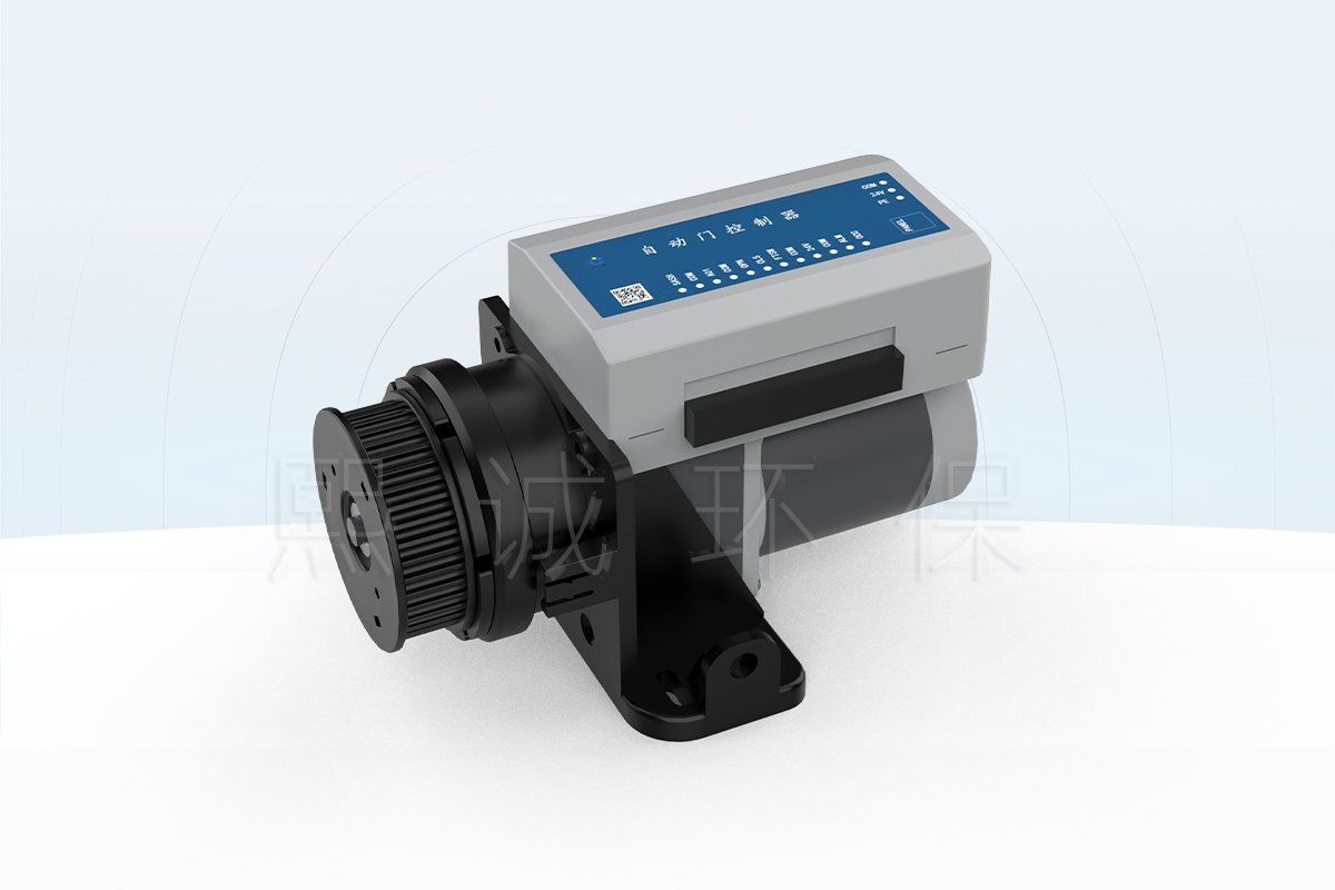
An automatic fume hood sash controller moves a vertical sash in response to position feedback and selected operating inputs. The FSC10 controller combines the control logic, motor drive and local-panel connection in one field device. It can read either a potentiometer-style or electromagnetic displacement sensor, accept manual open and close commands, and respond to occupancy, foot-switch and anti-pinch inputs. The controller then drives the sash mechanism according to the configured manual, follow or energy-saving mode.
The controller is designed for a complete moving-sash assembly rather than an isolated electrical panel. The sash, counterbalance, motor, pulley or belt transmission, position sensor and protective inputs must work as one mechanical and control system. These items are selected around the actual hood geometry and operating sequence, so the product name alone is not enough to establish retrofit compatibility or the supplied component package.
Choose This Controller When
This fume hood auto-sash controller is a practical choice when the project needs repeatable powered movement of a vertical sash and can define the mechanical travel, position feedback and safety inputs before ordering. It is particularly relevant for laboratory projects that want the sash to respond to occupancy or local commands while preserving a manual operating path through the controller’s clutch-supported changeover.
- The hood has a vertically moving sash whose travel and counterbalance can be checked for powered operation.
- The control sequence requires manual, follow or energy-saving operation rather than only a conventional hand-operated sash.
- A potentiometer or electromagnetic displacement sensor can be installed to represent the actual sash position.
- The design needs separate inputs for manual open/close, occupancy, anti-pinch protection and a foot switch.
- The installation can be commissioned for travel limits, sensor scaling, movement time and obstruction response.
Information Needed to Configure the System
Start with the fume hood and sash rather than the controller model. Provide the hood drawing, clear sash opening, total travel, sash weight and counterbalance arrangement, drive and pulley layout, available installation space, desired movement time, position-sensor preference, operating modes, occupancy and anti-pinch devices, foot-switch requirement, power location and quantity. The control sequence should also state what the sash must do when an occupant approaches or leaves, when the anti-pinch input operates, and when local manual control is used. These details allow the controller, motor, sensor and transmission package to be matched without assuming that every component in the system illustration is included by default.
Key Specifications and Controller Interfaces
The specification table brings the electrical, environmental, position and control interfaces together before the operating detail. Values shown here are documented for the FSC10 controller. The selected sensor, movement time, output convention and companion components must still be identified in the order and approved wiring schedule.
| Specification | FSC10 Controller Data |
|---|---|
| Product type | Automatic controller for a vertical fume hood sash |
| Power supply | 24 VDC, +/-10% |
| Maximum power | 20 W max |
| Operating environment | 0 to +50 degrees C; 10-95% RH, non-condensing |
| Storage environment | -20 to +50 degrees C; 10-95% RH, non-condensing |
| Position-sensor input | One potentiometer input supporting 2 kOhm, 3 kOhm or 10 kOhm sensors, plus one electromagnetic displacement-sensor interface |
| Sash-opening output | One voltage analog output representing actual sash opening; confirm the ordered 0-10 V or 2-10 V convention on the approved wiring schedule |
| Dry-contact inputs | Five inputs: manual open, manual close, anti-pinch, occupancy and foot switch |
| Motor control | Integrated motor driver |
| Operating modes | Manual, follow and energy-saving |
| Travel-time setting | Configurable; 2-6 seconds shown in the controller setting data |
| Panel interface | Dedicated RJ12 communication port |
| Manual/electric changeover | Integrated clutch |
Electrical and Environmental Data
The controller uses a 24 VDC supply and has a published maximum power of 20 W. The power source and cable sizing must also account for the connected drive arrangement and the project’s distribution design; the controller specification does not establish a universal branch-circuit layout. The documented operating range is 0 to +50 degrees C at 10-95% relative humidity without condensation. Installation inside a wet, condensing or chemically exposed zone requires a separate enclosure and compatibility review because no ingress-protection claim is established for the controller itself.
The storage range extends from -20 to +50 degrees C at the same non-condensing humidity condition. This is a storage limit, not permission to energize or operate the controller below its operating temperature. Keep the control unit and connectors accessible for setup and service, and protect wiring from the moving sash, belt or pulley path.
Sash Position, Inputs and Outputs
Position feedback can come from a resistive potentiometer or an electromagnetic displacement sensor. The two sensor interfaces are alternatives selected around the mechanical layout and calibration method; they are not two position readings that must be used together. The potentiometer input supports 2 kOhm, 3 kOhm and 10 kOhm devices. The electromagnetic interface uses a configurable travel-per-revolution value so the controller can relate sensor movement to sash travel.
Five dry-contact inputs separate the operating commands and protective functions. Manual open and close inputs provide local movement commands. The occupancy input supports an occupancy-dependent sequence, the foot-switch input provides a separate field command, and the anti-pinch input is used by the protective response. These contacts do not supply a complete site sequence on their own; the intended contact states and sash actions must be documented during configuration.
The controller provides an analog signal representing the actual sash opening. XICHENG’s product text identifies a 0-10 V output, while the source wiring drawing labels 2-10 V. This difference is treated as an available signal convention that must be fixed in the quotation and approved wiring schedule. The page does not assume that both ranges apply to every unit.
Controller Dimensions and Installation Envelope
The drawing shows a 213.00 mm overall controller-and-bracket height, 176.00 mm width and 107.60 mm depth. It also identifies the 5M40 belt pulley and mounting details around the drive assembly. These dimensions describe the illustrated FSC10 arrangement; the surrounding clearance must also accommodate the moving transmission, cable bends, mounting fasteners and access to the clutch and panel connection.
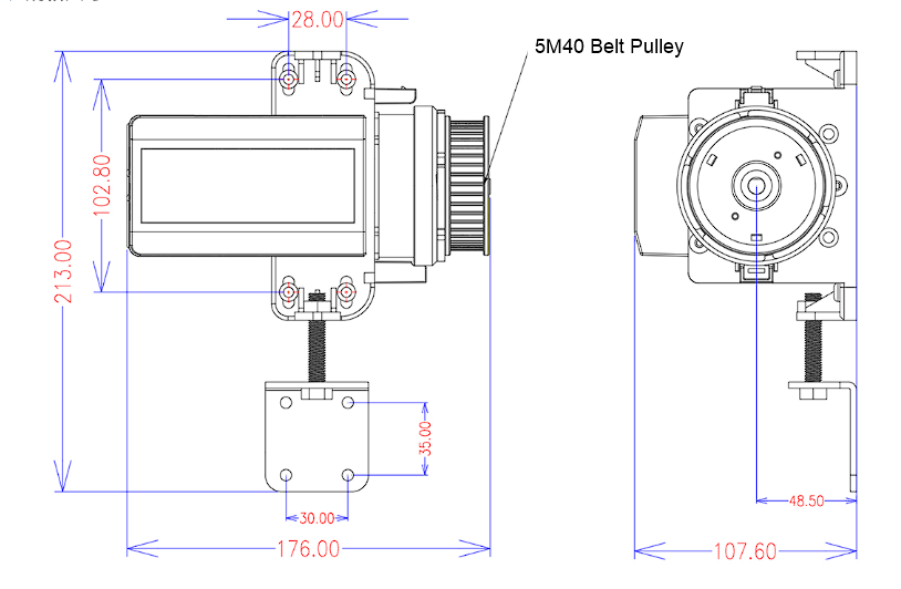
Before the mounting plate is released, compare the drawing with the hood sidewall, sash counterbalance, belt path and service access. The 213 mm overall height and 176 mm width do not define the complete moving envelope. A retrofit also needs confirmation that the existing sash moves freely and that the selected attachment points do not introduce side load, overtravel or interference.
Operating Modes and Sash Movement Logic
The automatic sash controller separates direct local movement from sensor-dependent operation. Manual, follow and energy-saving modes are available, but the final sash actions depend on the configured inputs and the approved project sequence. This matters because the same controller may be applied to different sash travels, sensor types and occupancy requirements without making one universal movement sequence appropriate for every hood.
Manual Mode
Manual open and close commands are provided through separate dry-contact inputs. The local panel also has up and down keys: the sash moves while a key is pressed and stops when the key is released. This mode is useful for setup, routine local positioning and controlled service checks. It does not remove the need to verify the anti-pinch input, travel limits and mechanical clearance before movement.
The integrated clutch supports manual/electric changeover at the drive. Manual operation is therefore a mechanical operating path, not a promise that every connected function remains active without electrical power. The procedure for disengaging the drive and the acceptable manual force must be confirmed for the supplied motor and transmission assembly.
Follow Mode
Follow mode allows the automatic fume hood sash controller to act on the configured sensor and command relationship rather than relying only on a continuous button press. The controller can track sash position from the selected displacement sensor and use the defined occupancy, anti-pinch, foot-switch or manual inputs when deciding whether movement is permitted. A short press of the panel’s disable key can inhibit the follow function when automatic movement is not wanted.
The mode name does not by itself define an opening distance, delay or final position. Those actions are established through the project’s selected settings and control sequence. The position sensor must first be scaled to the real sash travel so that an apparent controller position corresponds to the physical sash.
Energy-Saving Mode
Energy-saving mode is intended for projects that reduce the open sash area when the hood is not being actively used. Closing or lowering the sash can reduce the airflow demand only when the associated exhaust-control system has been designed to respond to sash position or another verified control variable. FSC10 performs the sash movement; it does not calculate the exhaust airflow or guarantee a fixed energy-saving percentage.
The occupancy leave delay and the selected occupancy action determine how the sash-control sequence responds after the detection state changes. Available occupancy actions include stop, open and return to the previous position. The project sequence must select the action that is appropriate for the hood, work process and ventilation strategy rather than treating one menu choice as a universal default.
Local Panel and Adjustable Settings
The dedicated RJ12 panel provides up, disable and down keys. Its green indicator identifies normal operation, yellow identifies parameter-setting mode, red identifies a disabled follow function, and an unlit state identifies a panel communication fault. Holding the disable key enters or exits the setting mode, while a short press changes the follow-function state.
Adjustable fields include the occupancy leave delay, occupancy action, anti-pinch action, fully closed offset, maximum-current offset, sash travel time, position-sensor scaling, total sash travel and automatic setup command. The published travel-time setting is 2-6 seconds. Sensor scaling is entered differently for the electromagnetic and potentiometer arrangements, so the installed sensor type must be identified before automatic travel setup. These settings should be recorded with the commissioned hood rather than left as undocumented field changes.
Safety Inputs, Position Feedback and Wiring
The controller’s protective and operating inputs have different jobs. The anti-pinch sensor and current limit respond to obstruction-related conditions, while occupancy, foot-switch and manual contacts request normal sash actions. Position feedback tells the controller where the sash is. Keeping these signal roles separate is essential when the wiring schedule and acceptance tests are prepared.
Anti-Pinch and Current-Limit Protection
The infrared anti-pinch input provides one layer of obstruction protection. Its configured response can stop or open the sash when the alarm input operates. The sensor must be positioned so that its protected area covers the relevant closing path without being blocked by the hood structure, stored items or the moving transmission.
Full-travel current limiting provides a second layer by monitoring the drive load during movement. It is not interchangeable with the infrared input: a current rise is a mechanical/load condition, while the infrared device is a separate detection input. Both functions must be tested on the assembled hood. Neither statement is a safety certification or a guarantee that every object, hand position or mechanical fault will be detected.
Occupancy, Foot-Switch and Manual Inputs
The occupancy input allows the movement sequence to respond after an occupant approaches or leaves the hood. The controller provides a leave-delay setting and configurable actions, including stop, open or return to the previous position. The selected action must match the laboratory’s operating procedure; occupancy detection should not be treated as confirmation that the work area is clear of equipment or experiments.
A foot switch can provide a separate hands-free request through a relay contact. Manual open and close contacts remain distinct inputs, allowing wall switches or another approved dry-contact device to command movement. These are command contacts, not powered analog inputs. Contact type, normal state, cable routing and the priority between simultaneous inputs belong on the project wiring and sequence documents.
Position Feedback and Analog Output
The selected sash-position sensor feeds the controller’s SASH/COM interface or the dedicated electromagnetic sensor connection. That signal is scaled against the physical travel during setup. The controller then uses the position to manage movement and can provide an analog output representing the actual sash opening for a compatible external system.
The product specification identifies this output as 0-10 V, while the FSC10 wiring drawing labels it 2-10 V. The required signal convention must therefore be stated in the order and confirmed on the approved wiring diagram. A controls contractor should not infer the range from the page title or reuse a setting from another hood.
Wiring and Interface Boundaries
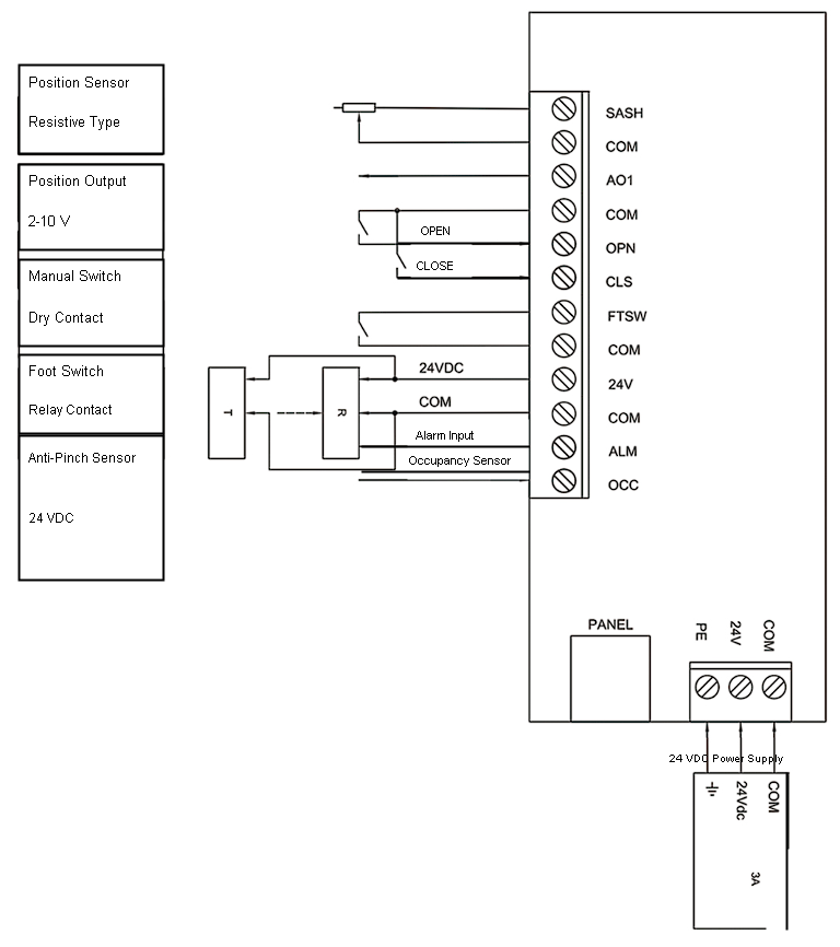
| Interface | Visible Terminal / Signal | Project Check |
|---|---|---|
| Position sensor | SASH, COM | Confirm resistive sensor value or the selected electromagnetic sensor arrangement and scaling. |
| Position output | AO1, COM | Confirm the ordered voltage range and receiving-device input. |
| Manual commands | OPN, CLS and COM | Use approved dry contacts and define command priority. |
| Foot switch | FTSW, COM | Confirm relay-contact state and local operating procedure. |
| Anti-pinch sensor | 24V, COM, ALM | Confirm sensor power, alarm state, detection area and configured stop/open action. |
| Occupancy sensor | OCC with the shown sensor supply/common arrangement | Confirm detection coverage, leave delay and selected occupancy action. |
| Local panel | PANEL | Use the dedicated RJ12 panel connection and verify communication indication. |
| Controller supply | PE, 24V, COM | Provide the approved 24 VDC supply and protective-earth arrangement shown for the installation. |
The documented communication connection is the dedicated panel port. No Modbus, BACnet or general BMS protocol is established for this sash controller, so those capabilities are not part of the product specification. If the project needs supervisory integration, use the confirmed position output and dry-contact functions or select a separately documented interface device.
Automatic Sash System Components and Mechanical Fit
An automatic sash controller cannot move a fume hood window without a matched mechanical and sensing package. The FSC10 system relationship includes the controller, local panel, position sensor, anti-pinch sensor, occupancy detector, drive motor, synchronous pulley and timing belt. The quotation must state which of these components are supplied because the system illustration does not define one universal standard package.
Core Controller and Companion Components
The controller supplies the movement logic, motor drive, dry-contact inputs, position processing and local-panel connection. A compatible automatic fume hood sash motor converts the command into movement. The automatic sash drive pulley and belt transfer that motion to the sash mechanism, while the position sensor closes the movement-position relationship used during setup.
The fume hood occupancy sensor and infrared sash safety sensor perform different tasks. Occupancy detection informs an operating sequence after presence changes. The anti-pinch sensor monitors the closing path for an obstruction condition. Neither device measures sash position, and neither should be substituted for the other in the wiring or acceptance plan.
Position-Sensor and Drive Selection
A string potentiometer for fume hood sash position is useful when a protected linear draw-wire path can follow the full sash travel. A rotary position sensor is selected when the pulley or shaft arrangement provides a reliable rotational relationship to sash position. The choice depends on available space, travel length, cable or shaft alignment, transmission ratio and calibration method rather than on the sensor name alone.
The motor and transmission must be selected from the real moving load. Record sash weight, counterbalance condition, friction through the full travel, pulley geometry, belt path, attachment points and desired movement time. A sash that binds when moved by hand should be corrected mechanically before a powered operator is installed. Increasing drive force is not an appropriate substitute for a free-moving, correctly balanced sash.
Standard Scope Versus Project Options
| Component Group | Function | Selection / Supply Check |
|---|---|---|
| FSC10 controller | Movement logic, motor drive, position processing and input handling | Core controller; confirm the ordered signal configuration and firmware/settings record. |
| Control panel | Local movement, mode disable, indication and parameter access | Confirm panel type, cable, mounting location and inclusion. |
| Position sensor | Represents actual sash travel | Select potentiometer or electromagnetic/rotary arrangement and confirm scaling. |
| Motor and transmission | Moves the sash through the pulley/belt mechanism | Confirm load, counterbalance, travel, movement time, pulley bore and attachment geometry. |
| Occupancy and anti-pinch sensors | Provide presence and obstruction-related inputs | Confirm detector type, coverage, mounting, wiring and configured action. |
| Foot and manual switches | Provide local dry-contact commands | Confirm contact state, operator location and command priority. |
For a project-ready quotation, request a component schedule rather than assuming that every companion part is included. The schedule should identify the controller, selected sensor, motor, pulley and belt, panel, protective sensors, switches, cables, power supply, mounting parts and available drawings. Any component supplied by the hood manufacturer or site contractor should be shown as an interface responsibility.
System Integration and Product Selection
Use with CAV or VAV Fume Hoods
The automatic fume hood sash controller can be applied to a hood with constant- or variable-air-volume ventilation because its primary task is mechanical sash movement. In a CAV hood, automatic closing may reduce the unattended open area and improve the operating discipline around the sash, but it does not change a fixed exhaust setpoint by itself. The effect on room air balance and exhaust energy depends on the actual ventilation design.
In a VAV hood, the analog sash-opening signal may be used as one input to a separately engineered airflow sequence. The controls designer must define the signal range, receiving controller, sash-to-airflow relationship, minimum and emergency airflow, response to sensor faults and final commissioning method. Actual face velocity or exhaust performance must be measured by the equipment assigned to that task; sash position alone cannot verify containment.
Sash Control Versus Airflow Control
Sash control answers a movement question: where should the sash move in response to local commands, presence and protective inputs? Airflow control answers a ventilation question: what exhaust airflow is required to maintain the specified hood condition as the opening and system pressure change? These functions can exchange a position signal, but they remain separate control responsibilities.
Select FSC10 when powered sash movement, position tracking and sash-related safety inputs are the required functions. Select or retain a separate airflow or face-velocity control system when the project also needs measurement, damper or valve modulation, fan coordination, airflow alarms or building-controls communication. The product page does not assign those airflow functions to the sash controller.
Application and Retrofit Conditions
Good applications include new vertical-sash fume hoods designed around an automatic drive, and existing hoods whose sash, counterbalance and frame can be verified for powered movement. A retrofit assessment should confirm smooth manual travel, available mounting space, a safe transmission path, protected sensor routing, suitable attachment points and access for service. The system also needs a defined method for local operation when automatic movement is disabled.
Do not select the controller for a horizontal-only sash, a binding or unbalanced window, or a project that cannot provide a position sensor and commissioning access. It is also not a substitute for a certified fire or smoke closure, a machine-guarding safety controller, or a complete fume hood ventilation system. Where the work process requires the sash to remain at a fixed opening, the operating sequence must prevent an occupancy or energy-saving command from moving it unexpectedly.
Configuration Decisions That Affect the Order
The order should identify the sensor architecture, sash travel, motor and pulley arrangement, desired movement time, manual controls, occupancy behavior, anti-pinch behavior, foot-switch use, panel location and analog output convention. For multi-hood projects, prepare a tag-by-tag schedule because sash dimensions, counterbalance condition and field interfaces may differ even when the same controller model is used.
XICHENG can use the hood drawings and control sequence to define a proposed component package and interface schedule. The quotation should list the supplied controller, panel, sensor, motor, transmission and protective devices; it should also identify items provided by the hood manufacturer, controls contractor or site installer. This division of scope is more useful than treating the automatic sash system as a single unspecified accessory.
Installation, Setup and Commissioning
Commissioning starts with the sash mechanism, not with a software setting. The window must move freely through its complete travel, the counterbalance must be stable, and the motor, pulley, belt and sensor must remain aligned at both endpoints. Electrical setup should begin only after the mechanical path and protective detection area have been checked.
Mechanical Checks Before Power-Up
Move the sash manually and inspect for binding, frame contact, damaged guides or counterweight interference. Confirm that the drive attachment cannot overtravel and that the belt or cable remains engaged throughout the full movement. The motor and controller need service clearance, while sensor and panel cables need a protected route outside the moving transmission.
Check the anti-pinch sensor’s detection area with the sash at several positions. The occupancy detector should cover the intended operator zone without being aimed at unrelated traffic. A foot switch or manual switch must be positioned where the operator can see the sash path before issuing a command. Correct mechanical or coverage problems before applying power rather than compensating for them with higher current or a longer delay.
Sash Travel and Sensor Setup
Identify the installed position-sensor type before calibration. An electromagnetic arrangement requires its travel-per-revolution value; a potentiometer arrangement requires the corresponding resistance-per-travel value. The controller also records the total sash travel through its automatic setup process. Incorrect sensor selection or scaling can produce a position value that looks stable but does not represent the physical sash opening.
The setup process begins with the sash near, but not at, the fully closed position and the local panel placed in setting mode. After the correct sensor scaling has been entered, automatic travel setup is started and the sash is moved through the required learning sequence. The controller data indicates a 50 cm stopping position after a successful setup. If that physical position is not correct, the mechanical travel and sensor scaling should be checked before the process is repeated.
Then configure the fully closed offset, movement time, occupancy leave delay, occupancy action, anti-pinch action and maximum-current offset for the actual hood. These values should be recorded in the commissioning sheet. They are operating settings for one sash assembly, not universal values to copy across different hood sizes or retrofit conditions.
Control Panel Installation
The panel mounting drawing identifies two D5.0 fixing holes and a D26 cable opening. It also shows the reference hole spacing and overall mounting pattern needed to prepare the panel location. Install the panel where the operator can see the sash, reach the up/down/disable keys and observe the status indicators without entering the sash path.
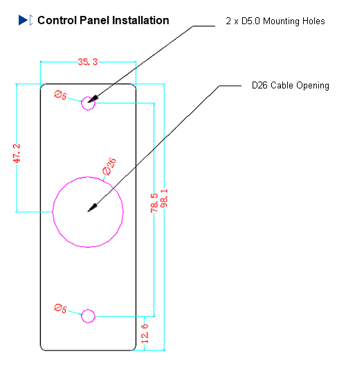
Keep the RJ12 cable away from the motor transmission and sharp edges, and leave enough slack for service without allowing the cable to enter the moving area. Verify the panel indication after connection: normal operation, parameter-setting mode, disabled follow function and communication fault each have a distinct indicator state.
Functional Acceptance and Service Checks
Acceptance testing should exercise every installed input and movement path. Verify local up and down operation, external manual contacts, occupancy response and leave delay, foot-switch command, anti-pinch response, current-limit response, full travel, closed-position offset, analog position output and panel communication. Test the selected movement time with the real sash load and confirm that the mechanism does not bind or overrun at either endpoint.
Document the configured sensor type, scaling, total travel, signal range, input actions and supplied components. Power-failure position, restart behavior, external interlocks and fault reset are not universal FSC10 values and must be agreed for the project. During service, begin with mechanical freedom, sensor alignment, belt engagement, wiring and panel indication before changing configuration. This order helps distinguish a physical sash problem from a control-setting problem.
Frequently Asked Questions
Is this an airflow or face-velocity controller?
No. The product controls the movement and position of a vertical fume hood sash. It can provide an analog signal representing the sash opening, but it does not measure face velocity, modulate an exhaust damper or verify containment. Those duties require a separately specified airflow-control system when the hood uses CAV or VAV ventilation.
Can it be fitted to an existing vertical-sash fume hood?
A retrofit is possible when the existing sash moves freely, remains correctly counterbalanced and provides suitable space for the motor, controller, transmission, sensor and protected wiring. Compatibility cannot be decided from the hood width alone. The sash travel, weight, guide condition, pulley path, attachment points and service clearance should be reviewed from drawings and site measurements.
Which sash-position sensor should be selected?
Use a string-potentiometer arrangement when a protected linear draw-wire path can follow the full sash travel. Use the electromagnetic or rotary arrangement when the pulley or shaft provides a reliable rotational relationship to sash position. Selection depends on travel, mounting path, transmission ratio and calibration method. The selected sensor type and scaling must be recorded during setup.
How do anti-pinch detection and current limiting work together?
The infrared anti-pinch sensor provides a separate alarm input for the closing path. Current limiting monitors the drive load during movement. They address different obstruction conditions and should both be tested on the assembled hood. Neither function should be described as an absolute safety guarantee, and the configured stop or opening response must match the project’s operating procedure.
Can the sash still be moved manually?
Yes. The controller has an integrated clutch for manual/electric changeover, and the local panel provides press-and-hold up and down operation when powered. The delivered mechanism should include a clear manual-changeover procedure, and manual force should be checked with the actual sash and counterbalance.
How does the controller work with a VAV fume hood?
The controller can send the actual sash-opening signal to a compatible ventilation control design. That separate system determines the required airflow from its approved sequence and verifies actual hood performance with the required sensing and commissioning method. Confirm the analog range, receiving input, minimum and emergency airflow behavior, and response to signal faults before connecting the two systems.
What information is required for a quotation?
Provide the fume hood drawing, sash type, clear opening, total travel, sash weight and counterbalance arrangement, motor and pulley layout, desired movement time, selected position sensor, occupancy and anti-pinch requirements, foot or manual switches, operating sequence, analog output requirement, panel location, available 24 VDC power, quantity and installation destination. Mark any components that will be supplied by the hood manufacturer or controls contractor.
Contact the Xicheng Engineering Team Today
Send the hood and sash drawings, travel and load information, proposed drive arrangement, position-sensor choice, required movement sequence and safety-input plan. XICHENG will review the mechanical and control interfaces and prepare a product configuration, component scope and quotation for the automatic fume hood sash system.
Shenzhen Office: No. 34 Zhenxing Road (Shengtaian Heavy Industrial Park B), Loucun, Guangming New Dist, Shenzhen, Guangdong, China
WhatsApp: +86 18126478161
Engineering Mailbox: fanalax34@gmail.com