


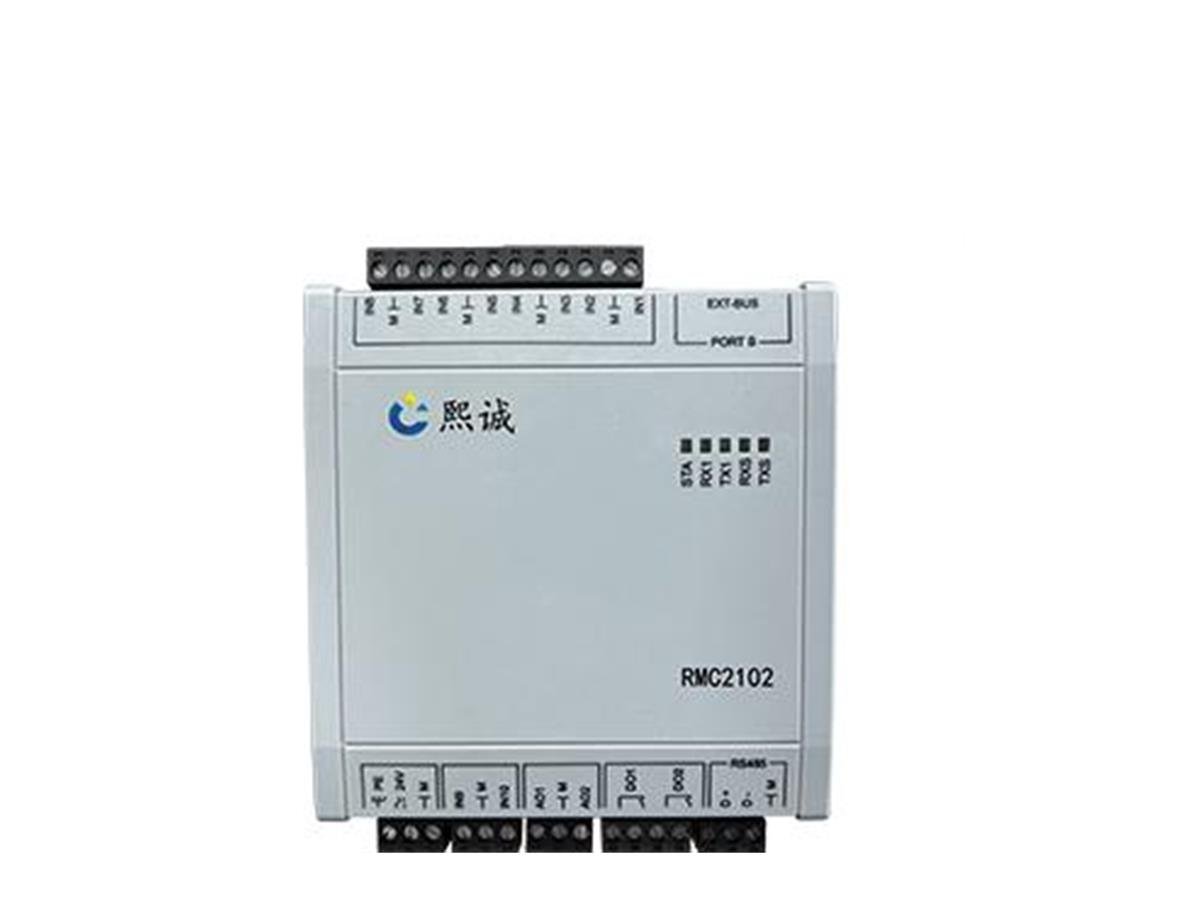
Description
Laboratory Room Controller Overview
RMC2102 is a laboratory room controller for projects that must coordinate changing supply and exhaust airflow while supervising the resulting pressure relationship. It can monitor the configured combination of temperature, humidity, room pressure gradient, and supply/exhaust fan status, then command the selected airflow-control devices according to a residual-airflow or differential-pressure cascade sequence.
This controller is most useful when room demand changes because of fume hoods, equipment exhaust, operating modes, or process ventilation. Instead of treating supply, general exhaust, and local exhaust as unrelated branches, the control sequence accounts for the air streams that affect the room balance and assigns a lead/follower relationship. The selected sensors, air dampers or valves, actuators, fan system, available pressure, room leakage, and commissioning determine the final result.
Each controller is scheduled against a named room or control zone so its measurements, outputs, modes, and alarms remain traceable from design through commissioning.
Choose This Controller When
- Fume hood or equipment-exhaust demand changes and another room airflow branch must track it.
- The room uses a defined supply-to-exhaust offset to support a positive or negative pressure relationship.
- Differential pressure must supervise or trim an airflow-tracking sequence.
- Supply and exhaust fan operating status is part of the room-control logic.
- The controller must exchange the required operating and monitoring points with a BMS through RS-485 Modbus RTU.
Key Information to Provide First
Provide every supply, general-exhaust, fume hood, and equipment-exhaust airflow state that affects the room. Mark each value as measured, commanded, fixed, or unavailable. Define the required room pressure direction, airflow offset, operating modes, door behavior, fan states, alarms, and emergency sequence. Then identify the measurement devices, controlled air dampers or valves, actuator signals, power, local display, communication points, and commissioning criteria.
Also identify which airflow branch leads during each operating mode and which branch has enough control range to follow it.
Controller Scope Versus Complete Room System
RMC2102 supplies the configured room-control logic and communication path. A complete installation can also require airflow sensors, a differential-pressure sensor, supply and exhaust airflow-control devices, actuators, a room display, power supplies, wiring, network integration, fan interlocks, test and balance, and field acceptance. Included equipment follows the ordered scope.
Functions and Configuration Fields
RMC2102 is configured for the actual room-control architecture. The room schedule defines the electrical interface, I/O, sensors, airflow devices, operating sequence, and performance requirements for each controller.
Controller Function Matrix
| Selection Field | RMC2102 Function | Information to Specify |
|---|---|---|
| Product type | Laboratory room field controller | Room or zone tag and control objective |
| Primary control role | Supply and exhaust airflow coordination for room pressure-gradient control | Lead/follower branches and mode sequence |
| Control methods | Residual-airflow control and differential-pressure cascade control | Offset, pressure target, loop priority, trim limits, and timing |
| Monitoring scope | Configured temperature, humidity, pressure gradient, and supply/exhaust fan status | Sensor types, ranges, signals, locations, and alarm use |
| Controlled outputs | Commands selected supply and exhaust airflow-control devices | Device size, range, actuator, signal, feedback, and fail position |
| Communication | RS-485 Modbus RTU | Address, settings, register map, permissions, polling, and timeout behavior |
| Configuration | Made to order for the room-control sequence | Power, I/O, enclosure, mounting, wiring, point list, and documentation |
Why Fixed Performance Numbers Are Not Universal
One fixed response time, airflow range, pressure range, accuracy, or supported room size would not describe every RMC2102 project. Airflow-control performance depends on measurement quality, actuator and valve response, fan capacity, available duct pressure, room leakage, communication timing, and tuning. Specify these values in the controller and room schedule for the selected configuration.
What Buyers Should Compare
Compare room controllers by the airflow streams they can account for, the required control methods, the measurements and fan states available to the sequence, compatibility with the controlled devices, communication requirements, failure behavior, and commissioning access. A controller with the correct network protocol but an incomplete airflow model will not produce the intended room relationship.
Residual Airflow and Pressure-Cascade Control
Residual Airflow Is a Defined Room Balance
Residual airflow is the specified difference between total air leaving and entering the room. A negative-pressure laboratory commonly operates with exhaust greater than supply so replacement air enters from the reference space. A positive-pressure room reverses that relationship. The control narrative must state the sign convention because different designs may express the same physical offset with opposite mathematical signs.
Account for Every Relevant Air Stream
The calculation can include supply airflow, general exhaust, fume hood exhaust, equipment exhaust, and other measured or scheduled flows. Each stream needs a defined source and operating state. A branch that changes without a measurement or status signal can disturb the room even when the controller’s calculation is internally correct. The airflow schedule should identify how unmeasured or fixed branches are treated.
Lead and Follower Airflow Sequence
When a fume hood or process-exhaust value changes, RMC2102 can calculate the follower airflow needed to preserve the required room offset. In a typical negative laboratory, supply may follow total exhaust while maintaining the required difference. In another system, general exhaust may follow supply or process demand. The sequence must define which value leads, whether actual or commanded airflow is used, and what happens when a controlled device reaches its minimum or maximum.
Differential-Pressure Cascade Control
Airflow tracking establishes the required volumetric relationship, while room differential pressure indicates the actual pressure relationship across the boundary. In a cascade strategy, airflow coordination forms the primary loop and room pressure can trim or supervise the target within configured limits. This approach helps the system respond to leakage, door events, and unaccounted disturbances without asking a sensitive pressure loop to correct every airflow change directly.
Control Method Comparison
| Method | Primary Relationship | Good Fit | Critical Check |
|---|---|---|---|
| Residual-airflow control | Defined difference between supply and exhaust airflow | Rooms with identifiable changing air streams | Measurement coverage and offset convention |
| Direct pressure control | Room-to-reference differential pressure | Rooms with predictable leakage and one effective controlled branch | Sensor location and control authority |
| Pressure cascade | Airflow tracking with pressure trim or supervision | Rooms needing airflow coordination plus pressure verification | Loop priority, limits, filtering, and alarms |
System Architecture, Fan Status, and Modbus
RMC2102 sits between room measurements, operating-state signals, supervisory commands, and the final airflow-control devices. Give every input and output a clear owner so the controller does not receive conflicting commands or calculate room balance from incomplete data.
Measurement Inputs
Airflow values may come from airflow stations, pressure-independent air valves, branch controllers, or specified fixed schedules. Differential pressure requires a correctly ranged room-to-reference sensor. Temperature and humidity sensors need defined locations and uses. The measurement schedule should identify units, scaling, accuracy, update rate, calibration, and behavior when a value becomes invalid.
Supply and Exhaust Fan Status
Fan running or failure status allows the room sequence to distinguish unavailable ventilation capacity from an ordinary control deviation. The configured logic defines how the controller responds when a supply or exhaust fan stops, starts, changes mode, or fails to prove. It also defines alarm priority, damper position, emergency action, and the conditions required before normal control resumes.
Controlled Air Dampers and Valves
The follower branch needs a modulating airflow-control device with sufficient range and authority at the installed pressure. Confirm nominal size, airflow range, pressure condition, material, actuator power, command, feedback, travel, failure position, and installation orientation. Air dampers and valves are included only when they are listed in the order.
RS-485 Modbus RTU Integration
RMC2102 supports RS-485 Modbus RTU, but successful BMS integration also requires a register map, units, scaling, data types, byte order, address, baud rate, parity, polling limits, writable permissions, and communication-timeout response. Identify which setpoints and modes may be changed remotely and which functions remain under local control.
Minimum Point and Signal Schedule
- Measured, calculated, fixed, and commanded airflow values with units and scaling.
- Room pressure value, target, alarm limits, and reference location.
- Supply and exhaust fan status, proof, fault, and mode signals.
- Controlled-device commands, feedback, limits, and fault states.
- Normal, occupied, unoccupied, emergency, purge, and maintenance modes.
- Sensor faults, airflow deviation, pressure alarms, communication health, and recovery commands.
Laboratory Applications
Multi-Hood and Variable-Exhaust Laboratories
Several variable-air-volume fume hoods can create large changes in total room exhaust as sashes move. RMC2102 can coordinate the available hood or branch airflow values with room supply or general exhaust to preserve the selected offset. The design still needs minimum ventilation, thermal airflow, diversity, and device-limit checks so the follower branch is not asked to deliver an unavailable operating point.
Rooms with Process or Equipment Exhaust
Local capture arms, ventilated enclosures, and equipment exhaust can be included when their actual airflow, command state, or specified fixed contribution is available. The room calculation becomes unreliable when a large exhaust stream changes without reporting its state. Each device should therefore appear on the airflow schedule and control schematic.
Large Rooms or Uncertain Leakage
Residual-airflow control is useful when a room contains several changing air streams or when direct pressure-only control would be difficult to stabilize. It provides a defined supply/exhaust relationship while pressure is monitored or used for cascade trim. The room envelope and door paths still require review because uncontrolled openings can dominate the pressure result.
Product Boundaries and Controller Selection
RMC2102 Versus RMC161
The Laboratory Room Pressure Controller based on RMC161 focuses on room differential-pressure control with supply/exhaust, environmental, and door-state monitoring. RMC2102 is selected when the broader field-control architecture, residual-airflow sequence, pressure cascade, and fan-status integration are required. Final selection should use the control narrative and point list.
RMC2102 Versus a Pressure Sensor
The HVAC Differential Pressure Sensor measures room or duct pressure-related conditions. It does not calculate the room airflow relationship or command supply and exhaust devices. RMC2102 can use a suitable pressure signal as part of its configured control sequence.
RMC2102 Versus a Terminal Controller
The VAV Box Controller controls an individual terminal airflow and zone-temperature application. RMC2102 coordinates the room-level relationship among multiple air streams and fan conditions. A room system may use both types of controllers at different levels of the architecture.
What the Controller Cannot Guarantee Alone
RMC2102 does not generate airflow, measure a branch without a suitable sensor, move an air damper without an actuator, or prove room containment independently of the ventilation system and building envelope. It does not by itself establish cleanroom classification, biosafety performance, fume hood containment, redundancy, or code compliance.
Selection, Installation, and Commissioning
Selection Sequence
- Define the room pressure direction and normal, reduced, emergency, and failure modes.
- Account for every supply and exhaust stream and identify its data source.
- Select the lead branch, follower branch, residual offset, and pressure target.
- Confirm each controlled device can deliver the required range at the available pressure.
- Map airflow, pressure, environmental, fan, mode, alarm, and actuator signals.
- Define cascade priority, trim limits, delays, fallback behavior, and manual overrides.
- Approve the controller schedule, wiring, Modbus point list, and test procedure.
Installation Coordination
Install the controller in the specified electrical environment with service access and separation from interference sources. Route low-voltage sensor and RS-485 wiring according to the project wiring diagram. Verify pressure tubing, airflow sensors, and controlled devices independently for orientation, blockage, leakage, travel, command direction, feedback, and failure position.
Commissioning Sequence
Begin with point-to-point verification. Compare every airflow and pressure input with the field instrument, confirm engineering units and scaling, stroke each controlled device, and prove fan and mode status. Then test the residual-airflow calculation and room-pressure response in every required operating condition before adjusting cascade parameters.
Acceptance testing should include representative fume hood or equipment-exhaust changes, minimum and maximum airflow, door events where applicable, fan failure, sensor failure, actuator deviation, communication loss, emergency mode, power restoration, and return to normal control. Record final setpoints, limits, trends, network settings, alarms, and any measured deviations by room tag.
Information Required for Quotation
Send the room layout, pressure relationship diagram, complete airflow schedules, fume hood and equipment-exhaust states, fan system, selected sensors and airflow devices, operating modes, alarm matrix, power, local display requirements, BMS point list, quantity, destination, and commissioning scope. XICHENG will recommend an RMC2102 controller configuration and provide the interface schedule, documentation, applicable assumptions, values requiring confirmation, and pricing.
Related Laboratory Pressure-Control Products
Use the Laboratory Room Pressure Controller when direct room differential-pressure control and door-state monitoring define the application. Use the HVAC Differential Pressure Sensor for measurement-only duties. Use the Differential Pressure Controller when one compact controller-actuator assembly regulates an individual air damper.
Frequently Asked Questions
What is a laboratory room controller?
It coordinates room measurements, operating states, and airflow-control devices according to the selected laboratory ventilation sequence. RMC2102 supports residual-airflow and differential-pressure cascade control with RS-485 Modbus RTU.
What does residual airflow mean?
Residual airflow is the defined difference between total room exhaust and total room supply. That difference supports the intended transfer-air direction and pressure relationship. The sign convention and contributing air streams must be defined in the control narrative.
Is airflow tracking the same as direct room-pressure control?
No. Airflow tracking controls the relationship between incoming and outgoing airflow. Direct pressure control responds to measured room differential pressure. A cascade sequence can use airflow tracking as the primary loop and pressure as trim or supervision.
Can RMC2102 control a negative-pressure laboratory?
It can be configured as part of a negative-pressure laboratory system when the supply/exhaust measurement plan, pressure sensor, controlled devices, fan capacity, sequence, alarms, and commissioning support that objective. The controller alone is not proof of containment.
Does Modbus RTU mean it connects to any BMS automatically?
No. Physical settings, the register map, units, scaling, data types, permissions, polling, alarms, and communication-loss behavior must be reviewed. The BMS and local controller also need clearly assigned control ownership.
Are sensors, air dampers, and actuators included?
Included equipment follows the ordered scope. A complete system may require airflow and pressure sensors, controlled air dampers or valves, actuators, local displays, power, wiring, BMS integration, balancing, and commissioning.
What should be tested during commissioning?
Verify input scaling, controlled-device direction and range, fan states, Modbus points, residual-airflow calculations, pressure response, operating modes, alarm delays, representative demand changes, failure conditions, emergency action, and recovery.
Contact the Xicheng Engineering Team Today.
Send the room airflow schedule, pressure relationship diagram, fume hood and equipment-exhaust totals, required supply/exhaust offset, fan states, control sequence, sensor and airflow-device schedule, electrical requirements, BMS point list, quantity, destination, and commissioning scope. XICHENG will recommend an RMC2102 configuration and provide the interface schedule, documentation, values requiring confirmation, and pricing.
Shenzhen Office: No. 34 Zhenxing Road (Shengtaian Heavy Industrial Park B), Loucun, Guangming New Dist, Shenzhen, Guangdong, China
WhatsApp: +86 181 2647 8161
Engineering Mailbox: fanalax34@gmail.com