




Key Takeaways
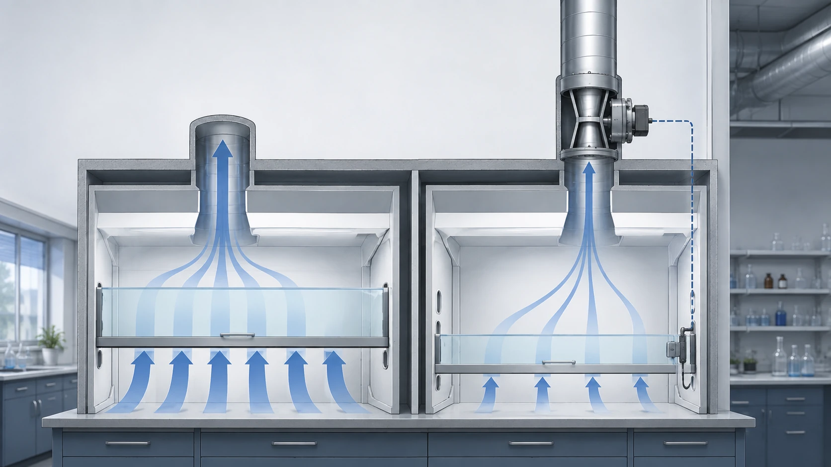
- Choose by usage, not by savings headline — a cav vs vav fume hood decision is a control-architecture call: CAV is constant-air-volume exhaust at a fixed rate, while VAV varies exhaust to hold face velocity as the sash moves.
- VAV saves energy only when sashes actually close — with sashes open at full height a VAV hood exhausts at full flow, so the energy case starts with operator behaviour.
- Match the architecture to your hood population — special-chemistry, high-dilution and simple low-utilization hoods commonly stay on CAV, and only your actual sash patterns decide.
- Never compare savings figures across baselines — every published percentage is a labeled estimate with its own assumptions, never one universal claim.
- Leave with questions, not a quote — the responsibility table and supplier checklist fix who sets face-velocity setpoints, minimum airflow and commissioning acceptance before you commit.
A cav vs vav fume hood search mostly returns pages that crown a winner and quote a savings percentage. That framing hides the decision you face. “Which is better?” is the wrong question; the useful one is which control architecture fits your hood population, how your sashes are used in daily operation, and what the exhaust and supply system around those hoods will cost to run.
VAV is not automatically energy-saving; it earns its keep only when operators close the sashes for enough hours, a condition the energy section develops later in this guide. The guide separates mechanism from marketing, defines both systems precisely, and finishes with the responsibility table and supplier checklist you need to run an effective controls conversation.
CAV vs VAV Fume Hoods: What This Comparison Decides
This first module sets the frame: it names the systems correctly, states the direct answer in one breath, and marks what this comparison will and will not settle.
The Direct Answer: Which Control Architecture Suits Which Project
Choose the control architecture that matches how your hood sashes are used, then verify what the whole system will cost to run. Variable air volume (VAV) fits projects whose hoods sit closed for meaningful hours and whose exhaust and supply systems can follow the sash; that sash-closed condition is what any energy case depends on. Constant air volume (CAV) fits applications that need steady exhaust regardless of sash position — much special-chemistry and high-dilution work — plus simple, low-utilization labs.
Search the question as cav vs vav fume hood or flip it to vav vs cav fume hood; the decision logic stays the same. No single answer covers every lab, because utilization and hood type change the outcome. Later modules turn this direction into a judgment you can defend: the energy conditions that decide whether VAV saves, and the specific situations where CAV remains the right call.
Two Full Names, One Acronym: Constant Air Volume vs “Constant Air Velocity”
Most sources on this topic expand CAV as constant air volume, the wording used by Kewaunee, Mott Manufacturing, TEL and Labconco, among others. One top-ranking comparison page, iQ Laboratory, instead writes “Constant Air Velocity (CAV).” Both expansions circulate for the same acronym, so a reader cross-checking spec sheets can be genuinely misled.
This guide adopts constant air volume and uses it consistently. The label fits the behaviour: what stays constant is the exhaust volume, while air entering the open sash moves at whatever speed that volume produces — the word velocity describes an effect of the system, not the quantity it controls. When you meet “constant air velocity” elsewhere, check the behaviour described instead of trusting the label.
The Scope of This Comparison: Control Strategy, Not Hood Quality
This comparison judges control strategies, not hood brands or build quality. The deciding question is what regulates exhaust volume — a fixed CAV setting or a VAV system that follows the sash — because that choice drives energy use, system integration and the conversation you will hold with controls suppliers. Cabinet quality, containment testing and equipment-level comparisons are separate decisions and are not scored here.
Two boundaries deserve emphasis now. This guide sets no airflow or velocity requirements; those are institutional EHS and design-authority decisions, verified by qualified commissioning, and they are not made on this page. It also asserts no universal energy-savings figure: the numbers that circulate for VAV hoods disagree because their baselines disagree, and the energy section later in this guide reconciles them instead of picking a favorite.
After this module you can name the decision this guide helps you make and state both architectures correctly. The next modules give you the mechanisms — what each system controls, then the energy conditions and fit cases — that turn this frame into a choice you can defend to your team and your suppliers.
Constant Air Volume vs Variable Air Volume: What Each Hood Controls
The two architectures sound similar and behave differently. This module defines each one by what it keeps constant, then shows you how to read the spec fields that tell them apart.
CAV: Constant Exhaust Volume, Regardless of Sash Position or Use
The practical difference between a constant volume vs variable volume fume hood appears in what each system keeps steady. A constant air volume (CAV) hood exhausts the same volume of air at all times: the sash can be wide open, halfway up or closed, and no one needs to be working at the hood, yet the exhaust rate does not change. Manufacturer and university explanations agree on this mechanism — constant exhaust volume regardless of use or sash position — and it is the property that drives everything later in this guide.
Constant volume is not the same as constant face velocity. Because the exhaust rate stays fixed, the speed of the air entering the open sash changes as the sash moves; a smaller opening draws the same airflow through less area, so the inward speed rises. The next module explains that inverse relationship and the bypass variant that softens it. For now, hold the key fact: a CAV system controls volume, and the velocity at the opening is whatever that volume produces across the current sash opening.
VAV: Sash-Following Exhaust Volume at a Face-Velocity Setpoint
A variable air volume (VAV) hood changes its exhaust volume to keep the speed of air at the sash opening steady. When the sash is raised, exhaust flow increases; when it is lowered, flow drops, and the control loop holds face velocity near a setpoint the laboratory defines. Engineering articles and system guides describe the same chain: a sash position or velocity signal, a controller, and an exhaust valve that modulates flow in response.
Put in full words, a variable air volume vs constant air volume fume hood comparison turns on which quantity is controlled: VAV manages the velocity at the opening by modulating volume, while CAV holds volume fixed and lets velocity ride where it lands. The distinction matters because a hood’s energy use tracks exhaust volume, and VAV pays off only when that volume drops in real operation — when sashes close. The hardware behind the behaviour, from sash signal to valve to fan coordination, is mapped in the module on how a VAV system works.
Reading a Hood Spec: Exhaust Volume, Setpoint and Minimum Airflow Fields
Three fields on any hood specification separate the architectures at a glance: rated exhaust volume, face-velocity setpoint and minimum airflow. Rated exhaust volume states the airflow, in cubic feet per minute, the hood is set to move; on a CAV hood this is one operating point, while on a VAV hood it is a range from minimum to maximum. The face-velocity setpoint is the target speed of air entering the open sash that a VAV controller works to hold.
The minimum airflow field matters most on VAV systems: it is the lowest exhaust rate permitted when the sash is closed, set for room ventilation and dilution rather than for face velocity. Who fixes these values deserves attention. The spec lists what a supplier offers or a design intends, but the accepted setpoint belongs to your institution’s EHS and design authority — the number is set by your requirements process, not by the hood hardware alone, so treat every listed value as a starting point to confirm in writing.
If the spec shows a single fixed exhaust number, you are looking at a CAV design; if it shows a range plus a setpoint and a minimum, you are looking at VAV. After this module you can read those fields and say which architecture a hood uses, and you can explain in one sentence what each system keeps constant. The next module shows why closing the sash on a CAV hood raises face velocity, and how the bypass variant changes that behaviour. Decide what to do now: read each hood spec’s exhaust fields, identify the architecture, and list the setpoint values your EHS must confirm in writing before you compare quotes.
Why Sash Position Drives Face Velocity on a CAV Hood — and the Bypass Variant
On a CAV hood the sash is a control input the system ignores. This module explains the coupling that makes sash position matter anyway, and the bypass variant that changes the outcome.
The Coupling: Exhaust CFM Equals Face Velocity Times Open Sash Area
Exhaust volume, face velocity and the sash opening are tied by one relation: exhaust airflow equals face velocity times the open sash area, where airflow is measured in cubic feet per minute and area in the square feet of opening the sash leaves exposed. Face velocity is the speed at which room air enters that opening. The hood’s exhaust system sets the volume; you set the area by where you leave the sash; the velocity is the quotient the two produce together.
Treat the relation as mechanism education, not as a sizing exercise. Working out airflow for a specific hood, duct run and room is covered by a dedicated airflow-calculator guide, and this page does not repeat the sizing math. What matters here is the shape of the relation: with volume held fixed, velocity and area move in opposite directions, and that single fact explains the behaviour in the next two sections.
Closing the Sash on a CAV Hood Raises Face Velocity
To understand cav fume hood sash closed face velocity, start from the coupling above. A constant volume system holds its exhaust rate while the sash changes the open area, so the same airflow must pass through a smaller opening and the inward speed climbs as the sash lowers. University EHS material and several engineering articles describe this as an inverse relation: because exhaust volume stays constant, face velocity changes inversely with sash height.
The rise matters in practice. Suppliers caution that high inward speeds can disturb work near the sash opening and push the hood’s airflow pattern away from its designed operating point, which is part of why a hood left shut on CAV is not behaving as the design assumes. One manufacturer, Mott Manufacturing, reports that face velocity on a CAV hood can rise by 2.5 times or more as the sash closes; that specific figure stays attributed to the vendor, while the direction of the effect is the general mechanism every source describes.
Bypass Hoods: The CAV Family That Limits the Velocity Rise
A bypass hood is a CAV variant that softens the coupling rather than breaking it. It adds a bypass opening above the sash, so as the sash closes, part of the exhaust is drawn through that secondary opening instead of across the sash face; the volume crossing the sash opening falls even though total exhaust volume stays constant. University EHS material describes the same intent: the bypass keeps face velocity more stable as the sash approaches closed.
Treat bypass as a design difference inside the CAV family, not as variable-volume control. Total exhaust volume is still constant — the system does not modulate to follow the sash — so the energy profile of a bypass hood resembles other CAV hoods more than it resembles VAV. If the goal is exhaust volume that genuinely falls as the sash closes, that is the variable air volume architecture from the previous module, not a bypass hood.
After this module you can predict what a closing sash does to face velocity on any CAV hood, tell a bypass hood from a plain one, and separate the mechanism from the requirements question. The numerical face-velocity values a project must meet are set in requirements guides and by your institution’s EHS and design authority; this page explains the mechanism, not the mandate. Decide with your own hoods in mind: before you accept a CAV spec, check whether it is a plain or bypass design, predict the closed-sash velocity rise, and send the velocity question to your EHS or requirements owner — not to the hood brochure.
How a VAV Fume Hood Works: From Sash Signal to Exhaust Valve to Fan
VAV turns a sash movement into a coordinated change across the whole exhaust and supply system. This module walks the chain from the signal at the hood to the fan that moves the air.
What VAV Measures: The Sash Position and Velocity Signal
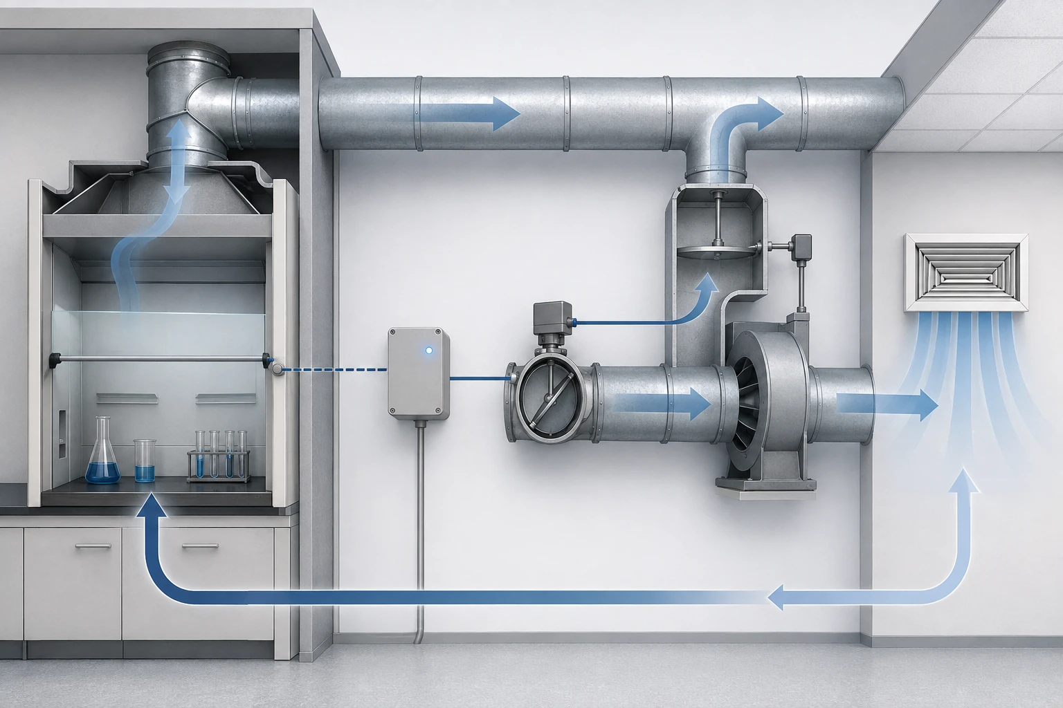
A VAV system begins with a measurement: where is the sash, and what is the airflow doing? Position sensors on the sash frame track how far the sash is open, while velocity-based inputs measure airflow in the exhaust duct as a proxy for conditions at the opening; either way, the controller needs a live signal of what the operator is doing. Manufacturer education pages and system guides agree that the sash signal is the trigger the whole loop reacts to.
The sash sensor is the only part of the chain that lives on the hood; the rest sits upstream in the exhaust and control system. Because VAV exists to respond to the sash, a slow or unreliable reading weakens every downstream component. Who supplies, calibrates and accepts the sensor is one of the responsibility questions the table near the end of this guide answers.
How the Valve and Controller Hold the Setpoint
The controller takes the sash signal and commands the exhaust valve — a control damper or a venturi valve — to move exhaust volume toward the rate that keeps face velocity at its setpoint. The loop runs continuously: the controller compares the measured condition with the target and trims the valve until the two match. Both valve families perform this work; they differ in response and stability, a component choice covered later in this guide.
Fume hood vav control is exactly this loop of measurement, decision and valve movement, which is why VAV hardware cannot be judged as a hood option alone. The controller may be a dedicated hood controller or part of the building automation system, and the valve is usually inside the controls scope rather than the cabinet scope. Keep that split in mind: when a supplier quotes VAV, ask which parts of the chain the quote actually covers.
Beyond the Hood: Duct Pressure, Fan Capacity and Makeup Air
One valve closing changes pressure across the whole exhaust duct. When several hoods modulate at once, the system holds balance through duct-pressure monitoring and fan-capacity control: as valves close and duct pressure rises, the fan trims or a bypass plenum opens to absorb the difference, so one hood’s movement does not starve or overdrive its neighbours. System guides describe these as coordinated control loops rather than a single valve acting alone.
The supply side has to answer the exhaust side. Laboratories that exhaust large air volumes typically need makeup air — conditioned replacement air from the supply system — and supply fans and dampers must track the exhaust so the room stays balanced. That is why how does a vav fume hood work is a system question: the honest answer is a sensor, a valve and controller, a coordinated fan, and supply air acting as one loop, not a valve bolted onto a hood. The energy consequences of that whole-system behaviour come next.
After this module you can name every link VAV depends on — sash signal, valve and controller, duct-pressure and fan coordination, makeup air — and you can see why no single hood saves energy by itself on VAV. The energy logic, and the operating condition that turns this system into savings, are the subject of the next module.
Fume Hood Energy Use: Where a CAV vs VAV Fume Hood Decision Is Made
Energy is where the CAV and VAV decision gets real, and it is also where marketing does the most damage. This module follows the money, states the one condition that produces savings, and shows why published savings numbers cannot be compared as if they measured the same thing.
Exhaust Volume Drives the Cost of Conditioning Replacement Air
A fume hood’s operating energy is dominated by the air it exhausts, because every cubic foot that leaves the hood must be replaced. The replacement air is outside air that has to be filtered, cooled or heated, and humidified or dehumidified before it enters the laboratory, and that conditioning work is the recurring cost of running the hood. Mott Manufacturing states the point directly: the “vast majority of energy savings will come from reducing the costly supply air.”
Exhaust volume is therefore the quantity that matters for energy, and reducing the volume a hood exhausts reduces the volume of conditioned air the building must deliver. The link between airflow and energy is well established in technical articles and system guides, and the cost side matters most in buildings with heavy makeup-air duty, where nearly all exhausted air is replaced by conditioned supply air. The local cost of a unit of conditioned air varies with climate, utility rates and hours of operation, so this guide deliberately gives no universal cost per unit of airflow; that number belongs to your project’s own analysis.
The Condition for Savings: Sashes Must Actually Close
Asked directly, does a vav fume hood save energy? Only when the sash is closed or down at its minimum operating position. With the sash open at full height, a VAV system exhausts at full flow, exactly like a CAV hood, and there is nothing to save; Labconco’s engineering article makes the same point, describing no energy or operating-cost benefit unless the operator closes the sash. Mott Manufacturing puts the risk more bluntly: leave the sash open on a VAV system and you have paid for variable control while operating “effectively CAV.”
So when does VAV save energy? Only during the hours the sash is closed and the system responds to it. That depends on operator behaviour, occupancy patterns and a functioning chain of sensors, valves and controls, which is why savings claims are always conditional rather than automatic. Any serious evaluation of VAV starts by asking how many hood-hours per day the sashes can realistically be closed.
Minimum Airflow at a Closed Sash: The Concept, Not a Universal Value
Minimum airflow is the lowest exhaust rate a VAV system permits when the sash is closed, and it is not zero. A closed sash still needs some exhaust for room safety and dilution reasons and to keep the duct system stable, so every VAV design carries a floor below which the controller will not trim. In practice, a project’s vav fume hood minimum airflow is set by your EHS and ventilation engineering for those reasons; there is no universal value that fits every laboratory.
One vendor-model example illustrates the concept without becoming a rule. Labconco’s footnote models the closed-sash exhaust volume at 25 CFM per cubic foot, citing NFPA 45 guidance in its stated assumptions; that figure is the vendor’s modeling basis for its own savings illustration, not a statement of what NFPA 45 requires and not a number to copy into your specification. When a supplier proposes a minimum airflow for your project, ask what safety and room-ventilation reasoning produced it, and confirm the accepted value with your EHS and design authority in writing.
Why Published Savings Numbers Disagree: Baselines and Assumptions
Published savings figures for VAV disagree because they start from different baselines and carry different assumptions, not because one author is honest and another is not. The table below keeps each claim with its own institution, number, baseline and conditions, so the differences stay visible instead of being averaged away.
| Source type and institution | Number (original wording preserved) | Baseline | Assumptions and conditions |
|---|---|---|---|
| University planning model — UIUC iCAP (2010 archive, Trane TRACE) | Modeled cost of conditioning air ≈ $5,500 per hood-year for CAV; ≈ $2,100 for VAV; ≈ $3,200 for CAV with heat recovery; ≈ $1,500 for VAV with heat recovery; campus target of roughly 70% reduction in CAV energy via VAV plus heat recovery | One campus’s existing CAV hood fleet | Institutional plan targets from a single university, modeled with heat recovery included in the 70% figure; planning estimate, not measured performance |
| Manufacturer technical article — Labconco (footnoted model) | VAV on a standard hood: modeled savings 30–50% | Standard hood at 100 fpm, fully open | Footnote assumptions: $7.00 per CFM per year (regional range $5–$12), 6,240 operating hours per year, closed-sash exhaust volume modeled per NFPA 45 guidance; vendor illustration, not a measured result |
| Manufacturer self-report — TEL (UK) | Self-reported research result “up to 85%”; client case at Reading University of £223,958 per year with payback under four years on 44 fume cupboards | TEL’s own research and one UK university installation | Vendor self-report and a single case in UK currency and units; included here as an example of a claim to interrogate, not as a general result |
Each row answers a different question against a different baseline, which is why no row can be subtracted from or averaged with another. The honest reading of any “VAV saves X%” figure, from any supplier, starts with three questions: what was the baseline, what assumptions were modeled, and what sash behaviour was assumed? This guide deliberately asserts no universal savings percentage and no universal payback period; those numbers only exist inside a project’s own baseline and operating profile.
Worked example — walking a two-hood decision. Take a hypothetical teaching lab with two identical six-foot hoods (round numbers for illustration only): a 100 fpm design face velocity across a 20 ft2 full-open area means 2,000 CFM by the coupling formula. Hood A stays on CAV and exhausts 2,000 CFM around the clock whether anyone is working or not. Hood B runs on VAV with a closed-sash minimum airflow set by the project’s ventilation engineer — a project number, not a universal one — so it exhausts 2,000 CFM only while its sash is open and trims toward that minimum whenever the sash closes.
If the lab’s sashes are open about four hours a day and closed the rest, Hood B moves a fraction of Hood A’s daily air volume: that is the mechanism from earlier in this module, not a marketing percentage. The dollar value depends on climate, utility rates and hours, so the example stops at volume — put your own numbers in, keep the baseline fixed, and let the reconciliation questions decide. This is the shape of the comparison, not a measured saving claim.
After this module you can state the condition that makes VAV save — the sash closed to its minimum — and you can reconcile any published savings claim by asking for its baseline and assumptions. The next module turns the frame around and covers the situations where constant volume remains the right choice.
When Constant Volume (CAV) Is Still the Right Fume Hood Choice
Everything so far has explained why VAV can save energy. This module gives the other side of the decision its full weight: the applications and operating profiles where constant volume remains the better answer.
Special-Chemistry and High-Dilution Hoods Commonly Kept on CAV
For some applications, constant exhaust is a feature rather than a limitation. Hoods handling perchloric acid, radioisotopes or hydrofluoric acid are commonly kept on CAV systems, where the simpler exhaust path supports washdown and decontamination routines and operators value predictable, always-on airflow over modulation. Digestion and high-heat processes that generate heavy fume loads often stay on CAV as well, or on VAV with higher minimum airflow settings, because those loads need steady dilution volume rather than sash-following modulation.
Read that list as industry practice, not as a mandate. Mott Manufacturing, whose engineering article is the most balanced treatment in this space, describes these choices as common practice with sound reasons; no code requires CAV for these hoods, and some installations run them on VAV with elevated minimums. Dedicated requirements for these hood types are covered in separate guides; here it is enough to know the applications exist and that they shift the balance toward constant volume.
Simple or Low-Utilization Labs Where CAV Is Defensible
CAV also stays defensible where there is little to modulate. A lab with a few hoods used for short periods each day, or a room whose ventilation is set by space requirements rather than sash activity, gives a VAV system little closed-sash time in which to save money. The variables that change the conclusion are utilization, hood density, climate and energy prices, and the ventilation target for the room: high utilization, dense banks of hoods, expensive conditioned air and heavy makeup-air duty push the balance toward VAV, while sparse use and simple rooms pull it back toward CAV.
These directions matter more than any borrowed payback figure, which is why none appears here. Estimate your own hood-hours with sashes closed and the cost of conditioning that air in your climate, and the architecture usually chooses itself. When the answer is close, the decision has moved from architecture to project specifics.
The First-Cost Trap: Why “Cheaper to Buy” Is Not a Complete Argument
The most common argument for CAV is that it costs less to buy, and a constant volume system does carry a simpler first-cost profile. The trap is ending the comparison there: the energy bill for conditioning replacement air recurs for the life of the laboratory, so a modest first-cost saving can look small next to years of operating cost on hoods that run constantly. Mott Manufacturing cautions against choosing constant volume purely to cut first cost, and the supply-air cost logic from the energy module is the reason.
The caution runs both ways. VAV is worth its added hardware and commissioning cost only if sashes will close for enough hours and the system will be commissioned and maintained properly; a VAV system that runs with sashes open, or with drifting sensors, reproduces exactly the kind of unfounded savings claim the energy module told you to interrogate. The honest test of either architecture is behavioural and systemic, not just budgetary: closed-sash discipline and commissioning quality decide whether the VAV premium earns itself.
If this module pushes you toward VAV, the next sections cover the hardware choices and the retrofit scope, and every route converges on the responsibility table and supplier checklist at the end of this guide. After this module you can decide, for your hood population and usage, whether CAV is still the right call or whether the VAV route is worth pursuing — or you can name the missing inputs that keep the decision open.
VAV Hardware: Control Dampers vs Venturi Valves on the Exhaust Path
Once a project commits to VAV, the component question — fume hood venturi valve vs damper — comes up quickly, because both devices occupy the same spot in the exhaust path yet behave differently. This module explains what each one does and turns the choice into questions for the supplier.
How an Exhaust Control Damper Modulates Flow in a VAV Loop
A control damper is the adjustable gate of the exhaust path: a blade inside the duct that rotates to enlarge or shrink the flow area. In a VAV loop, the controller drives the damper toward the position that produces the commanded exhaust volume, so small changes in blade angle translate into changes in airflow through the hood. This is the same valve family the system chain described in the module on how VAV works, now examined as a component.
Because a damper sets volume by adding resistance, its behaviour is tied to the pressure across it: at a fixed blade position, a change in duct pressure changes the flow. That coupling is normal and manageable, and it is precisely the behaviour to clarify with a supplier for your duct design, since duct layouts differ from one laboratory to the next.
What a Venturi Valve Does Differently
Controls and valve suppliers describe a venturi-style exhaust valve as a device with a shaped internal profile, typically a movable cone or plug, designed so that flow stays close to the commanded value across a range of duct pressures. Where a plain damper relies on the controller correcting for pressure effects, the venturi geometry carries part of that regulation itself, with the actuator adjusting the flow setpoint rather than continuously chasing pressure swings.
Neither family wins in the abstract. The two approaches trade regulation behaviour, moving parts, pressure handling and maintenance traits, and the right fit depends on your duct system, your control scheme and the supplier’s application engineering. That is why this choice belongs in a conversation with technical detail, not on a one-line specification comparison.
Choosing a Valve Type: Inputs for the Supplier Conversation
Product options such as a VAV control damper and a venturi air valve carry supplier-specific designs; treat the names as options to evaluate rather than claims to accept. Ask how the valve behaves at the minimum airflow point, how sensitive it is to duct-pressure changes, how it is calibrated together with the controller and actuator, and what failure modes and alarms the system reports.
Those answers, not the valve’s brand or name, decide whether the component fits your duct design and controls architecture. Collect them now; the complete supplier conversation checklist appears in the final module of this guide.
After this module you can frame the damper-versus-venturi questions your project needs answered, without treating either component as a universal preference. The next module covers the retrofit path for laboratories converting existing CAV hoods to VAV.
Converting a CAV Fume Hood to VAV: What the Retrofit Involves and Who Verifies It
For laboratories with existing constant volume hoods, the retrofit path is where the controls decision meets the project budget. A cav to vav fume hood conversion is rarely a single-part swap; this module scopes what changes and who proves the result.
What a Conversion Actually Replaces: Valve, Signal, Controller and Coordination
Converting a CAV hood to VAV usually involves more than replacing one component. Typical scope spans the exhaust valve or the addition of a venturi device, a sash position or velocity signal, a controller that closes the loop, and the coordination that makes the change real: duct-pressure and fan-capacity response, makeup-air tracking, and then the setting and commissioning of the whole loop as one system.
How deep the conversion goes depends on what already exists. A hood with a controllable valve and a building automation system that can accept the new signal may convert more cleanly than one with a fixed damper and no controls backbone. The honest first step is an audit of the existing valve, actuator, controller and building-management integration, not a request for quotes.
Who Verifies the Outcome: Commissioning and Re-Test, Not the Vendor Estimate
The core rule for any conversion: whether the promised savings arrive is judged by a project acceptance procedure — commissioning plus any containment or performance re-test — not by the supplier’s estimate. A modeled saving is a target; measured performance under defined operating conditions is the evidence, and the two only mean something when compared on the same baseline. One university’s conversion plan illustrates the target-making side: its roughly 70 percent reduction goal for CAV energy is a modeled institutional target that assumes heat recovery, not a measured commitment from a completed project.
Because savings figures only carry meaning relative to a baseline, a conversion evaluation must meter before and after on the same basis; the reconciliation lesson from the energy module applies directly here. Containment or performance re-test work is covered in its own dedicated guide, and face-velocity setpoint acceptance sits with the institution’s EHS and design authority. Book those responsibilities into the project before the retrofit starts: who re-tests, against what criteria, and under which operating conditions decide whether the conversion worked.
What to Bring to the Supplier Before a Conversion Quote
Before asking for a conversion quote, assemble the inputs: the current exhaust configuration and valve type, the existing controller and building-management integration, records of sash and occupancy behaviour, and the minimum-airflow and face-velocity setpoints your EHS accepts. Combine these with the valve questions from the previous module — behaviour at minimum airflow, sensitivity to duct pressure, calibration and failure modes — so the quote answers your project rather than a generic template.
Ask the supplier to state in the proposal what they will verify and what the acceptance criteria will be, and keep their savings estimate labelled as an estimate until commissioning data exists. The full supplier conversation checklist in the final module collects every one of these questions in one place.
After this module you can scope what a conversion replaces, name the party who verifies the outcome, and list the inputs a supplier quote should answer. The final module brings every thread together into the responsibility table, the supplier checklist and the next-step path. Before you sign anything, decide your acceptance posture now: name who will verify savings, against which criteria and baseline, and put that into the request for quotation rather than after the invoice.
Fume Hood Controls: Responsibility Table, Supplier Checklist and Next Step
Every earlier module ends in questions that belong on someone’s desk. This final module turns them into two working documents — a responsibility map and a supplier checklist — and points the conversation to its natural next step.
Hood vs Controls Responsibility: Who Supplies, Who Accepts, Who Sets the Parameters
The most common failure in a fume hood controls project is an ownership gap: the cabinet maker, the controls vendor and the laboratory each assume another party is handling the setpoints, the signal or the acceptance. The table below assigns each link of the chain to a functional role. The roles are categories of responsibility, not endorsements of any company, and the table is compiled from the system-chain and integration sources discussed earlier in this guide.
| Link in the chain | Who supplies | Who sets the parameters | Who accepts |
|---|---|---|---|
| Hood cabinet and exhaust connection | Hood supplier | Project team with design input | Project acceptance at delivery and commissioning |
| Controller (dedicated hood controller or building automation) | Controls vendor | Controls engineer, within EHS-approved setpoints | Commissioning agent with the laboratory |
| Exhaust valve (control damper or venturi valve) | Controls or valve vendor | Controls engineer with system design | Commissioning agent |
| Sash position or velocity sensor | Controls vendor | Calibrated with the controller during commissioning | Commissioning agent |
| Airflow setpoints (face velocity and minimum airflow) | None — a design decision | EHS and design authority | EHS, verified by qualified commissioning |
| Commissioning and acceptance re-test | Qualified commissioning agent | Project acceptance criteria | Institution or EHS signs off |
Use the table to force one conversation you would otherwise avoid: name the supplier and the accepting party for every row before purchase. A project that can fill all six rows with named roles has done most of the work that prevents retrofit disappointment.
Supplier Conversation Checklist: Questions to Send Before You Commit
Send this checklist with any request for quotation so the answers come back comparable across vendors. Each item is a question or requirement, not a specification, and none of them commit you to a number.
- Describe the control architecture you propose for each hood group — constant volume, variable volume, or a mix — and where the controller lives.
- State who sets the face-velocity setpoint and who accepts it, and confirm that the acceptance process runs through our EHS and design authority in line with the requirements guidance.
- Give the minimum airflow you propose at a closed sash for each hood, and the safety or room-ventilation reasoning behind it.
- Specify the valve type — control damper or venturi valve — and show how it fits the existing duct and controls.
- Explain how each hood loop coordinates with duct pressure, fan capacity and makeup air in our building.
- Describe the alarm conditions and failure modes, and what the system does if the sash signal is lost.
- Define the commissioning scope, who performs it, and who carries out the acceptance re-test.
- For a retrofit, confirm that before-and-after measurements use the same baseline and metering method.
Treat the answers as the beginning of your specification, not the end of it. Any vendor who cannot answer item 2 or item 7 in writing is not yet ready to quote your project.
Where the Next Step Leads: Fume Hood Controllers and VAV Components
When you take the responsibility table and the checklist to the market, evaluate the controller and the valve as one system rather than two separate purchases. A fume hood controller is the component that closes the control loop described throughout this guide, and it should be quoted together with the VAV control damper or venturi air valve it will drive. A low-flow high-performance fume hood is an adjacent equipment path worth examining when your process can reduce exhaust at the source.
The product pages for those options are the places to test supplier claims against your own requirements; nothing in this guide asserts a product specification, price, lead time or performance result for any of them. Start the conversation where the system starts: bring your sash-usage profile, your hood list and this checklist, and ask how the controller, the valve and the building system will be quoted, configured and verified together.
What This Guide Does Not Decide for You: Setpoints, Requirements and Acceptance
Three decisions deliberately stay off this page. Face-velocity setpoints, institutional requirements and acceptance criteria belong to your EHS and design authority, verified by qualified commissioning; this guide explains the mechanism, and the dedicated requirements and testing guides carry the detail. No universal savings percentage or payback period is asserted anywhere here, because those figures only exist inside a project’s own baseline, which is why the energy module kept every published number labelled as an example.
You leave this guide with a responsibility table and a set of questions, not a quote — that is the intended result. Take the checklist to a controls supplier, take the answers back to your EHS and design authority, and the cav vs vav fume hood decision will settle itself on your own numbers, your own sash behaviour and your own acceptance criteria.
Leave a Reply