


Description
PP Motorized Iris Damper for Measured Laboratory Airflow
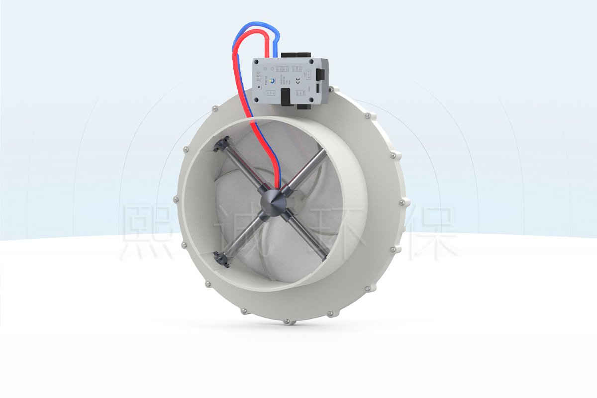
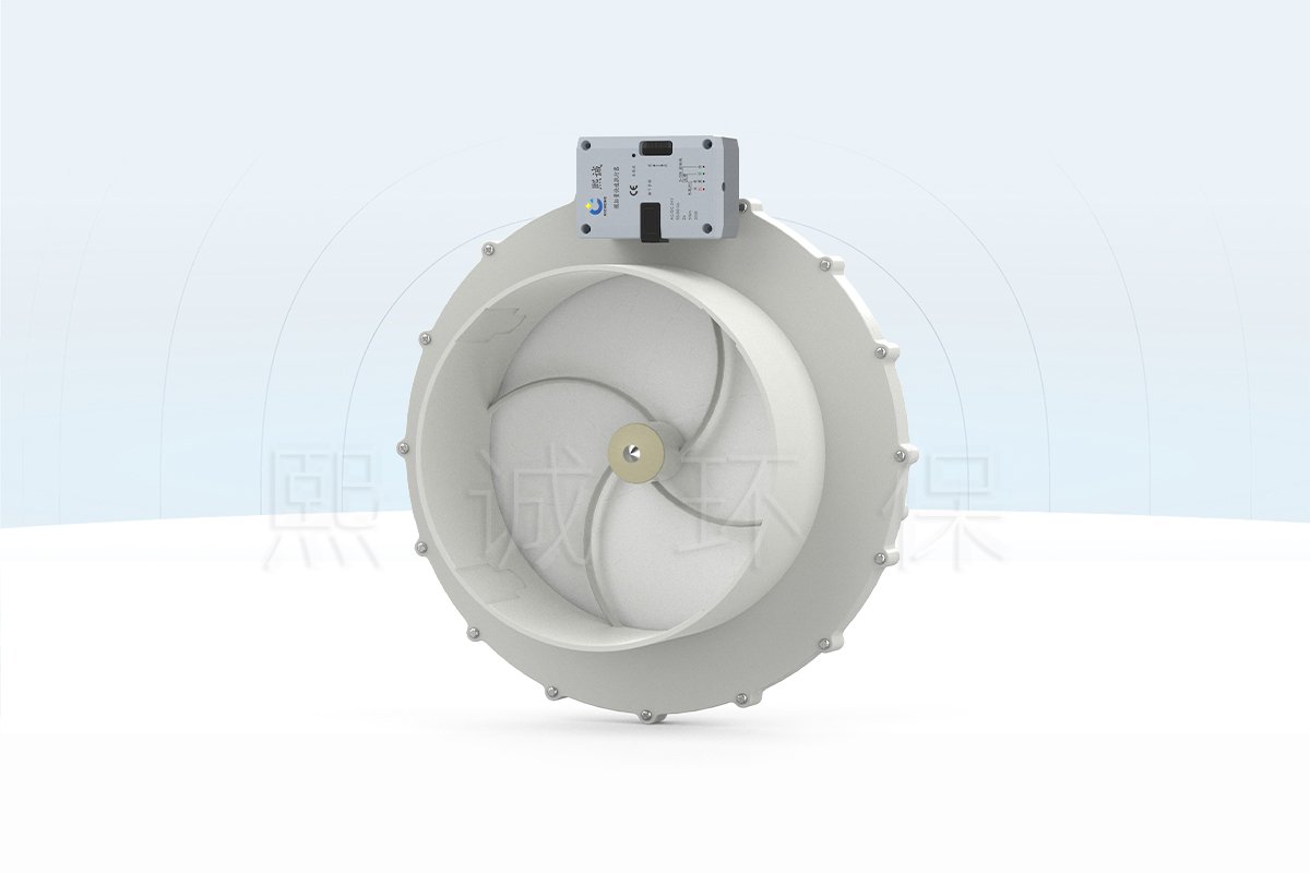
A PP motorized iris damper regulates airflow through a circular duct by moving several overlapping blades toward or away from the center. The aperture remains concentric as it changes, which distinguishes this mechanism from a single rotating butterfly blade. XICHENG combines the polypropylene iris body with an airflow-measurement section and either an analog actuator or an integrated airflow-control actuator.
The product is intended for projects that need more than a manually balanced iris. It can accept a control command, change the duct opening and participate in a measured airflow sequence. Depending on the selected package, that sequence can serve a laboratory supply or exhaust branch, room supply/exhaust tracking, or a fume hood system that relates airflow demand to sash position or face velocity.
What the Product Includes
The base assembly includes the round PP body, concentric PP iris blades and the mechanical drive required to move the aperture. The automated package adds the selected actuator. A measured-control configuration can also include the airflow sensor, controller, local panel connection and communication interface needed by the approved control sequence.
These items must be separated on the quotation. The presence of an actuator does not prove that a complete airflow loop is included, and the presence of a measuring section does not define the sensor range, calibrated airflow relationship or final control accuracy. The valve schedule should identify the damper body, actuator, measurement device, controller, panel, wiring accessories and BMS scope for each tag.
Choose This Product Family When
- The duct is round and the project benefits from a centered, progressively changing aperture.
- Polypropylene construction is preferred for a laboratory or process-ventilation air stream.
- Airflow must be adjusted automatically from an analog command, controller setpoint, sash signal, face-velocity input or room-control sequence.
- The design can provide the minimum, normal, maximum and emergency airflow requirements together with the available duct pressure.
- The project will commission the airflow sensor and actual branch performance instead of accepting actuator position as proof of airflow.
The product is especially relevant where a compact round regulating section is needed and where the control designer wants the iris body, actuator and measurement arrangement supplied as one coordinated assembly. The illustrated reference is a 250 mm unit; other sizes should not be assumed until a project drawing is returned.
Do Not Select It as a Generic Shutoff Damper
This motorized iris damper is a regulating product. No published leakage class, fire rating, smoke-control rating or certified isolation duty is assigned to the family. It should not replace a fire damper, smoke damper, blast damper, backdraft damper or positive shutoff valve.
It is also not a Venturi air valve. A Venturi product uses a shaped body and pressure-compensating mechanism to maintain a defined airflow relationship as duct pressure changes. The PP iris damper can be used in a closed-loop airflow system, but pressure independence is not inherent or established by the product name. Where that behavior is required, evaluate the VAV Venturi Air Valve and its project-specific operating range.
Key Specifications and Published DN250 Dimensions
The table below separates verified family information from fields that must be finalized for the supplied valve tag. The 250 mm dimension drawing is a reference configuration, not evidence of a complete standard size range. Confirm the final body drawing before duct fabrication or support placement.
Verified Reference Data
| Specification | Verified Reference | Selection Note |
|---|---|---|
| Product mechanism | Motor-driven concentric iris aperture | Multi-blade regulating mechanism for a round duct |
| Body and iris blades | Polypropylene | Confirm grade and all exposed components against the air stream |
| Reference duct diameter | 250 mm | Only the illustrated 250 mm configuration is presently documented |
| Reference overall height | 182 mm | Reserve actuator, cable and service clearance in addition to this envelope |
| Actuator packages | Analog actuator or integrated control actuator | Select by command, measurement, controller and BMS requirements |
| Power | DC 24 V +/-10%, max. 18 W; AC 24 V +/-10%, max. 40 VA | Confirm the exact package load and circuit protection |
| Analog actuator travel | 5 seconds for full opening or closing | Travel time is not the complete airflow-loop response |
| Communication | Modbus RTU with the applicable controller | Confirm point map, address, baud rate and termination |
| Panel connection | RJ12 | Confirm panel model, cable length and supplied scope |
| Operating ambient | 0 to +50 C; 10-95% RH, non-condensing | This is an equipment ambient limit, not an air-stream limit |
| Storage ambient | -20 to +50 C; 10-95% RH, non-condensing | Protect the assembly from moisture, impact and contamination |
DN250 Mechanical Envelope
The reference image identifies a 250 mm circular connection and an overall height of 182 mm. The actuator and tubing occupy space beside the body, so the duct layout must include access for wiring, pressure tubes, manual inspection and future removal. The image does not define the required support method, joint allowance or straight-duct length.
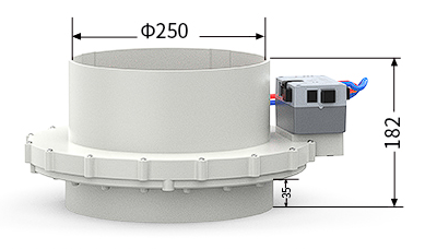
Use the returned project drawing to coordinate duct centerline, body orientation, actuator access and pressure-tube routing. If a size other than 250 mm is required, request a separate dimensional proposal rather than scaling this drawing.
Data That Remains Project-Specific
Airflow range, pressure drop, allowable differential pressure, measurement accuracy, sensor range, leakage, process-air temperature and sound performance are not defined as universal family values. They depend on the selected aperture, sensor, control package, duct geometry and operating point. The quotation should return the applicable values or identify them as commissioning targets.
The five-second actuator value describes mechanical travel for the analog configuration. A complete airflow command includes sensor response, controller processing, actuator movement, duct pressure change and stabilization. Where response time affects fume hood safety or room pressure, specify the acceptance test and measure the installed system.
PP Iris Body and Concentric Aperture Principle
The iris mechanism uses several overlapping blades linked so that they move together around the duct centerline. Closing the mechanism reduces the opening concentrically; opening it retracts the blades toward the outer body. This geometry creates a centered restriction instead of turning one blade across the full duct diameter.
How the Iris Restricts Airflow
Airflow changes because the effective opening area changes. The relationship between actuator position, aperture area, pressure difference and airflow is not automatically linear. The same blade position can produce different airflow when fan pressure, upstream resistance or downstream system conditions change. For that reason, position command alone is suitable only when the control basis accepts position as the controlled variable.
For measured airflow control, the system needs an airflow sensor and a controller that compares measured airflow with the active setpoint. The controller then moves the actuator until the measured value reaches the target. The aperture is the final control element; it does not replace the sensor, controller, fan or commissioning work.
A concentric opening can be useful where the designer wants the flow path to remain centered and where cleaning access benefits from opening the iris. These characteristics do not eliminate pressure loss or installation effects. The selected operating point must be reviewed against the available fan pressure and the measurement arrangement.
Material and Air-Stream Review
The body and iris blades are identified as PP. That supports corrosion-conscious laboratory applications, but the word polypropylene does not establish compatibility with every chemical mixture, concentration or temperature. The material review must include the actual PP grade, blade surfaces, linkages, fasteners, sensor parts, tubing, seals and any components exposed to vapor, aerosol or condensate.
Provide the expected chemicals, concentration range, process and cleaning temperature, humidity, condensate behavior and upset conditions. Where the air stream can deposit crystals, sticky residue or particulates, consider how buildup could affect overlapping blade movement and the measurement section. Maintenance access may be more important than nominal material resistance alone.
The PP iris damper should not be selected for hot gas, abrasive solids or solvent exposure solely from the body image. A project-specific material schedule is required. If the air stream exceeds the verified PP configuration, use another approved body material or a different airflow-control product.
Measurement Section and Pressure Conditions
The XICHENG configuration includes a measuring section and airflow sensor. The final airflow result still depends on sensor range, tubing integrity, pressure pickup location, calibration, density assumptions and nearby duct disturbances. The sensor must be selected for the minimum as well as maximum airflow; an oversized range can reduce useful resolution at low demand.
Upstream elbows, branches, transitions, fans and dampers can distort the velocity profile. The layout should reserve the straight-run conditions stated in the project submittal, or the supplier should approve an alternative arrangement. Pressure tubes must remain identified, unkinked, leak-free and protected from condensation. Reversing high and low connections can produce an invalid reading even when the actuator moves normally.
Where duct static pressure varies widely, the control authority and sensor signal must remain usable across the operating range. If the project requires a documented pressure-independent mechanism rather than closed-loop correction, compare the iris damper with a VAV Venturi Air Valve. The mechanisms solve different design problems and should not be treated as interchangeable.
Actuator, Sensor and Control Package Options
The same PP iris body can be supplied with two different automation approaches. The analog-actuator configuration receives a positioning command and moves the aperture. The integrated airflow-control configuration adds the sensing and control functions required to regulate a measured variable. Selecting between them depends on what the building or laboratory control system commands and what feedback it must receive.
Analog Actuator Configuration
Use the analog configuration when an external controller already calculates the required damper position or airflow command and the iris assembly only needs to execute that signal. The verified actuator reference completes a full opening or closing movement in five seconds. Intermediate positions can be used when the command and actuator package are configured for modulating control.
This arrangement can simplify the valve assembly, but it moves responsibility for sensing, setpoint logic, alarms and BMS integration to the external controller. The controls schedule must state the command range, feedback range, direction of action, power supply, loss-of-signal behavior and required proof of position. A percentage-open signal is not an airflow measurement.
Integrated Airflow-Control Configuration
The integrated configuration is used when the damper assembly must measure airflow and adjust the iris aperture toward an active setpoint. The package can include the airflow sensor, controller, actuator, RJ12 panel connection and Modbus RTU interface. It is suited to a duct branch where the required airflow changes according to occupancy, room balance or laboratory equipment demand.
Selection requires the minimum, normal, maximum and emergency airflow values. The sensor range must resolve the lowest required flow while remaining within range at the highest condition. The controller also needs the available pressure, control direction, alarm limits and permitted response. These values must be returned in the submittal rather than inferred from a generic actuator label.
| Decision Field | Analog Actuator | Integrated Airflow Control |
|---|---|---|
| Primary command | External position or modulating signal | Airflow or system setpoint processed by the supplied controller |
| Measured airflow loop | Provided by the external control system when required | Included when the selected sensor and controller are specified |
| Verified travel reference | 5 seconds full open/full close | Final loop response depends on sensor, logic, actuator and duct system |
| Communication | Defined by the external controller | Modbus RTU with the applicable package |
| Best fit | Projects with an established external control architecture | Measured branch airflow, room tracking or fume hood sequences |
| Quotation must identify | Signal, feedback, power, direction and fail position | Sensor, range, setpoints, alarms, point list and commissioning scope |
Fume Hood and Room-Control Sequences
For fume hood service, the airflow demand may come from sash position, face velocity or an approved combination of both. An FHC10-based package can coordinate the measured exhaust flow with the selected hood sequence. The hood still requires a defined containment target, sensor location, alarm strategy, minimum airflow, emergency exhaust mode and field acceptance test.
For duct or room supply/exhaust service, a QAVC10-based package can regulate measured branch airflow. Room pressure control requires more than one damper: the system must coordinate supply, general exhaust, equipment exhaust, door state and the room differential-pressure sensor. The iris damper executes its assigned branch command; it does not independently define the room-control sequence.
BMS and Fail-State Requirements
Modbus RTU can expose operating values and commands when the selected controller supports them. Before order, define the physical layer, register map, units, writable points, alarm behavior, device address, baud rate, parity, termination and responsibility for network commissioning. The local RJ12 port should not be treated as a substitute for the BMS interface without confirming the supplied panel and wiring.
Specify what happens after loss of power, command signal, sensor signal or communication. The required response may be hold position, drive open, drive closed or move to a defined emergency position. The correct choice depends on the laboratory risk assessment and fan sequence. It cannot be assigned as one universal family behavior.
Applications, Product Comparison and Selection
The PP motorized iris damper is best evaluated as a measured, modulating round-duct product. It is not selected only by diameter. The airflow schedule, pressure conditions, material exposure, control architecture and installation envelope determine whether the iris mechanism is the right choice.
Suitable Laboratory Applications
Typical applications include laboratory supply branches, general exhaust branches, equipment ventilation and room supply/exhaust tracking. The PP construction can be useful where the air stream or surrounding environment makes a non-metallic body preferable, subject to a complete compatibility review.
A fume hood iris damper can participate in sash-position or face-velocity control when it is paired with the appropriate hood controller and sensors. It is not a complete fume hood safety system by itself. The exhaust fan, hood controller, alarm, airflow or face-velocity sensor, room balance and commissioning procedure remain part of the system design.
Do not apply the standard page to fire or smoke control, blast protection, passive backdraft prevention, liquid service or certified gas isolation. Applications involving corrosive condensate, crystallizing vapor or particulate buildup need specific review of blade movement, measurement ports and cleaning access.
Iris vs Butterfly vs Venturi
The iris mechanism changes a centered opening with several linked blades. A Round VAV Butterfly Damper turns one blade across the duct and is often the more direct choice when the project already uses a standard rotary damper and actuator architecture. A Rectangular VAV Butterfly Damper serves rectangular duct geometry that an iris body does not.
A Venturi air valve uses a shaped flow body and a pressure-compensating mechanism. Choose the VAV Venturi Air Valve when the specification requires that mechanism and its documented pressure/airflow operating envelope. Choose the PP motorized iris damper when the centered aperture, PP construction, round connection and selected measured-control package fit the project better.
For fume hood projects, compare the complete sequence rather than the body alone. The Fume Hood VAV Control Damper is built around a butterfly body and dedicated hood-control package. The iris option should be selected only after the hood airflow demand, response target and sensor arrangement have been reviewed.
Detailed Selection Workflow
- Define the branch duty: supply, general exhaust, equipment exhaust, fume hood exhaust or room tracking.
- Provide minimum, normal, maximum and emergency airflow plus available pressure at the installed location.
- Confirm the duct diameter, joint method, orientation, straight-run availability and service clearance.
- Describe the air-stream chemicals, concentration, temperature, humidity, condensate and particulates.
- Select analog position control or integrated measured-airflow control.
- Define sensor range, controller, setpoints, alarm limits, command, feedback, BMS points and fail state.
- Review the returned dimensional drawing, material schedule, wiring diagram and control narrative before release.
The DN250 drawing can start this process but cannot complete it. A 250 mm connection does not establish an acceptable airflow range or pressure drop. The design operating points must be checked against the selected aperture, measurement section and fan system.
Project-Ready RFQ Inputs
For each valve tag, send the application, quantity, duct diameter, airflow modes, available pressure, body orientation and connection. Add the process-air composition, temperature, humidity, condensate risk and cleaning method. For automated control, include power, command and feedback signals, airflow sensor requirement, controller, local panel, Modbus requirements, alarm limits and loss-of-power or loss-of-signal response.
The quotation should return the proposed body and actuator configuration, applicable dimension drawing, sensor and controller scope, wiring and communication interfaces, verified performance fields, excluded items, commissioning responsibilities and commercial terms. These returned documents define the supplied product; the family page does not replace the approved project schedule.
Installation, Commissioning and Maintenance
A motorized iris damper must be installed as a mechanical airflow device, an instrumented measurement section and an electrical control assembly. Commissioning should prove all three functions. Correct actuator movement alone does not demonstrate correct airflow.
Mechanical and Sensor Installation
Install the body in the approved airflow direction and orientation shown on the project drawing. Support the adjacent duct so that joint load, misalignment or thermal movement does not distort the PP body. Leave enough space around the actuator, tubing and enclosure for wiring, inspection and removal.
Respect the straight-duct requirements returned for the selected measuring section. Avoid placing an elbow, branch, transition, fan discharge or another damper immediately beside the sensing station unless the arrangement has been approved. Keep pressure tubing short, clearly identified, free of kinks and protected from condensate pockets. Verify that high and low connections match the sensor diagram.
Before energizing the actuator, inspect the iris opening for shipping restraints, debris and interference. Move the mechanism through its permitted range and confirm that overlapping blades travel together without binding. Do not use the actuator to force a contaminated or mechanically obstructed aperture.
Electrical and Communications Checks
Confirm whether the supplied package uses 24 V AC or DC and size the circuit for the listed load. Check polarity where applicable, protective devices, grounding, cable type and separation from interference sources. Verify command and feedback ranges at both ends of the loop before connecting the BMS.
For Modbus RTU, confirm the device address, baud rate, parity, wiring polarity and termination. Read the relevant values locally before mapping them into the supervisory system. Document any scaling applied to airflow, position, pressure or alarm registers. A network value that changes is not necessarily calibrated to the correct engineering unit.
Functional Acceptance
Commission at the required operating modes, not only at one design point. Measure minimum, normal, maximum and emergency airflow where those modes exist. Confirm that the actuator moves in the correct direction, the sensor reading agrees with the approved reference method and the controller stabilizes without persistent hunting.
For a fume hood sequence, test representative sash positions, face-velocity or airflow alarms, emergency exhaust and recovery after signal interruption. For room tracking, test the relationship among supply, general exhaust and equipment exhaust while observing room differential pressure and door behavior. Record the final setpoints, offsets, alarm delays and fail actions.
The five-second analog actuator travel should be checked separately from total loop response. If the airflow takes longer to stabilize because of the duct, fan or controller tuning, adjust the system sequence rather than presenting mechanical travel as the complete response value.
Maintenance and Fault Isolation
Inspect the iris blades, linkages, body joints, actuator attachment, pressure tubes, sensor and wiring at intervals suited to the process. Fully open the aperture when the approved cleaning procedure requires access, isolate power and avoid tools or chemicals that can damage the PP surfaces or sensing components.
If airflow is incorrect, compare the commanded setpoint, measured airflow, actuator position and independent reference measurement. A correct position with incorrect airflow points toward pressure, duct, sensor or calibration conditions. A correct sensor value with unstable movement points toward tuning, signal noise or actuator issues. A stationary actuator may indicate power, command, fail-state or mechanical obstruction. This separation prevents unnecessary replacement of the complete assembly.
Related Laboratory Airflow Products
Use the Duct Airflow Control Damper when a butterfly body and duct/room airflow package are preferred. Use the Round VAV Butterfly Damper for a conventional round rotary-blade mechanism, or the VAV Venturi Air Valve when the project requires a documented Venturi pressure-compensating mechanism. View the Iris Dampers category or the complete Laboratory Air Valves & Dampers range for adjacent products.
Frequently Asked Questions
Is the PP Motorized Iris Damper Available in Sizes Other Than 250 mm?
The current verified drawing covers a 250 mm round connection and 182 mm overall height. Other sizes can be evaluated as custom requirements, but they should not be treated as standard until XICHENG returns a size-specific drawing and performance proposal.
Does the Iris Damper Measure Airflow?
The XICHENG configuration includes a measuring section and airflow sensor. The exact sensor, range, calibration relationship, straight-run requirement and accuracy must be defined for the supplied package and verified during commissioning.
Is the Product Pressure Independent?
Pressure-independent Venturi behavior is not established for this iris product. A closed-loop controller can correct the aperture using measured airflow, but that is different from a documented Venturi pressure-compensating mechanism.
What Is the Difference Between the Analog and Integrated Configurations?
The analog configuration mainly executes an external position or modulating command. The integrated configuration combines the applicable airflow sensor, controller and actuator functions so the assembly can regulate measured airflow toward a setpoint. Final supplied scope must be listed on the quotation.
Can It Be Used for Fume Hood Exhaust?
Yes, when the PP body, airflow range, pressure condition and response suit the hood and the assembly is paired with the required fume hood controller, sash or face-velocity input, alarms and commissioning procedure. The iris damper alone is not a complete hood safety system.
Can the Iris Damper Provide Positive Shutoff?
No universal leakage or certified isolation class is published for this product family. Do not use it as a fire, smoke, blast or positive-isolation damper unless a separate engineered and certified configuration is provided.
Contact the Xicheng Engineering Team Today
Send the duct diameter, airflow schedule, available pressure, air-stream conditions, control sequence and BMS requirements. XICHENG will return a project-specific iris-damper configuration, supplied control scope, dimensional information and quotation.
Shenzhen Office: No. 34 Zhenxing Road (Shengtaian Heavy Industrial Park B), Loucun, Guangming New Dist, Shenzhen, Guangdong, China
WhatsApp: +86 18126478161
Engineering Mailbox: fanalax34@gmail.com