


Description
Self-Regulating CAV for Round and Rectangular Ducts
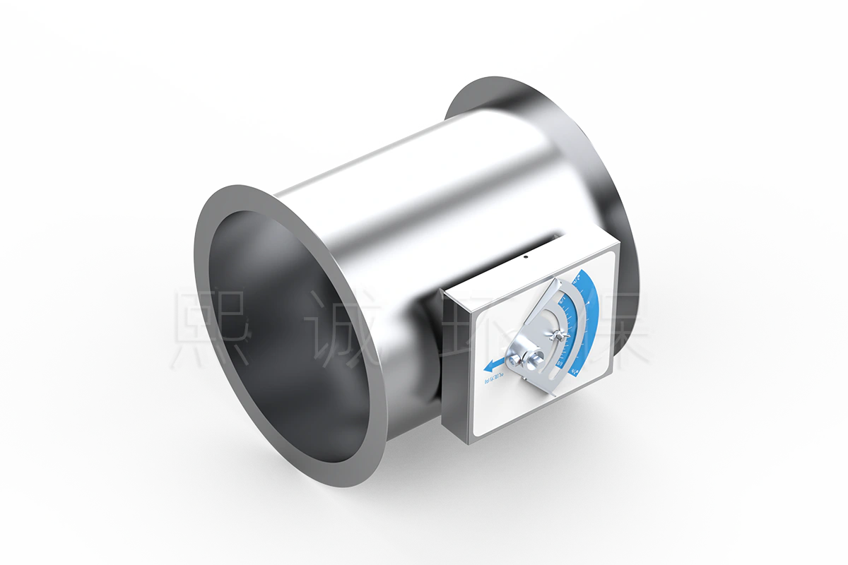
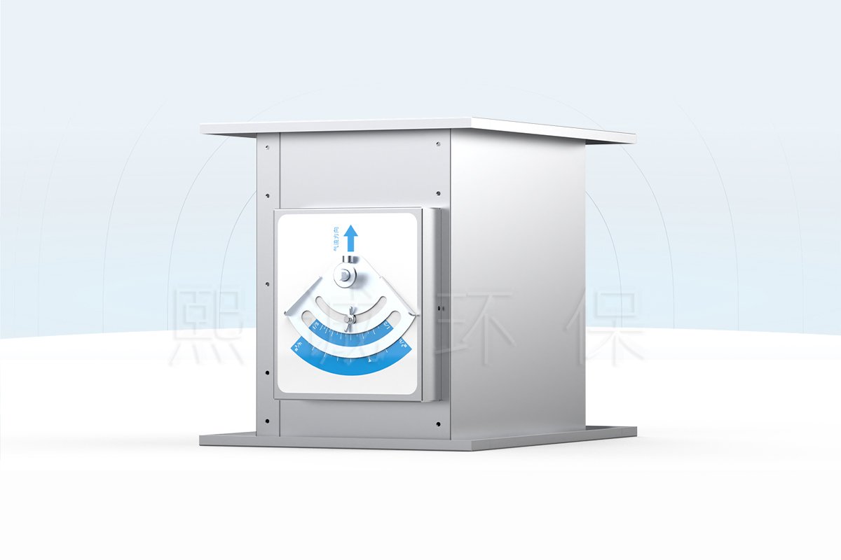
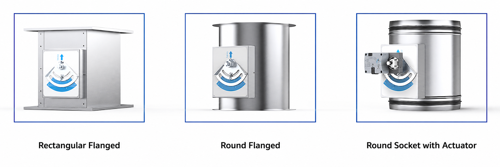
A constant airflow regulator is used when a supply or exhaust branch must maintain one fixed airflow setpoint while duct pressure varies. The basic regulating action is mechanical and requires no external electrical or pneumatic power. XICHENG supplies round and rectangular constructions so the regulator can match the actual duct geometry instead of forcing an unnecessary transition.
Choose This Product When
- The branch has one fixed design airflow during the operating mode covered by the regulator.
- The project can define the airflow setpoint, available pressure and duct size before ordering.
- A self-regulating CAV device is preferred over a sensor-controller-actuator loop.
- The installed pressure remains inside the selected regulator’s operating range.
- Factory setting and site airflow verification are included in commissioning.
Round or Rectangular Configuration
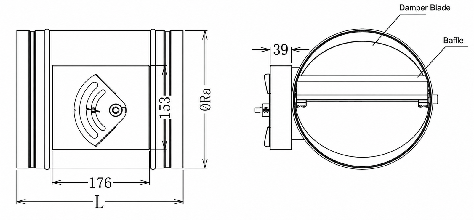
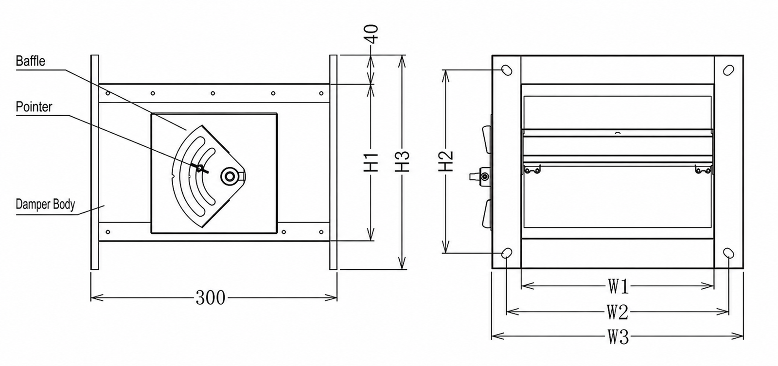
Round units are available for nominal sizes 100–400, while rectangular units use project-specific W × H openings and published airflow bands. The two forms share the CAV purpose but do not share dimensional tables. Choose the body form from the duct connection first, then confirm the airflow setpoint and pressure.
A round regulator is normally the direct choice for spiral or circular ductwork because it avoids a shape transition and keeps the adjustment mechanism compact. A rectangular regulator fits branches already scheduled by width and height and provides substantially higher listed airflow at the larger sizes. In either case, the regulator is ordered around a defined airflow, not selected from duct area alone.
What This Product Does Not Replace
This is not a continuously modulating VAV damper, fire damper, smoke damper, backdraft damper or certified isolation valve. When a branch needs two commanded airflow levels, use the two-position constant air volume damper. When airflow must follow a continuous control signal, use a VAV butterfly damper.
Key Specifications, Sizes and Airflow
Key selection data appears early because airflow, pressure and duct geometry determine whether the product belongs in the schedule. Values apply to the documented XICHENG mechanical family; the order confirmation assigns a specific configuration to each damper tag.
| Specification | Available Configuration | Selection Meaning |
|---|---|---|
| Product type | Mechanical constant airflow regulator | Maintains one factory-set airflow without an external power supply |
| Duct forms | Round and rectangular | Use the matching dimension and airflow table |
| Air-system duty | Supply or exhaust | Confirm air-stream chemistry and temperature |
| Operating temperature | 10–50°C | Applies to the documented mechanical family |
| Differential-pressure range | 50–1000 Pa | The selected airflow must be checked within this range |
| Body materials | Galvanized steel or 304 stainless steel | Final material is project selected |
| Standard plate thickness | 1.2 mm | Other thicknesses can be customized |
| Connections | Flange; custom socket connection | Match the project duct detail |
| Inlet requirement | At least 1.5D straight duct | Preserves a stable inlet velocity profile |
Round CAV Dimensions
| Nominal Size | Inside Diameter | Body Length L |
|---|---|---|
| 100 | 99 mm | 300 mm |
| 125 | 124 mm | 300 mm |
| 160 | 159 mm | 300 mm |
| 200 | 199 mm | 300 mm |
| 250 | 249 mm | 300 mm |
| 300 | 299 mm | 300 mm |
| 315 | 314 mm | 300 mm |
| 400 | 399 mm | 300 mm |
The listed inside diameters are 99, 124, 159, 199, 249, 299, 314 and 399 mm for nominal sizes 100 through 400. Check the connection style and external envelope on the approved drawing before fabrication.
Rectangular CAV Airflow Bands
| Rectangular Size | Qmin | Qmax | Listed Deviation | Minimum Total Pressure Difference |
|---|---|---|---|---|
| 200 × 100 mm | 144 m³/h | 504 m³/h | ±10% | 60 Pa |
| 300 × 100 mm | 216 m³/h | 756 m³/h | ±10% | 60 Pa |
| 300 × 200 mm | 432 m³/h | 1,512 m³/h | ±10% | 60 Pa |
| 400 × 200 mm | 576 m³/h | 2,016 m³/h | ±10% | 60 Pa |
| 400 × 250 mm | 720 m³/h | 2,520 m³/h | ±10% | 60 Pa |
| 500 × 250 mm | 900 m³/h | 3,150 m³/h | ±10% | 60 Pa |
| 500 × 300 mm | 1,080 m³/h | 3,780 m³/h | ±10% | 60 Pa |
| 500 × 500 mm | 1,800 m³/h | 6,300 m³/h | ±10% | 60 Pa |
| 600 × 400 mm | 1,728 m³/h | 6,048 m³/h | ±10% | 60 Pa |
| 600 × 600 mm | 2,592 m³/h | 9,072 m³/h | ±10% | 60 Pa |
Read Qmin and Qmax by row. Do not combine the minimum from one body size with the maximum from another. The listed 60 Pa value is the minimum total pressure difference for the rectangular table, while 50–1000 Pa is the broader documented family operating range.
How the Mechanical Constant Airflow Regulator Works
Airflow force moves the blade toward the closed direction as duct pressure rises. An inflatable air bag amplifies and damps that force, while a spring plate and shaped cam apply counterforce in the opposite direction. The balance between these forces changes the free area so airflow remains near the selected setpoint within the applicable pressure range.
Blade and Air-Bag Response
The blade must move freely. The air bag is both a force-transfer and damping component, reducing abrupt movement as pressure changes. Dirt, mechanical damage or an obstructed blade can alter the response and should be checked during service.
Spring and Cam Counterforce
The spring/cam mechanism is characterized around the selected airflow range. Moving the setting pointer after factory calibration changes the intended setpoint. Any field adjustment should be followed by measured airflow verification.
Pressure Independence Has Limits
Mechanical regulation is effective only inside the documented pressure and airflow envelope and with a stable inlet profile. It does not create fan capacity, correct severe duct turbulence or prove room pressure performance by itself.
Pressure independence also does not mean zero pressure loss. The regulator deliberately changes its throttling effect as available pressure changes. The fan calculation must include the pressure needed by the regulator at the selected airflow together with filters, coils, duct, terminals and other components in the branch.
Materials, Construction and Connections
Galvanized Steel
Galvanized steel is the standard option for normal supply and exhaust duties. Confirm whether coating, insulation or additional protection is required for the external environment.
304 Stainless Steel
304 stainless steel can be selected where cleaning, durability or moderate corrosion resistance is required. Chemical exhaust selection must still review every exposed component and the actual concentration and temperature.
Flange and Socket Connections
Flanged construction supports bolted duct coordination. A custom socket connection is available where a slip-fit arrangement is preferred. Seal material and fastening method must preserve air tightness.
Applications and Detailed Selection
Typical uses include laboratory supply air, general exhaust, cleanroom support branches, pharmaceutical ventilation and commercial HVAC zones with one fixed design airflow. The regulator can reduce repeated manual balancing when pressure changes elsewhere in the system, but the branch still requires measured acceptance.
Selection Sequence
- Define the fixed design airflow for each tag.
- Confirm available differential pressure at minimum and maximum fan conditions.
- Select round or rectangular geometry and the applicable row.
- Choose body material and connection.
- Review temperature, chemistry, orientation and straight-run space.
- Approve the factory setting and site verification method.
Information Required for a Quotation
Provide airflow, duct size, supply or exhaust duty, operating pressure, temperature, chemistry, material, connection, orientation, quantity and destination. Include the duct layout where a bend, transition or branch is close to the inlet.
When to Select Another Airflow Device
Use the two-position CAV damper for two commanded fixed airflows. Use a VAV Venturi air valve when the specified mechanism requires pressure-compensated variable airflow, or a duct airflow control damper for a sensor-based modulating loop.
Installation, Commissioning and Maintenance
Inlet Airflow Condition
Provide at least 1.5D of straight duct before the inlet and more space when a transition or strong disturbance would prevent a stable velocity profile. Install in the marked airflow direction and preserve access to the setting mechanism.
Flanged Installation
Use compressible sealing material between flanges, align the body without distortion and support adjacent ductwork independently. Uneven bolt loading can twist the frame and restrict blade movement.
Socket Installation
Deburr and clean the duct, insert it to the intended stop and seal the full circumference. Use evenly spaced self-tapping fasteners where specified without interfering with the blade or internal mechanism.
Airflow Acceptance
Measure airflow at the intended operating condition and record the result by tag. Do not rotate the setting plate after calibration unless the new setting is measured and documented. Check multiple fan conditions to confirm that the regulator remains inside its operating pressure envelope.
Acceptance should distinguish the ordered airflow value, measured airflow, measurement uncertainty and available pressure. If the result is outside the specified tolerance, first check the inlet profile, duct leakage, instrument location and actual pressure before changing the calibrated setting. This prevents a site adjustment from masking a system-layout problem.
Maintenance
Inspect for contamination, damaged seals, restricted blade movement and altered settings. The basic mechanism is low maintenance, but it is not immune to buildup or mechanical damage in an exhaust stream.
Related Constant and Variable Airflow Products
Compare the Two-Position Constant Air Volume Damper, Constant Volume Venturi Air Valve, Round VAV Butterfly Damper and Rectangular VAV Butterfly Damper. Browse the Laboratory Air Dampers category.
Frequently Asked Questions
Does the Regulator Need Electrical Power?
No. The basic CAV mechanism is self-regulating and operates without external power.
What Pressure Range Is Documented?
The documented family range is 50–1000 Pa. The rectangular airflow table separately lists a 60 Pa minimum total pressure difference.
Are Round and Rectangular Sizes Available?
Yes. Round nominal sizes 100–400 and multiple rectangular W × H configurations are documented.
Can It Be Used for Exhaust Air?
Yes, subject to material and component compatibility with the actual air stream.
Can the Airflow Be Changed on Site?
The setting can be adjusted, but a changed setting must be verified by airflow measurement. Factory setting is preferred for repeatable delivery.
What Straight Duct Is Required?
Provide at least 1.5D at the inlet and increase the distance where upstream disturbances are severe.
Contact the Xicheng Engineering Team Today
Send the duct size, airflow schedule, operating pressure, air-stream conditions, control requirement and quantity. XICHENG will return a project-specific configuration, technical schedule and quotation.
Shenzhen Office: No. 34 Zhenxing Road (Shengtaian Heavy Industrial Park B), Loucun, Guangming New Dist, Shenzhen, Guangdong, China
WhatsApp: +86 18126478161
Engineering Mailbox: fanalax34@gmail.com