


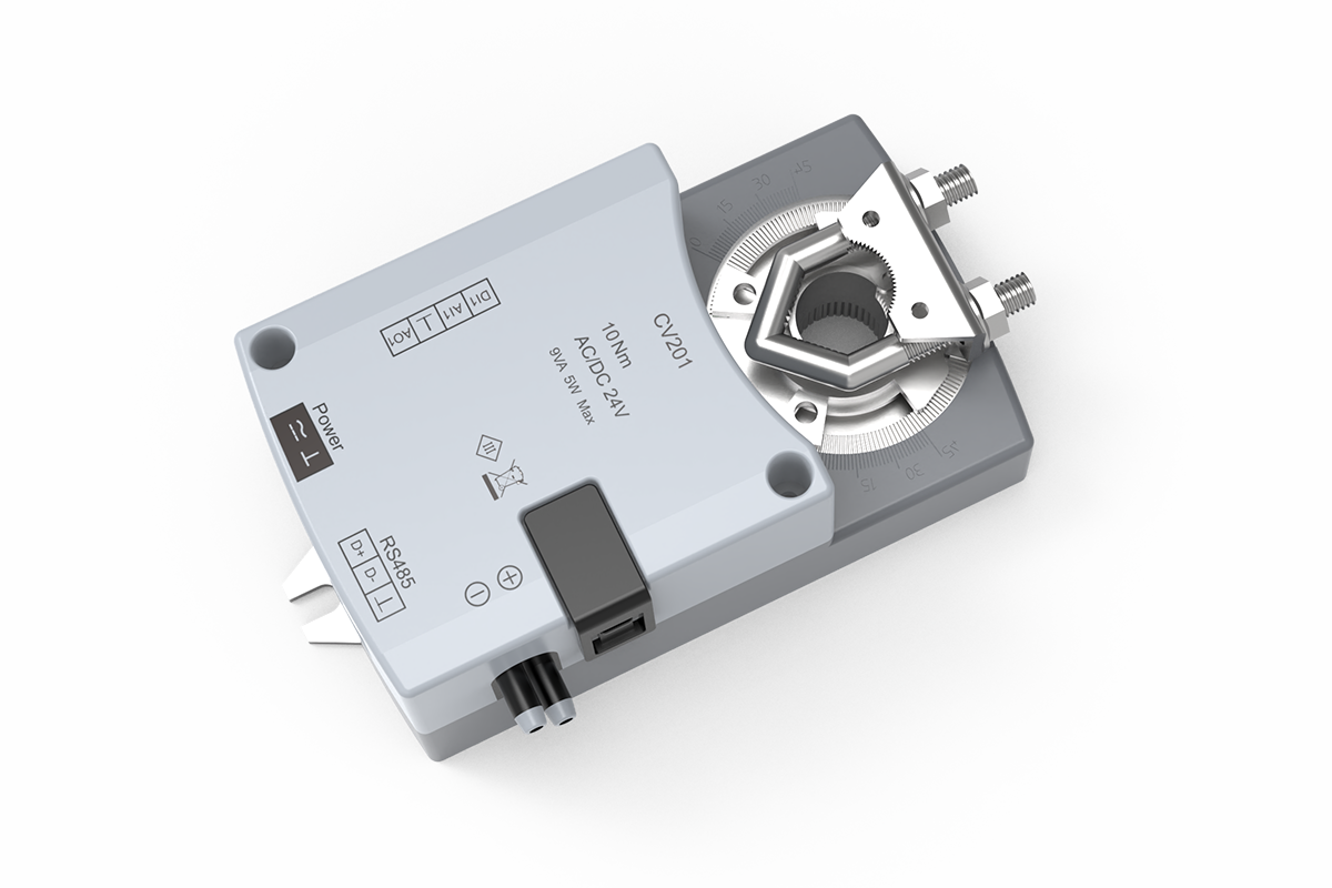
Description
This integrated VAV controller combines differential-pressure airflow measurement, control logic, and a rotary damper actuator for laboratory supply, exhaust, and area-pressure branches. It is part of XICHENG’s laboratory airflow controls and actuators range and is selected where one field-mounted assembly must regulate a compatible air damper from measured airflow or a project-defined pressure sequence.
- Integrated 10 Nm rotary actuator with a 60-second 0-90-degree travel reference
- 8-15 mm shaft interface with at least 35 mm of usable engagement
- Analog airflow or pressure input, measured-airflow output, and dry-contact door input
- RS-485 communication with verified Modbus RTU support
The controller-actuator is not a complete damper, VAV terminal, airflow pickup, room supervisory controller, or fume hood safety system. The delivered configuration depends on the approved damper mechanics, measurement coefficient, control sequence, electrical interfaces, and commissioning method.
How the Integrated VAV Controller Regulates Airflow and Area Pressure
A variable air volume controller does not control airflow from shaft position alone. The useful loop starts with a pressure signal generated by an approved airflow pickup or pressure sensor. The controller interprets that signal according to the configured coefficient and demand, then drives the integrated rotary actuator. The damper changes branch resistance, the measured condition changes, and the controller continues correcting the output until the active control objective is reached within the engineered system.
Airflow-Control Path
For airflow control, the active demand may come from an analog command or a supervisory sequence. Differential pressure from the airflow pickup is converted into a measured airflow value using the configured device relationship. The controller compares demand with measurement, rotates the connected damper, and provides an airflow-feedback signal for monitoring or coordination. Minimum and maximum airflow limits, command scaling, coefficient, loop tuning and alarm behavior belong in the approved sequence.
Pressure-independent control means the controller is intended to correct damper position as available duct pressure changes, within the usable measurement and mechanical range of the completed assembly. It does not mean that any damper, pickup or installation will deliver the same airflow without engineering. The airflow device must still have enough available pressure, a stable measurement signal, suitable authority and a commissioned relationship between differential pressure and airflow.
Area-Pressure Participation
For an area-pressure application, a separate pressure input can represent the controlled room or zone condition. A dry-contact door input can participate in a defined door-open or door-closed sequence. The controller then adjusts the connected supply or exhaust damper according to the approved pressure objective and operating mode. The control narrative must identify whether pressure demand overrides, resets or limits airflow demand; no universal priority should be assumed.
A complete laboratory pressure strategy can require more than one branch, separate supply and exhaust measurement, door-state logic, fan coordination, alarm delays, occupied and unoccupied modes, emergency behavior and supervisory tracking. This device can own one assigned control task inside that system. It should not be specified as the entire room-pressure solution unless the project documents clearly show that one integrated controller-actuator can execute the complete required sequence.
Integrated Actuator Architecture
The controller and 10 Nm rotary actuator share one field assembly. This reduces the separate command, feedback and mounting interfaces that would exist between a standalone controller and an external actuator. The architecture is useful when the damper shaft and required torque fit the integrated mechanism and a 60-second travel reference is compatible with system dynamics. It is not automatically the right choice for fast emergency exhaust, high-torque dampers, linear mechanisms or projects with a separately specified fail-safe actuator.
The actuator’s hardware position feedback confirms mechanical movement, while measured airflow confirms the ventilation result. These are different signals. A correct position with an incorrect airflow value may indicate a pickup, coefficient, tubing, balancing, fan or duct-pressure problem. A correct airflow value with unexpected room pressure may indicate another branch, door condition, building pressure or supervisory-sequence issue.
What the Controller Does Not Replace
The supplied controller-actuator does not by itself define the damper body, airflow pickup, room-pressure sensor, transformer, control panel, tubing, fan, network controller, programming by others or TAB scope. It also does not add fire/smoke certification, chemical resistance, leakage performance or isolation duty to the selected damper. Each of those items must be identified in the valve-tag schedule and approved drawings.
For laboratory exhaust, review the air-stream chemistry and the exposed damper components independently from the controller enclosure. For fume hood service, use a dedicated fume hood controller when face velocity, sash position, hood alarm or automatic sash movement defines the safety task. This product remains an airflow/pressure controller even when its damper serves a hood exhaust branch.
VAV Controller Selection Summary
Choose this integrated airflow and pressure controller after defining both the control objective and the mechanical architecture. A branch may be described as VAV, pressure-controlled, supply-tracking, or laboratory exhaust, but those labels alone do not identify the active input, required response, actuator output, or acceptance test. Start with the variable the controller needs to maintain and the field measurement that will verify performance.
Select by the Primary Controlled Variable
Choose airflow control when minimum, normal, maximum or emergency airflow is the primary acceptance value and a suitable differential-pressure measurement can be commissioned. Choose area-pressure participation when an approved pressure sensor and control sequence define how the branch responds to the controlled room or zone. If both objectives are required, the design must state which loop is primary, how the second loop resets or limits demand, what happens when a door opens, and how transitions avoid unstable damper movement.
Select by Actuator Architecture
This product is a strong candidate when a 10 Nm integrated rotary actuator and 60-second travel suit the damper and the control sequence. Choose the duct airflow controller with integrated fast VAV actuator when the verified fast rotary or linear configurations of that product match a branch that requires materially faster motion. Choose the duct airflow and pressure controller for an external actuator when torque, thrust, travel, fail-safe behavior, remote mounting, retrofit conditions or the valve supplier require a separately selected actuator.
The presence of an actuator in each architecture does not make the products interchangeable. Compare controlled variable, measurement method, actuator motion, torque or thrust, travel time, shaft/linkage, signal ownership, local functions, fail behavior, communication and supplied scope. Use the product whose verified hardware and sequence match the tag rather than choosing by model order.
Confirm the Mechanical Fit Before Electrical Design
Confirm damper torque under the actual pressure condition, shaft diameter, usable shaft length, rotation, clamp position, anti-rotation support, service clearance and manual-release access. The 8-15 mm shaft range and 35 mm minimum engagement provide an initial interface check. They do not establish that the blade can close, modulate and reopen through its full operating range under load.
Where the design uses a VAV butterfly damper, approve blade geometry, material, seals, leakage requirement, shaft and torque together with the controller-actuator. A VAV Venturi air valve normally uses a different control mechanism and verified size/flow relationship; do not assume this rotary integrated actuator can replace the valve’s specified actuator or cone linkage.
Confirm the Control and Communication Revision
Define the analog input range and scaling, airflow-feedback output, door-contact behavior, pressure-sensor range, setpoint source, network address, baud rate, Modbus register map, command permissions, and communication-loss state. For DC-powered installations, confirm the selected hardware revision because the technical data contains both 24 VDC +/-10% and 24-36 VDC references. Modbus RTU is confirmed; BACnet MS/TP is not included unless the selected version has a separate verified protocol declaration.
Choose A Different Control Architecture When
- The damper requires more torque, a different shaft interface, linear movement, spring return or another certified fail-safe function.
- The required motion is materially faster than a 60-second 0-90-degree actuator reference.
- The project cannot provide a suitable airflow pickup, pressure signal, coefficient, balancing method or acceptance measurement.
- The primary task is face-velocity monitoring, sash-position control, automatic sash movement, fire/smoke control or certified isolation.
- A complete terminal unit, valve body or room supervisory controller is required as a single listed package and the quotation does not include that scope.
Resolve these conditions before adding the controller to the valve schedule. A complete quotation identifies the mechanical, electrical, control, and commissioning configuration for each tag instead of relying on a generic controller designation.
Key VAV Controller Specifications
Verified Controller and Actuator Data
The following values describe the integrated controller-actuator configuration. The damper body, airflow pickup, tubing, room-pressure sensor, transformer, local interface and BMS engineering are separate unless the approved quotation names them.
| Specification | Product Data |
|---|---|
| Product architecture | Integrated airflow/pressure controller, differential-pressure airflow sensing and rotary damper actuator |
| Primary control functions | Variable airflow control and project-defined area/room differential-pressure control |
| Airflow sensing | Built-in differential-pressure airflow sensing |
| Analog input | One input for airflow or pressure demand/input; confirm signal range and scaling |
| Analog output | One measured-airflow feedback output; confirm signal range and scaling |
| Dry-contact input | One door-contact / magnetic-switch input for a configured pressure sequence |
| Communication | RS-485 with Modbus RTU support |
| Actuator type | Integrated rotary damper actuator with manual release |
| Rated actuator output | 10 Nm |
| Travel reference | 60 seconds for 0-90 degrees |
| Shaft diameter | 8-15 mm |
| Minimum shaft engagement | 35 mm |
| Damper-area reference | Up to 0.5 m2 in the referenced configuration; final torque/load approval is required |
| Controller dimensions | 130.0 x 69.0 x 56.0 mm |
| Operating environment | 0 to +50 C; 10-95% RH, non-condensing |
| Storage environment | -20 to +50 C; 10-95% RH, non-condensing |
| AC power reference | 24 VAC +/-10%, 50-60 Hz; 9 VA maximum |
| DC power reference | 5 W maximum; confirm the supplied revision because 24 VDC +/-10% and 24-36 VDC both appear in the technical data |
How to Use the Numerical References
The actuator’s 10 Nm rating is a starting point for mechanical selection, not a statement that every damper up to the referenced area will move reliably. Calculate or obtain required torque at the maximum operating and close-off pressure, then account for blade seals, bearing friction, contamination, shaft alignment, linkage and an appropriate design margin. Confirm that the shaft and clamp remain accessible after duct insulation and adjacent services are installed.
The 60-second travel value describes actuator motion, not the response of the complete airflow or pressure loop. System response also depends on pickup dynamics, filtering, control tuning, damper authority, duct volume, fan response, sensor placement and supervisory commands. A project that requires a fast emergency transition should specify the total response objective and confirm that this actuator architecture can meet it.
The enclosure dimensions identify the controller body. Allow additional space for the shaft connection, anti-rotation support, wiring bend radius, pressure tubes, manual-release access, inspection and removal. The dimension drawing should be coordinated with the installed damper assembly instead of being treated as the complete installed envelope.
Power and Communication Revision Checks
For AC applications, the technical data identifies 24 VAC +/-10% at 50-60 Hz with a 9 VA maximum reference. For DC applications, the same data set includes both 24 VDC +/-10% and 24-36 VDC references together with a 5 W maximum reference. The approved submittal must identify the exact supplied revision, allowable input range, polarity, transformer/circuit sizing, grounding, protection and any shared-common restrictions.
Modbus RTU over RS-485 is the confirmed communication path. The wiring image also uses a `Modbus/MSTP` BMS label; that label should not be interpreted as verified BACnet MS/TP support without a current protocol declaration. Request the baud rate, parity, address range, register map, writable points, units, scaling, communication-loss behavior and network-bias/termination requirements for the supplied unit.
Fields That Remain Project-Specific
Airflow range, differential-pressure range, airflow accuracy, pressure accuracy, repeatability, minimum controllable airflow, total response, leakage, acoustic performance, enclosure protection, certifications and protocol registers are not defined by this product record. The selected damper provides its own size, material, pressure, leakage and chemical-compatibility data. The pickup and pressure sensor provide their own range, orientation and installation requirements.
Do not fill these fields with values from a different controller or valve configuration. Enter them only after the exact damper, measurement arrangement, controller revision and project sequence have been approved.
Airflow and Pressure Control Logic
The controller can participate in more than one ventilation objective, but each project must define one coherent sequence. The design should identify the source of demand, the measured variable, the output that moves the damper, the feedback returned to the BMS, and the behavior during sensor, network or power faults. Listing several available inputs without assigning ownership creates two controllers that may issue competing commands to the same branch.
Signal Ownership and Control Roles
| Signal or Function | Typical Role | Project Definition Required | Acceptance Evidence |
|---|---|---|---|
| Analog airflow/pressure input | Provides airflow demand or an external pressure-related input | Range, units, scaling, source, priority and fail value | Injected-value and end-to-end command test |
| Differential-pressure airflow sensing | Measures the pressure signal used to calculate branch airflow | Pickup, tubing, coefficient, filter and valid range | Comparison with calibrated field airflow measurement |
| Area-pressure sensor | Represents the controlled room or zone differential pressure | Range, reference location, polarity, target, deadband and delay | Door-state and disturbance-response test |
| Door dry contact | Indicates a door state to the configured pressure sequence | Normally open/closed logic, delay, override and recovery | Observed state change and commanded response |
| Integrated actuator | Rotates the damper in response to the active control output | Direction, limits, shaft, torque, fail state and manual release | Full powered stroke and mechanical inspection |
| Airflow feedback output | Returns measured airflow to a BMS or coordinating controller | Range, scaling, units, common and invalid-signal behavior | Point-to-point comparison with local measured value |
| Modbus RTU | Provides supervisory values, commands or status according to the approved map | Address, baud, parity, writable points, units and timeout | Network point list and loss-of-communication test |
Airflow-Control Sequence
In an airflow-control sequence, the controller receives or calculates an active airflow demand. Differential pressure from the pickup is converted to airflow using the configured relationship. The controller modulates the damper to reduce the difference between demand and measurement, while minimum and maximum limits prevent the branch from operating outside its approved range. The airflow-feedback output or network point allows another controller to monitor or track the result.
The coefficient must belong to the actual damper/pickup arrangement. Reusing a value from another valve size or installation can create a stable but incorrect displayed airflow. Tubing polarity, leaks, kinks, condensate, blocked ports and poor pickup location can produce similar errors. Commissioning must compare the controller’s measured value with an independent field measurement at more than one operating point.
Area-Pressure Sequence
Area-pressure control begins with the project target, pressure-sensor range and reference location. The controller can adjust its connected damper in response to that pressure input, while the door contact can identify a state transition. The sequence must state whether the branch controls supply or exhaust, the intended positive or negative relationship, the allowable pressure band, response delay, airflow limits and behavior when the door remains open.
Door-open response should not be invented at the product level. Some projects hold the last stable output, some move to a defined airflow, and others temporarily widen the pressure deadband to prevent hunting. The approved sequence should also define recovery after closure, alarm delay, occupied/unoccupied targets and interaction with other supply or exhaust devices.
Combined Airflow and Pressure Control
When both airflow and pressure matter, one loop normally provides the primary command and the other modifies or limits it. For example, a room-pressure controller may calculate an airflow demand while this device closes the branch airflow loop. In another arrangement, a local pressure input may reset the branch demand within approved airflow limits. Either approach can work, but the signal path must be explicit.
Avoid connecting independent analog and network commands without defined arbitration. State which command wins, how local/manual states are handled, what occurs after network loss, and whether the controller returns to a fixed airflow, last value or project-defined fail state. The supplied Modbus register map and control narrative must agree with the BMS database.
Position Is Diagnostic, Not the Controlled Result
The integrated actuator can provide hardware position information, but position is not a substitute for measured airflow or room pressure. Damper position may help identify a saturated branch, insufficient fan pressure, blocked pickup, mechanical binding or incorrect rotation. Acceptance should therefore record command, position, measured airflow, area pressure and relevant fan/door state at the same time.
This distinction also supports maintenance. A gradual increase in required opening at the same airflow may indicate changes in system resistance, while a fixed position with changing measured airflow may indicate fan or pressure variation. Trend interpretation is useful only after the signals have been scaled and commissioned correctly.
Integrated Damper actuator and Mechanical Fit
The integrated rotary actuator converts the controller output into damper movement. Its verified 10 Nm output and 60-second 0-90-degree travel reference define the starting mechanical envelope. Final selection still depends on the damper’s torque curve, shaft geometry, pressure load, required close-off behavior and service conditions.
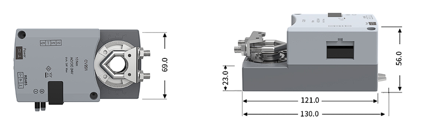
Mechanical Interface Checklist
| Mechanical Item | Product Reference | Project Check | Acceptance Evidence |
|---|---|---|---|
| Rotary output | 10 Nm | Required running and close-off torque with design margin | Approved damper torque data and powered stroke |
| Travel | 0-90 degrees in 60 seconds | Required angle, end stops and sequence response | Timed full-stroke and command test |
| Shaft diameter | 8-15 mm | Actual shape, diameter, clamp contact and concentricity | Measured shaft and installed clamp inspection |
| Shaft engagement | 35 mm minimum | Usable length after bracket, insulation and clearance | Installation drawing and site measurement |
| Damper area | 0.5 m2 reference configuration | Blade geometry, pressure, seals, bearings and contamination | Tag-specific load approval; area alone is insufficient |
| Manual release | Integrated release for manual positioning | Safe access and maintenance procedure | Release/re-engagement check before powered operation |
| Body envelope | 130.0 x 69.0 x 56.0 mm | Wiring, tubing, inspection and removal clearances | Coordinated layout or shop drawing |
Torque Must Be Checked at the Damper
Nominal damper area does not predict torque reliably across different blade designs. A low-leakage butterfly damper with tight seals can require more torque than a larger, lightly loaded balancing damper. Pressure differential, shaft diameter, bearing friction, blade offset, corrosion, deposits and temperature also change the required output. Obtain the damper manufacturer’s torque requirement or test the actual assembly under the design condition.
Where chemical exhaust is involved, review the body, blade, shaft, seals and exposed fasteners for the air stream. Material compatibility belongs to the damper schedule; the controller-actuator does not make an incompatible damper chemically resistant.
Shaft, Rotation and Mounting
Confirm shaft shape as well as diameter. Verify that the clamp can seat without damaging the shaft, that the actuator and blade rotate in the intended direction, and that mechanical end stops do not force the motor to stall. An anti-rotation support should prevent the enclosure from moving while avoiding housing distortion. Mounting must preserve access to the manual release, terminals and pressure connections.
Before energizing, move the damper through its safe range using the approved manual procedure. Check for binding, seal interference and linkage play. Re-engage the actuator fully, verify the controller’s direction setting and perform a powered stroke. Record the commanded position, observed blade position and final airflow response separately.
When an External Actuator Is the Better Choice
Use a split controller and external actuator when the project requires higher torque, spring return, a certified fail-safe function, linear motion, remote mounting, a different travel time or a valve-specific actuator. The external-actuator airflow and pressure controller keeps sensing and control separate from the mechanical drive. If fast integrated rotary or linear motion is required and its verified mechanical range fits, compare the fast integrated duct airflow controller.
Airflow Measurement and System Compatibility
The built-in sensor receives a differential-pressure signal; it does not create a complete airflow measurement by itself. The installed pickup, tubing, coefficient and controller must describe the same airflow device. Their compatibility determines whether the displayed value can be used for control and acceptance.
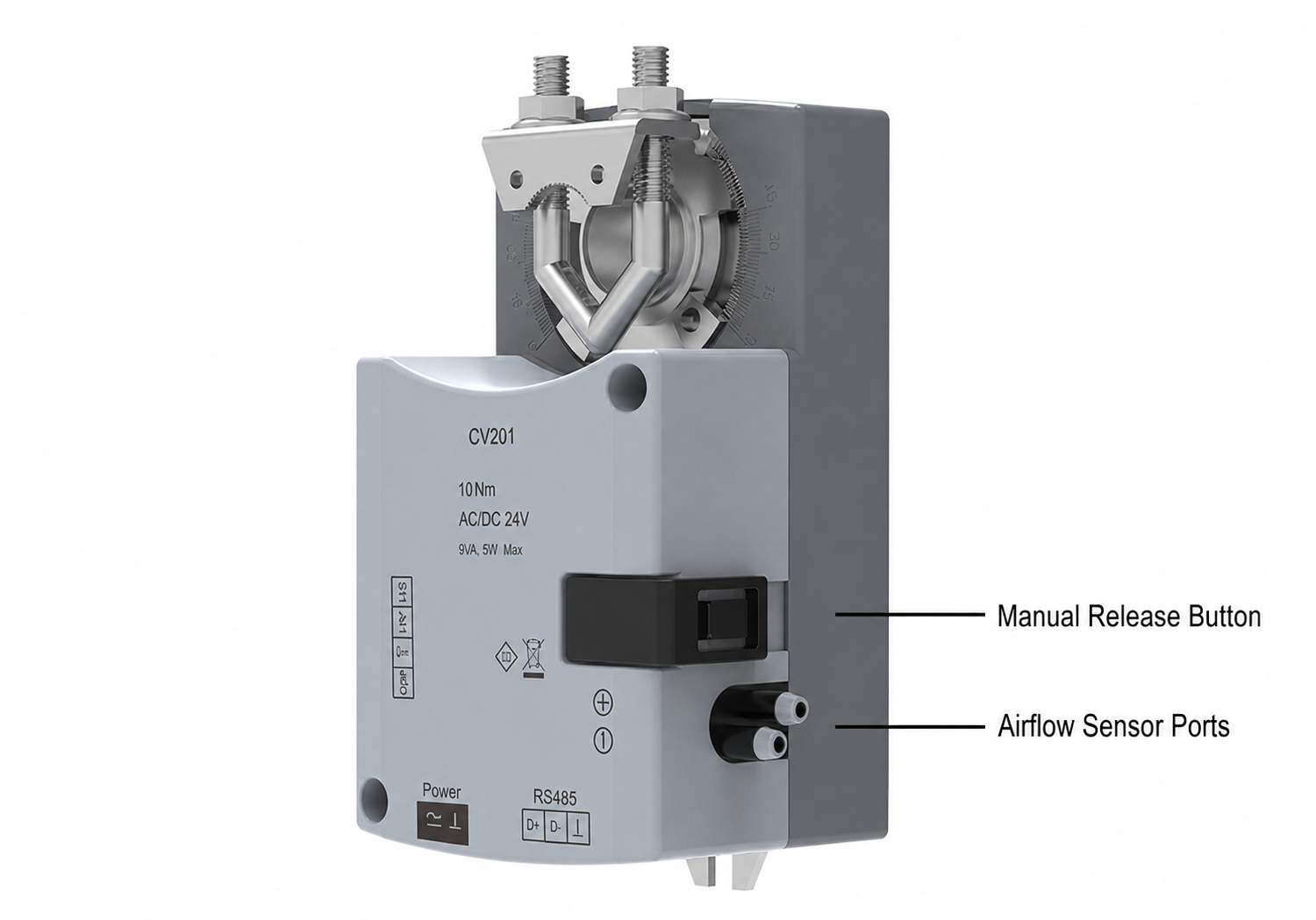
Airflow Pickup and Tubing
Select a pickup that provides a stable differential-pressure signal across the required airflow states. Mount it in the orientation and duct location used to establish its airflow relationship. Keep high- and low-pressure tubes correctly identified, short where practical, protected from kinks and abrasion, and free from leaks, blockage or condensate. Route tubing so service work cannot reverse the ports.
Coefficient and Field Balancing
The configured coefficient must match the actual pickup, valve size and installation. During commissioning, compare controller airflow with a calibrated field method at minimum, normal and maximum states. If the error changes across the range, inspect the pickup and flow profile before applying a single offset. Record the final coefficient and units in the tag schedule and controller backup.
Pressure-Control Compatibility
An area-pressure sequence also needs an approved pressure sensor and reference point. Confirm range, polarity, reference location, tubing, response filtering and mounting. The pressure sensor should resolve the intended target without saturating during door movement or fan transitions. Its signal must be mapped to the controller input with the same units and polarity used in the control narrative.
For multi-branch laboratories, coordinate this controller with the room supervisory logic, supply/exhaust tracking and fan system. The laboratory airflow control category provides related damper and valve mechanisms, but each device still requires its own approved measurement and mechanical data.
Applications and Project Fit
Laboratory Supply and General Exhaust
The controller can regulate a supply or exhaust branch when the selected damper, pickup and available pressure support the scheduled airflow range. For room-pressure participation, define whether the controlled branch adds supply or removes exhaust, how its demand is limited, and how it coordinates with the opposite air path. Verify both airflow and room response during occupied, unoccupied and door-transition conditions.
Fume Hood Exhaust Branches
A fume hood exhaust damper may use this product when another approved device or sequence provides the required airflow/pressure demand and the 10 Nm, 60-second rotary architecture fits the branch. The controller does not replace direct face-velocity monitoring, sash-position demand, hood alarms or automatic sash operation. Select the relevant fume hood controller when those hood-specific functions define the product.
Equipment Ventilation and Retrofit Work
Equipment exhaust and retrofit branches can use the integrated controller when the existing damper shaft, torque and pickup can be verified. Survey available shaft length, rotation, service clearance, wiring, pressure tubes and BMS interface before specifying a direct replacement. If the existing actuator must remain, use the external-actuator airflow controller instead of forcing an integrated conversion.
Applications Requiring Another Product
Do not use this controller for fire/smoke control, certified isolation, liquid service, fan motor starting or safety-PLC duties. Use a dedicated damper actuator when the task is only to move a damper and measured airflow/pressure logic is unnecessary. Use a faster integrated controller when verified response is the primary requirement, and use a dedicated room controller when one device must coordinate multiple branches and room modes.
Installation, Wiring and Commissioning
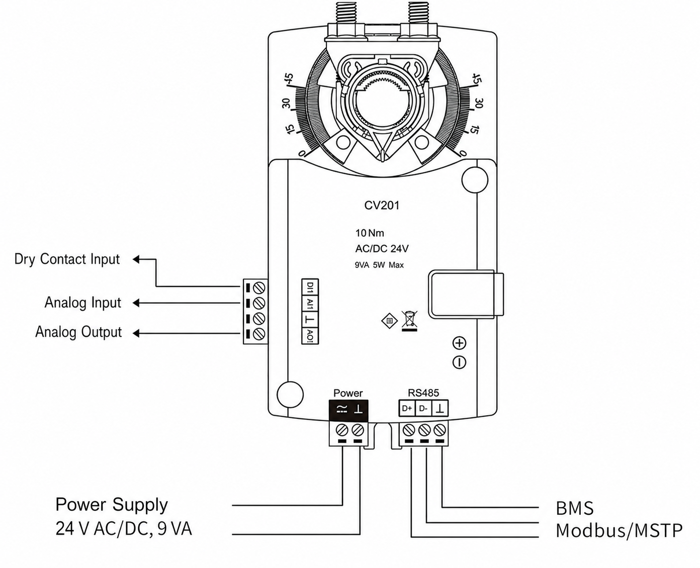
Interface Schedule
| Interface | Project Definition | Commissioning Check |
|---|---|---|
| Low-voltage power | Approved AC/DC revision, voltage range, polarity/common, protection and transformer scope | Measure voltage at the controller during actuator travel |
| Dry-contact input | Door device, normal state, delay, override, alarm and recovery sequence | Operate the contact and verify state, response and recovery |
| Analog input | Airflow or pressure source, range, units, scaling, polarity and fail value | Inject low/mid/high values and confirm controller interpretation |
| Analog output | Measured-airflow range, units, scaling, common and receiving point | Compare output/BMS value with controller and field measurement |
| RS-485 / Modbus RTU | Address, baud, parity, wiring polarity, termination, point map and timeout behavior | Read required points, test approved commands and simulate communication loss |
| Pressure ports | Pickup, high/low tubing, coefficient, routing and condensate protection | Leak/polarity check and multi-point airflow comparison |
| Rotary actuator | Shaft, direction, travel limits, torque, fail state and manual-release access | Manual inspection, powered full stroke and mechanical-position check |
Installation Sequence
Mount and inspect the damper before final controller setup. Verify free blade movement, shaft engagement, clamp alignment and anti-rotation support. Install the airflow pickup and pressure tubes with correct polarity. Complete low-voltage and signal wiring from the current terminal schedule, then confirm power and commons before enabling the actuator.
Configuration and Network Setup
Enter the airflow relationship, limits, input/output scaling, pressure target, door sequence, actuator direction and fail behavior from the approved control narrative. Configure Modbus RTU address and serial settings, then verify the point list end to end. Because the wiring artwork uses a `Modbus/MSTP` label, do not commission BACnet MS/TP unless the supplied revision includes a separate verified protocol declaration.
Functional Acceptance
Prove damper travel first, then prove measured airflow at multiple setpoints. Test area-pressure behavior at stable and disturbed conditions, including the defined door event. Verify analog feedback, network values, alarms, power recovery and communication-loss behavior. Record controller revision, coefficient, final settings, measured results, unresolved deviations and as-built drawings for handover.
Selection and Specification Requirements
A project specification should identify this product as an integrated variable air volume controller with differential-pressure airflow sensing and a 10 Nm rotary damper actuator. State whether the assigned loop controls branch airflow, participates in area-pressure control, or accepts a calculated demand from another controller. Define the analog input and feedback, door contact, Modbus RTU interface, actuator rotation, shaft, power revision and loss-of-signal behavior.
The valve-tag schedule should include damper type and material, size, shaft geometry, torque, airflow states, available pressure, pickup and coefficient, area-pressure sensor and target, sequence priority, response requirement, wiring responsibility, network points, fail state and acceptance tests. Mark the damper body, pickup, tubing, pressure sensor, transformer, BMS programming and TAB work as supplied or by others.
Require an approved submittal before fabrication or site wiring. The submittal should resolve the DC input range and protocol revision, confirm the mechanical interface, and identify every contractual value that is not established by the family-level data.
Technical Data, Configuration, And Documentation
Coordinate the current controller-actuator datasheet, dimension drawing, terminal schedule, Modbus register map, damper drawing, torque data, airflow-pickup data, pressure-sensor data, valve-tag schedule, and control sequence. The revision shown on the power and communication documents needs to match the selected unit.
For commissioning, record the final coefficient, input/output scaling, network settings, actuator direction, airflow limits, pressure targets, door sequence, alarm and failure behavior, and point-to-point results. Retain measured airflow and pressure results, powered-stroke evidence, configuration backups, and as-built drawings for future troubleshooting or replacement.
The product data sheet defines the available controller functions, while the tag schedule and final drawings define the installed configuration. When a required value is not available, confirm it for the selected unit instead of importing a value from another controller family.
Related Airflow Controllers, Dampers and Fume Hood Controls
Choose the duct airflow controller with integrated fast VAV actuator when verified fast rotary or linear motion is more important than this product’s 10 Nm, 60-second rotary architecture. Choose the duct airflow and pressure controller for an external actuator when the valve supplier, retrofit condition, required torque, fail-safe function or mounting arrangement requires a separate drive.
Pair this controller with a compatible VAV butterfly damper only after shaft, torque, rotation, material, seals, pressure, leakage and airflow-measurement data are approved together. Evaluate a VAV Venturi air valve separately because its mechanism, airflow relationship and actuator interface are not interchangeable with a rotary butterfly damper.
For a laboratory hood, use the fume hood controller with integrated VAV actuator, fume hood face-velocity controller, sash-position fume hood controller or automatic sash fume hood controller when hood-specific sensing, alarms or sash operation defines the task. Compare products by controlled variable, sensor, actuator architecture, response, I/O, safety scope and acceptance method.
Frequently Asked Questions
What does this VAV controller control?
It can control branch airflow from a differential-pressure airflow signal and can participate in a project-defined area or room differential-pressure sequence. The active demand, sensor, limits, priority and fail behavior must be defined in the control narrative. It is not a complete room-control system by itself.
Does the controller include a damper actuator?
Yes. The assembly includes an integrated 10 Nm rotary actuator with a 60-second 0-90-degree travel reference. The damper body is separate unless the quotation names a combined assembly. Confirm shaft diameter, engagement, torque, rotation, pressure load and service clearance for every tag.
What damper shaft fits the integrated actuator?
The verified reference is an 8-15 mm shaft diameter with at least 35 mm of usable engagement. Shaft shape, clamp contact, anti-rotation support and access must also be approved. A shaft that fits dimensionally can still be unsuitable if the required damper torque exceeds the actuator output.
Is the 0.5 m2 damper reference a guaranteed maximum size?
No. It is a configuration reference, not an unconditional sizing rule. Damper torque depends on blade design, seals, bearings, shaft, pressure differential, deposits and required close-off behavior. Approve the actual torque demand with a design margin.
Does actuator position prove airflow?
No. Position confirms mechanical movement, while airflow requires an approved pickup, correct tubing polarity, the matching coefficient and field measurement. Commission minimum, normal and maximum airflow and compare controller feedback with an independent calibrated method.
Can it control a fume hood exhaust damper?
It can regulate the exhaust branch when the project supplies an approved airflow or pressure demand and the integrated actuator fits the damper. Direct face velocity, sash demand, hood alarm and automatic sash control require the appropriate fume hood control product.
Which power supply and BMS protocol should be specified?
The product data identifies 24 VAC +/-10% and includes two DC references: 24 VDC +/-10% and 24-36 VDC. Confirm the supplied revision for DC projects. Modbus RTU over RS-485 is confirmed; do not specify BACnet MS/TP unless the supplied version has a separate verified protocol declaration.
What should be submitted for quotation?
Provide the airflow states, pressure target and sequence, damper and shaft data, torque, pickup and coefficient, available pressure, sensor range, door logic, analog signals, feedback destination, power, Modbus points, failure state, quantity, drawings, and destination. XICHENG will use these details to recommend the controller revision and provide the applicable interfaces, included components, documentation, commissioning requirements, and price.
Contact the Xicheng Engineering Team Today
Send the damper and shaft drawing, torque data, airflow schedule, area-pressure sequence, pickup and sensor information, power supply, I/O schedule, Modbus requirements, quantity, and installation drawings. XICHENG will recommend an integrated VAV controller-actuator configuration and provide the applicable technical details and quotation within 24 hours.
Shenzhen Office: No. 34 Zhenxing Road (Shengtaian Heavy Industrial Park B), Loucun, Guangming New Dist, Shenzhen, Guangdong, China
WhatsApp: +86 181 2647 8161
Engineering Mailbox: fanalax34@gmail.com