


Description
VAV Air Damper for Classified Ventilation Areas
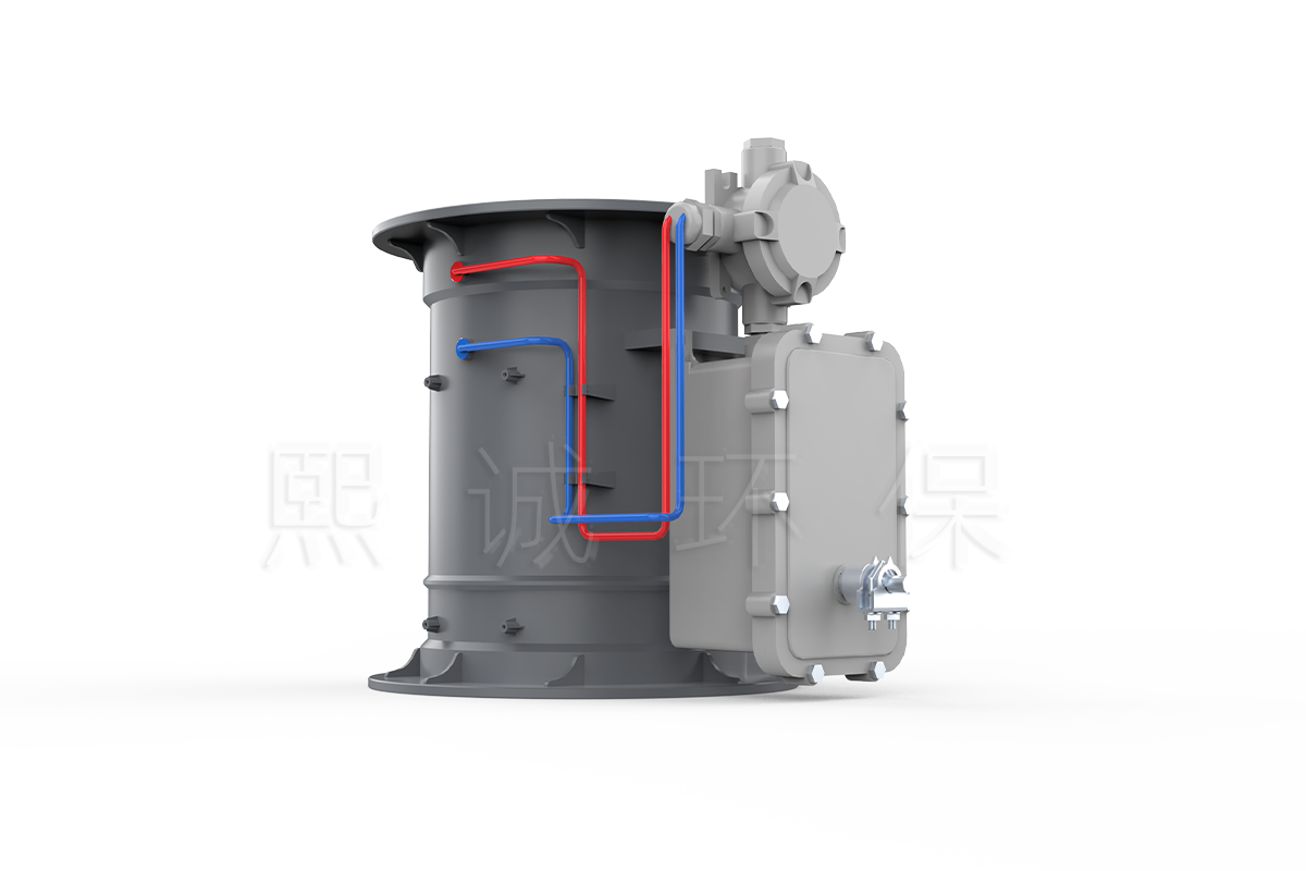
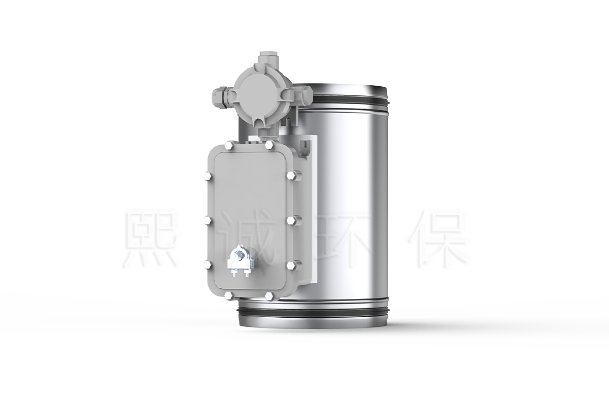
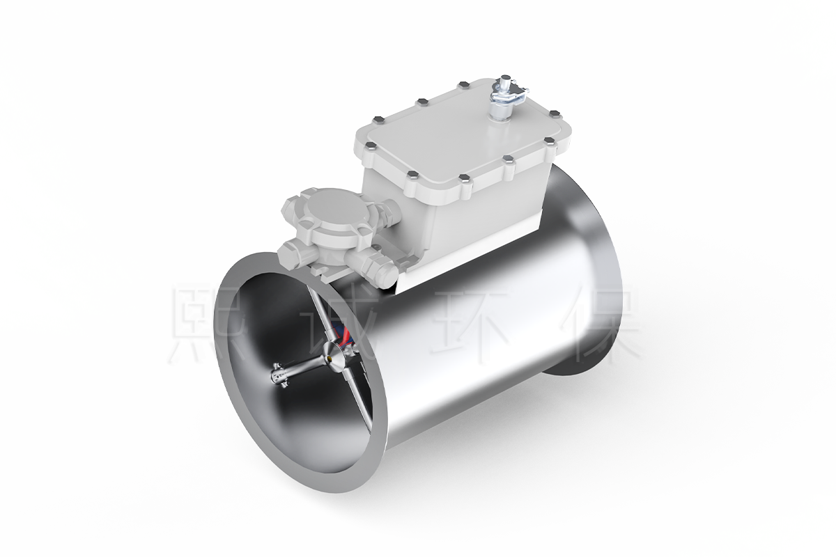
An air damper with explosion-proof actuator regulates ventilation airflow while using electrical actuation selected for the identified hazardous location. This XICHENG family combines a butterfly-damper body, airflow-measurement arrangement and project-specific actuator package for laboratory or industrial supply and exhaust branches. Round PP, custom round and rectangular body configurations are available according to the process, duct and installation requirements.
Selection begins with two separate duties. The mechanical duty defines airflow range, pressure, body material, connection, blade, shaft, measurement method and actuator torque. The hazardous-area duty defines the location classification, gas or dust group, temperature class, ambient conditions, protection concept, electrical accessories and documentation. Both must be satisfied by the exact delivered configuration.
Key Decision Data
- Damper mechanism: a rotating-blade VAV butterfly air damper, not a Venturi valve or life-safety damper.
- Body configurations: molded round PP plus custom PP, galvanized-steel or stainless-steel round and rectangular bodies.
- Round PP sizes: 110, 125, 160, 200, 250 and 315 mm internal diameters with flange and selected socket connections.
- Measured-control references: less than +/-4% error and a 16:1 adjustment ratio for the matching molded-body package; selected custom Pitot arrangements use separate values.
- Working pressure reference: 150-750 Pa for the applicable measured-control package.
- Explosion-protected actuation: actuator model, marking, certificate, zone or division, group, temperature class, ambient limits and cable-entry accessories are selected for the project.
The first five items determine whether the airflow mechanism and body can perform the ventilation duty. The final item determines whether the electrical actuation can be installed at the classified location. Neither approval replaces the other.
What Is Included
The core product is a variable-air-volume butterfly damper with an actuator or actuator enclosure selected for the classified area. A measured-control package may also include differential-pressure pickup, tubing, controller, airflow feedback and a remote setpoint interface. Depending on the electrical design, the controller can be outside the hazardous area while the approved actuator and associated electrical hardware remain at the damper.
The quotation must list the body material and form, nominal size, connection, measurement method, controller, actuator model, torque, travel time, power, command signal, feedback, fail behavior, enclosure, cable glands, junction box and supplied documentation. A generic description such as “explosion-proof actuator” is not sufficient for procurement or installation.
Choose This Product Family When
- The ventilation branch is located in an area that has been formally classified for flammable gas, vapor, mist or combustible dust.
- The branch requires variable or measured airflow rather than a fixed manual damper position.
- A round PP, custom metal or rectangular butterfly body can be matched to the process air stream and duct connection.
- The project team can provide the hazardous-area classification and accept the exact actuator certificate and marking before order.
- Mechanical installation, electrical installation and airflow commissioning will be completed under one approved product schedule.
The product can support laboratory process exhaust, selected chemical or pharmaceutical ventilation, solvent-handling support areas and other classified ventilation branches. Suitability is decided from the actual atmosphere and process, not from the industry name alone. Two facilities performing similar work can have different zone, group and temperature requirements.
What Explosion-Proof Does and Does Not Mean
Explosion-proof describes the protection method and certification of identified electrical equipment. It does not mean the damper is designed to resist a blast wave, isolate an explosion or stop flame propagation through the duct. This product is not a blast damper, fire damper or smoke damper.
The available XICHENG material identifies an explosion-protected actuator and references Chinese implementation-rule requirements for explosion-proof electrical products. It does not establish one universal ATEX, IECEx, zone, gas group, dust group or temperature-class claim for every body shown. The exact supplied actuator and accessories must carry the marking required by the project, and their certificate scope must be reviewed before release.
Where the project only needs standard VAV control outside a classified area, use the Round VAV Butterfly Damper, Rectangular VAV Butterfly Damper or Duct Airflow Control Damper. Where the required mechanism is a Venturi air valve, use the planned Venturi Air Valve with Explosion-Proof Actuator.
Key Specifications, Sizes and Airflow References
The table below separates confirmed product-family information from values that must be returned for the exact project. This distinction is essential because body configuration and hazardous-area electrical scope can vary independently.
Product-Family Specifications
| Selection Item | Available Product Information | Required Confirmation |
|---|---|---|
| Product type | VAV butterfly air damper with a hazardous-location actuator configuration | Do not substitute a Venturi, fire, smoke or blast damper |
| Body forms | Molded round PP; custom round; custom rectangular | Confirm drawing, blade, shaft, seals and leakage requirement |
| Body materials | Molded PP plus custom PP, galvanized-steel or stainless-steel body options | Confirm compatibility and construction for the selected body |
| Round PP size references | 110, 125, 160, 200, 250 and 315 mm internal diameter | Values do not apply to rectangular or custom metal bodies |
| Connection forms | Flange; selected socket sizes; custom connections by drawing | Confirm mating duct and service clearance |
| Published molded-body control error | Less than +/-4% for the corresponding measured package | Confirm body, pickup, controller, actuator and calibration |
| Published molded-body adjustment ratio | 16:1 | Confirm minimum and maximum airflow for the selected size |
| Published custom Pitot option | Less than +/-5% control error and 10:1 adjustment ratio | Applies only to the corresponding custom measured package |
| Published package pressure range | 150-750 Pa | Confirm the actual operating range and available fan pressure |
| Hazardous-area actuator | Explosion-protected actuator configuration identified | Exact model, marking, certificate, zone/group, temperature and ambient limits |
| Electrical accessories | Configuration may require an enclosure, junction box, cable glands, barriers or remote controller | Confirm each component and its installation location |
Round PP Body Size and Airflow Table
These dimensions and velocity-reference flows apply to the matching molded round PP butterfly body. They are useful for preliminary size comparison but do not define the certified electrical scope or the commissioned minimum and maximum airflow.
| Model | Flange OD D1 | Internal D | Body Length L | Socket Depth L1 | At 1 m/s | At 6 m/s | At 10 m/s |
|---|---|---|---|---|---|---|---|
| VAV-R/110 | 185 mm | 110 mm | 240 +/- 3 mm | 25 mm | 34 CMH | 205 CMH | 342 CMH |
| VAV-R/125 | 200 mm | 125 mm | 240 +/- 3 mm | 25 mm | 44 CMH | 265 CMH | 441 CMH |
| VAV-R/160 | 240 mm | 160 mm | 280 +/- 3 mm | 30 mm | 72 CMH | 434 CMH | 723 CMH |
| VAV-R/200 | 280 mm | 200 mm | 300 +/- 3 mm | 30 mm | 113 CMH | 678 CMH | 1,130 CMH |
| VAV-R/250 | 339 mm | 250 mm | 363 +/- 3 mm | 40 mm | 100 CMH | 968 CMH | 1,600 CMH |
| VAV-R/315 | 395 mm | 315 mm | 423 +/- 3 mm | 53 mm | 150 CMH | 1,579 CMH | 2,400 CMH |
The DN250 row retains the published 100 CMH value at 1 m/s even though it is lower than expected from the other entries. Confirm the approved selection data before using that value. Custom round and rectangular bodies require their own size, airflow and pressure-loss schedule.
Flange and Socket Mechanical Envelope
The round-body drawing distinguishes socket and flange connections. D is the internal diameter, D1 is the flange outside diameter, L is the body length and L1 is the socket insertion depth or flange-end reference. The actuator enclosure and linkage add a separate service envelope that must appear on the approved drawing.
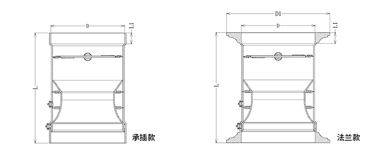
Use the drawing to check connection form and dimensional terminology, not as a universal envelope for every hazardous-area assembly. Reserve access to the enclosure cover, glands, junction box, shaft coupling, pressure tubing and mechanical fasteners. The rectangular configuration needs a separate W x H fabrication drawing.
Butterfly Damper Body and Measurement Options
The hazardous-location actuator does not determine the damper body. Body form, material and measurement method must be selected from the duct, process air stream, airflow range and maintenance requirements. Available configurations include molded PP and custom round or rectangular butterfly-damper arrangements.
| Body Configuration | Confirmed Family Information | Best-Fit Use | Items to Confirm |
|---|---|---|---|
| Molded round PP | 110-315 mm internal-diameter references, flange or selected socket connection, integrated pressure-pickup geometry | Round laboratory or process branches that require a nonmetallic body | Chemical compatibility, exact size, connection, minimum signal and actuator fit |
| Custom round | PP, galvanized steel or stainless steel identified; flange or socket by project drawing | Nonstandard diameter, material, connection or measurement arrangement | Dimensions, wall and blade construction, seals, shaft, pickup, leakage and pressure loss |
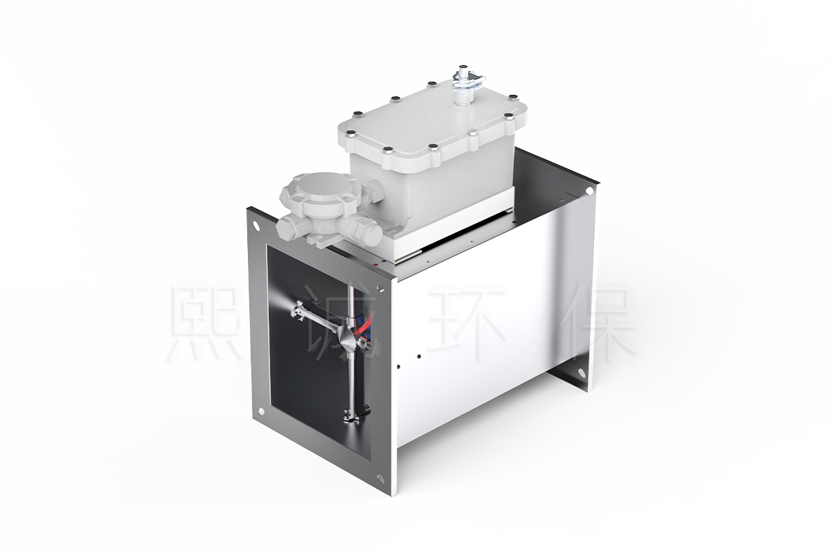
| Custom rectangular | Rectangular butterfly configuration shown with hazardous-location actuator enclosure | Rectangular ductwork or a custom W x H transition constraint | W x H, blade/shaft arrangement, torque, casing strength, leakage and service envelope |
Molded Round PP Configuration
The molded round body uses flame-retardant PP, with V-2 stated as the standard body grade and V-0 available as a custom option. Its construction includes an approximately 5 mm molded wall, reinforced flange features and a PP+GF blade with silicone covering. Pressure pickup connections support measured airflow control.
This configuration offers a repeatable size table and a compact round connection. It remains necessary to review every component exposed to the air stream, including blade covering, shaft parts, fasteners, tubing and pickup fittings. The external actuator enclosure may avoid direct contact with the air stream, but ambient chemicals, washdown, humidity and temperature can still affect it.
The published measured-control values for the matching molded configuration include less than +/-4% airflow-control error and a 16:1 adjustment ratio. These are package values. They require the correct body relationship, clean pressure paths, a matched controller and actuator, sufficient duct pressure and field commissioning.
Custom Round and Rectangular Configurations
Custom bodies allow the air damper to match a nonstandard round diameter, rectangular duct, material requirement or field connection. Available custom options include PP, galvanized steel and stainless steel, together with round or rectangular forms and flange or socket connections. Selected custom arrangements use a Pitot-tube-style measurement section.
Customization changes more than the outside shape. A rectangular blade may require a different shaft and actuator torque from a round body at the same airflow. Metal-body corrosion resistance depends on the selected alloy or coating, while galvanized construction should not be assumed suitable for every chemical exhaust stream. The fabrication drawing must identify body dimensions, blade arrangement, shaft, seals, connection, measurement points and actuator mounting.
Available data for the custom Pitot measurement option lists less than +/-5% airflow-control error and a 10:1 adjustment ratio. Do not apply the molded PP table or 16:1 ratio to a custom body unless the final product schedule explicitly confirms them.
Measurement and Material Boundaries
Airflow measurement and hazardous-area protection solve different problems. The pressure pickup and controller determine how airflow is measured and regulated. The actuator’s protection concept determines whether its electrical construction is suitable for the classified location. A strong airflow signal does not establish explosion protection, and an approved actuator does not establish airflow accuracy.
Provide gas and dust composition separately from the exhaust chemistry. A substance can drive both corrosion and hazardous-area decisions, but the tests and component boundaries are different. The body and seals must tolerate the process stream, while the actuator, enclosure and cable entries must match the formal electrical classification and ambient exposure.
Where deposits or condensate can enter the pickup system, define tubing material, drainage, inspection and cleaning. Measurement maintenance must be possible without compromising the certified enclosure or cable entries. Any field modification to an explosion-protected enclosure, gland or shaft interface requires approval under the applicable documentation.
Explosion-Proof Actuator and Electrical Scope
The actuator cannot be selected until the hazardous location is defined. “Explosion-proof” is not one universal grade. The applicable protection concept, marking and certificate depend on the atmosphere, installation country and equipment location.
Exact Area Classification Comes First
Provide the project classification exactly as issued by the responsible engineer. Depending on the applicable system, this may include zone or division, gas or dust group, temperature class, equipment category or protection level, ambient-temperature range and indoor or outdoor exposure. Also identify whether the actuator, controller, junction box, local isolator, sensor and cable entries are inside or outside the classified boundary.
The chemical name alone is not a classification. Concentration, release grade, ventilation, ignition temperature, dust properties and process conditions can affect the result. XICHENG should not choose a zone or group from a brief description such as “solvent laboratory.” That information must come from the project’s hazardous-area dossier.
Actuator Certificate Versus Complete Assembly
The available product material identifies an explosion-protected actuator and references Chinese implementation-rule requirements for explosion-proof electrical products, including CNCA-C23-01:2019 and CCEC-C23-01:2019. Those references do not by themselves establish the exact certificate, marking or geographic acceptance of every illustrated damper package.
Before order, the submitted actuator data should identify manufacturer, model, certificate number, marking, protection concept, gas/dust group, temperature class, ambient range, enclosure rating and any installation conditions. The same review applies to cable glands, junction boxes, conduit entries, barriers and auxiliary switches. If a component is outside the classified area, the drawing should show that boundary.
An actuator certificate covers the equipment named on that certificate. It does not automatically certify the PP or metal damper body as a complete explosion-proof assembly. A whole-damper claim requires evidence that explicitly covers the complete model and configuration. Without it, the correct description is an air damper configured with a selected explosion-proof actuator.
Torque, Speed, Signal and Fail Behavior
Hazardous-area suitability does not replace normal actuator selection. The actuator must provide enough torque for the blade, shaft, seals and expected pressure load. A rectangular blade or larger custom body can require a different drive from the molded round PP body. Linkage geometry and shaft coupling must fit without reducing the certified enclosure integrity.
Specify travel time from the control sequence rather than choosing the fastest available actuator by default. A two-second fast-actuator option is available for selected butterfly configurations, but the exact explosion-protected actuator data must be confirmed for the chosen model. Controller response, full actuator travel and final airflow stabilization are different events and should have separate acceptance criteria.
State power supply, on/off or modulating command, feedback signal, spring-return or non-spring-return behavior, de-energized position and response after power restoration. The required safe position depends on the process risk assessment. “Fail open” or “fail closed” should never be inferred from the product name.
VAV Control and System Integration
The VAV loop measures airflow, compares it with the active setpoint and moves the butterfly blade to correct the difference. Hazardous-area protection changes how the electrical components are selected and installed; it does not change the basic control relationship.
Airflow Measurement and Control Loop
The molded round PP configuration uses body pressure pickups, while selected custom arrangements use a Pitot-tube-style measurement section. The controller converts differential pressure into airflow using the relationship for the selected body. When measured flow differs from the setpoint, the actuator changes blade position until the loop settles within its commissioned range.
The branch fan must provide sufficient pressure at maximum demand. At minimum flow, the measurement signal must remain usable and the blade must retain control authority. If the actuator reaches its travel limit, further controller output cannot correct a fan-pressure or sizing problem. Airflow feedback should be verified against the accepted field measurement method.
Controller Location and Interfaces
The controller can be integrated with the actuator only when the exact controller/actuator package is approved for the installed location. Another common arrangement places the airflow controller in a nonclassified area and commands an approved actuator at the damper. The electrical design determines whether barriers, isolators, protected wiring or specific glands are required.
Define analog setpoint and feedback ranges, digital interlocks, local override and BMS communication. If a network interface is used, state where the communication device is installed and how it is protected. The controller should retain the approved local fallback during communication loss rather than relying on a continuous remote command with no safe-state definition.
System Boundaries
The product does not classify the room, detect a gas release, provide process shutdown logic or replace the building’s hazardous-area electrical design. It also does not replace the fan, variable-frequency drive, ductwork, gas detection, emergency ventilation sequence, airflow balancing or room-pressure verification.
Do not use this product as a fire or smoke damper unless a separate certified life-safety device is specified. Do not describe it as a blast damper. If an explosion-isolation or pressure-relief function is required, select equipment specifically tested for that duty and coordinate it with the ventilation system.
Applications, Selection and RFQ Information
A hazardous-area air damper should be selected from the classified-location dossier and the airflow schedule together. The process name can indicate where to investigate, but it does not replace either document.
Good-Fit Applications
Potential applications include laboratory process exhaust, pharmaceutical or chemical production support, solvent-handling ventilation, paint or coating areas, battery or gas-service rooms and other supply or exhaust branches with a formally identified hazardous atmosphere. The product can regulate variable airflow, maintain a scheduled air volume or participate in room-pressure and emergency-ventilation sequences when the required sensors and controller are included.
A molded PP body is useful where a round nonmetallic damper is appropriate for the process air stream. Custom stainless-steel, galvanized-steel, PP round or rectangular configurations can address other duct and fabrication requirements. Material selection still requires the actual chemical, temperature, condensate and cleaning conditions.
Conditions Requiring Another Product
Use the standard Round VAV Butterfly Damper or Rectangular VAV Butterfly Damper when the actuator and controls are outside the classified area or no hazardous-location protection is required. Use the Duct Airflow Control Damper when measured airflow and room-pressure control are the primary requirements without a classified actuator.
Evaluate the planned Venturi Air Valve with Explosion-Proof Actuator when the airflow-control mechanism must be Venturi rather than butterfly. Use a certified fire, smoke, blast-isolation or explosion-relief product when any of those life-safety functions are required. The product on this page is not a substitute for them.
Selection Sequence
- Obtain the formal hazardous-area classification and identify every component located within its boundary.
- Define the application, normal control mode, emergency mode and required de-energized position.
- List minimum, normal, maximum and emergency airflow together with available pressure.
- Select molded round PP, custom round or rectangular body from the duct and process conditions.
- Confirm connection, body dimensions, blade, shaft, seals, measurement method and service access.
- Select actuator torque, travel time, power, command, feedback and fail mechanism from the mechanical duty.
- Match the exact actuator and electrical accessories to the required marking and certificate scope.
- Define controller location, barriers or isolators, cable entries, junction boxes and wiring method.
- Complete the I/O list, fan interlocks, gas-detection interface, BMS points and communication-loss behavior.
- Issue airflow and hazardous-area inspection requirements for installation and handover.
Do not allow the certification label to drive the mechanical selection backward. An approved actuator with insufficient torque or an unsuitable shaft connection is not a valid configuration. Likewise, a mechanically correct damper cannot be installed in the classified area until its actuator and electrical accessories match the project requirements.
Required Project and Certification Data
For the airflow and mechanical schedule, provide the damper tag, service, body material, round diameter or rectangular W x H, connection, minimum/normal/maximum/emergency airflow, available pressure, installation orientation and service clearance. Include the process gases, vapors, dust, temperature, humidity, condensate and cleaning conditions.
For the hazardous-area schedule, provide the governing standard, zone or division, gas and dust group, temperature class, equipment category or protection level, ambient range, indoor/outdoor exposure and any special installation conditions. Identify which parts are inside the classified area and which are remote.
For the actuator and controls, state torque or force, rotary or linear motion, travel time, power, control signal, feedback, fail position, auxiliary switches, enclosure requirement, glands, junction box, barriers, controller location and BMS interface. Attach the area-classification drawing, duct layout, controls schematic and electrical single-line diagram when available.
The returned submittal should identify the exact actuator model, applicable certificate and marking, body configuration, drawing, airflow data, supplied electrical accessories and excluded field components. Procurement should compare those documents with the valve schedule before release.
Installation, Commissioning and Documentation
Installation must preserve both mechanical performance and the protection features of the selected electrical equipment. Work should follow the approved damper drawing, actuator instructions, certificate conditions, hazardous-area wiring design and site permit procedure.
Mechanical Installation
Confirm airflow direction, body orientation, connection and service envelope before lifting the assembly into place. Support the adjoining duct independently and align flange or socket connections without pulling the damper body out of shape. Protect the actuator enclosure, glands, pressure pickups and tubing during handling.
Check shaft alignment and linkage movement before applying power. The blade should complete its permitted travel without binding or striking a stop. Leave access to the enclosure cover, manual controls if provided, terminal compartment, junction box, fasteners and pressure tubing. A rectangular custom body also requires verification of blade/shaft support and actuator mounting under the installed orientation.
Connect pressure tubing to the correct high and low ports. Keep it supported, dry and free from leaks, sharp bends or trapped liquid. Where the air stream can deposit solids or condensate, include an inspection and cleaning arrangement that does not require unauthorized modification of the certified electrical enclosure.
Electrical Installation in the Classified Area
Verify the actuator nameplate and certificate against the project area classification before wiring. Confirm voltage, frequency, control signal, feedback, auxiliary contacts, protective earth and maximum ambient temperature. Use only cable glands, conduit entries, blanking elements, junction boxes and barriers approved for the applicable protection method and cable type.
Do not drill, machine or substitute enclosure entries in the field unless the manufacturer and governing procedure permit it. Maintain required thread engagement, seals, clearances and cable support. Where the controller is outside the classified area, verify the interface wiring and any required isolator or barrier. Mark the boundary clearly on the wiring drawing.
Test de-energized position, emergency command, local isolation and restart behavior before normal operation. The fan interlock and process shutdown sequence should prevent the damper from being treated as the only safety action during a gas release or electrical fault.
Airflow Commissioning
- Inspect the body, blade, shaft, actuator, enclosure, glands, tubing and wiring against the approved submittal.
- Verify rotation direction and mechanical travel without exceeding the actuator or linkage limits.
- Confirm the controller uses the correct body size and measurement relationship.
- Zero the pressure sensor under the specified no-flow or equal-pressure condition.
- Enter minimum, normal, maximum and emergency airflow values from the valve schedule.
- Apply each setpoint and compare controller airflow with the accepted field measurement.
- Verify command, feedback, fail position, interlocks and recovery after power or communication loss.
- Record airflow, blade position and available pressure at each accepted operating point.
If maximum flow cannot be reached with the blade fully open, check fan pressure and duct resistance. If low flow is unstable, check body sizing, pressure signal, tubing and controller range. Do not compensate for a mechanical or measurement problem by entering an unsupported calibration value.
Handover and Maintenance
The handover file should include the approved damper drawing, actuator data sheet, applicable certificate and marking, certificate conditions, electrical accessory list, wiring diagram, controller settings, airflow test record and hazardous-area inspection record. Keep the exact actuator and enclosure model visible in the maintenance register.
Inspect the blade, shaft, pressure pickups, tubing, actuator, enclosure, glands, cable and grounding at the required interval. Open an explosion-protected enclosure only under the applicable isolation and permit procedure. Replacement components must preserve the approved marking, interface and installation conditions; a physically similar actuator is not automatically an acceptable substitute.
Recommission airflow after changes to the body, actuator, controller, sensor, tubing, fan or duct system. Repeat the hazardous-area review after any change to the process atmosphere, classification, ambient condition, cable entry or enclosure.
Related Laboratory Air Damper Products
For a nonclassified circular branch, use the Round VAV Butterfly Damper. For a nonclassified rectangular branch, use the Rectangular VAV Butterfly Damper. Where measured duct airflow or room pressure is required without hazardous-location actuation, use the Duct Airflow Control Damper.
If the required airflow mechanism is Venturi rather than a butterfly blade, review the planned Venturi Air Valve with Explosion-Proof Actuator. The two pages keep body mechanism, size tables and control behavior separate while applying the same rule that certification claims must match the exact supplied component.
Frequently Asked Questions
Is the Complete Damper ATEX or IECEx Certified?
Not as a universal claim. The available XICHENG material identifies an explosion-protected actuator configuration but does not provide one complete-assembly ATEX or IECEx certificate covering every illustrated damper. The exact actuator model, marking and certificate must be returned for the selected project. A whole-damper claim requires separate evidence that explicitly covers that assembly.
Is an Explosion-Proof Air Damper a Blast Damper?
No. Explosion-proof describes the protection of identified electrical equipment against becoming an ignition source under its certified conditions. A blast damper is designed for pressure-wave or blast-loading duty and requires different testing and construction. This product is also not a fire or smoke damper.
Which Body Materials Are Available?
Available butterfly-body configurations include molded PP, custom PP, galvanized steel and stainless steel in round or rectangular forms. Availability and construction vary by configuration. Confirm body, blade, shaft, seals, pressure pickup and connection for the actual process stream and drawing.
What Actuator Data Must Be Confirmed?
Confirm manufacturer, model, certificate, marking, zone or division suitability, gas/dust group, temperature class, ambient range, enclosure rating, torque, travel time, power, command, feedback, fail behavior, shaft interface, glands and junction box. Do not release the order from a generic “explosion-proof” description.
Can the Product Control Room Pressure?
It can participate in room-pressure control when the selected controller, room differential-pressure sensor, supply/exhaust relationship and control sequence are included. The damper’s airflow pickup does not replace the room sensor, and the actuator’s explosion protection does not define the pressure-control performance.
What Documents Are Needed Before Order?
Provide the hazardous-area classification, airflow schedule, available pressure, duct/body requirements, process conditions, actuator and control specification, electrical single-line diagram, I/O list and installation boundary. The returned submittal should identify the exact actuator certificate and marking, supplied accessories, damper drawing and applicable airflow data.
Contact the Xicheng Engineering Team Today
Send the hazardous-area classification, damper schedule, airflow calculations, duct drawing and electrical/control requirements. Include the required body material and form, actuator duty, fail position, controller location and documentation standard. XICHENG will use these inputs to prepare the configured product schedule, drawing, applicable actuator documentation and quotation.
Shenzhen Office: No. 34 Zhenxing Road (Shengtaian Heavy Industrial Park B), Loucun, Guangming New Dist, Shenzhen, Guangdong, China
WhatsApp: +86 181 2647 8161
Engineering Mailbox: fanalax34@gmail.com