


Description
Radioisotope Fume Hood for Radiochemical and Radiopharmacy Work
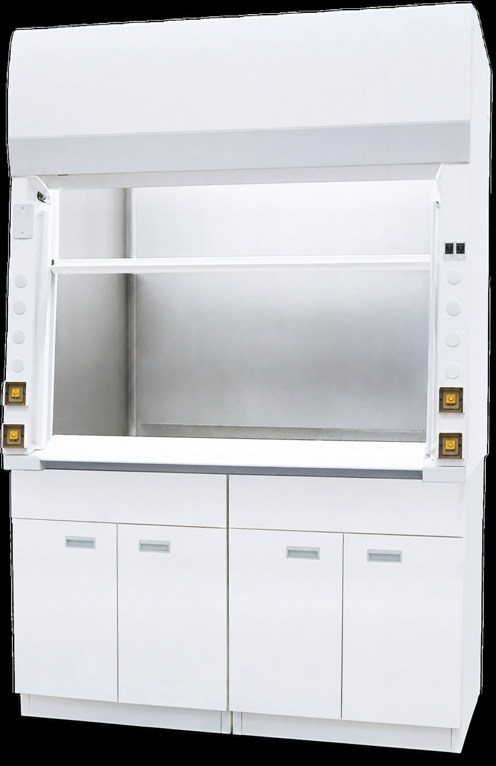
A radioisotope fume hood is a ducted specialty enclosure for radiochemical and radiopharmacy procedures involving beta- and gamma-emitting materials. It draws room air through a controlled sash opening and into an external exhaust path while providing a work zone designed around cleaning, decontamination and the physical loads created by shielding and radiochemical equipment. The defining construction is a coved, continuously welded stainless-steel interior joined to a spill-retaining, reinforced work surface rather than an ordinary liner installed inside a general-purpose hood.
XICHENG configures the hood around the actual source material, process, equipment and facility conditions. The project can define the chamber material and finish, vertical sash opening, worktop reinforcement, shielding interfaces, equipment clearances, service fixtures, exhaust connection, airflow monitor, drain or waste route and control signals. The approved quotation, drawings and component schedule identify what the hood includes and which items remain part of the building exhaust, radiation-protection or facility package.
What Is
The enclosure is intended for procedures that may release airborne radiochemical contamination and that also require surfaces capable of repeated cleaning. Type 304 stainless steel is the reference material for the interior lining and work surface. Coved transitions reduce sharp internal corners, continuous welds reduce joints where residues can collect, and a smooth accessible work zone makes visual inspection and cleaning more practical. A dished or otherwise spill-retaining work surface helps keep small liquid releases within a defined area while the response and waste route are managed under the laboratory procedure.
The work surface and supporting structure are also reviewed for lead bricks, an L-block, a chest shield, shielded containers and radiopharmacy instruments. These items create different load patterns. A uniform layer of shielding may act as a distributed load, while equipment feet, stacked bricks and a shielded waste vessel can apply concentrated loads at specific positions. The hood can be reinforced and laid out for these conditions, but the load, footprint, support points and location must be supplied before the structure is approved.
A vertical-rising sash provides access for setup and operation while retaining a physical plane between the operator and the work zone. Horizontal sash panels are not the reference arrangement for the radioisotope fume hood type. The selected opening height, viewing area, equipment envelope and operator reach must be coordinated together so that a shield or instrument does not obstruct sash travel, block the intended airflow path or force work too close to the opening.
Common commercial width directions of 4, 5, 6 and 8 ft provide a starting point for room planning. Nominal width does not establish the clear internal width, working depth, sash opening, exhaust collar or available space around shields and instruments. The final layout therefore begins with the equipment and shielding plan, then sets the chamber, opening, service and exhaust geometry on the approved drawing.
Why the Work Zone Is Different
An ordinary stainless-steel fume hood may have a metal liner, but material appearance alone does not establish a radioisotope configuration. Gaps between panels, exposed joints, sharp corners, recessed penetrations and inaccessible baffle areas can complicate cleaning and inspection. A standard worktop may also lack the spill-retaining geometry or structural support needed for shielding blocks and heavy radiopharmacy equipment. The radioisotope design addresses these issues as one work-zone system rather than treating the liner, worktop and base as unrelated components.
Cleanability depends on fabrication details as much as alloy grade. Weld continuity, corner radii, surface finish, baffle access, service-penetration locations and the junction between liner and work surface all influence where residue can remain. The cleaning or decontamination chemicals must also be disclosed because they may affect the preferred stainless grade, finish, seals and fixtures. Type 316 can be evaluated where process chemistry or cleaning conditions justify it, but it is not automatically the better or necessary choice for every isotope application.
The work zone must also accommodate the actual operating sequence. A radionuclide generator, dose calibrator, L-block, shielded syringe holder or waste container can occupy substantial space and alter operator reach. Tubing, electrical leads, sample transfers and cleaning access add further constraints. Placing equipment only from an external cabinet width can produce a hood that looks large enough but leaves inadequate working clearance or blocks the rear extraction path. The radioisotope fume hood layout therefore follows the process sequence and equipment envelope rather than a generic furniture module.
Product Selection Summary
A radioisotope hood is appropriate when a documented radiochemical process needs both inward exhaust containment and a work zone designed for repeated cleaning, spill control and the physical loads created by shielding and equipment. The first decision is not cabinet width or stainless-steel grade. It is whether the project can define the source material, process sequence, shielding responsibility, equipment layout, cleaning method, exhaust path and waste route well enough to configure the complete installation.
When to Choose a Radioisotope Fume Hood
- The process handles beta- or gamma-emitting materials in a form that can create airborne contamination, vapor, aerosol or surface residue during normal work or cleaning.
- A continuously welded, coved stainless-steel work zone and spill-retaining work surface are required for cleaning and decontamination procedures.
- Lead bricks, an L-block, a chest shield, a dose calibrator, a radionuclide generator, shielded containers or other equipment can be identified with their weights and locations.
- The radiation-protection team can define shielding responsibility, required lead equivalence, coverage, monitoring and source-handling controls separately from the hood cabinet.
- The laboratory can provide an external duct, fan, room-air and discharge arrangement sized for the selected sash position and project airflow criterion.
- Filtration, service fixtures, liquid collection, controls and alarms can be specified as defined interfaces rather than assumed from the radioisotope fume hood name.
Do Not Select a Radioisotope Fume Hood by Name or Stainless-Steel Liner Alone
The word radioisotope does not establish suitability for every radionuclide, activity or physical form. A sealed source, an open volatile compound, a heated solution and a particulate-generating procedure create different airborne, surface, shielding and waste concerns. Selection starts with the actual source term and process, then determines whether a ducted hood is the appropriate engineering control and what additional radiation-protection measures are required.
A stainless-steel liner is also not enough. The buyer must review seam continuity, corner geometry, worktop junctions, penetrations, baffle access, spill retention, finish and structural support. An ordinary stainless hood may still contain joints or load assumptions that do not fit radiochemical cleaning and shielding. Conversely, choosing Type 316 instead of Type 304 does not automatically improve the hood if fabrication, cleaning access, shielding support and exhaust integration remain unresolved.
Do not treat the hood as built-in radiation shielding. Lead lining, lead bricks, an L-block and a chest shield perform different functions and may be supplied by different parties. Their attenuation requirement comes from the radiation-protection assessment, while the hood structure must accommodate their mass, geometry, support and access. If shielding is included in the order, its material, thickness, coverage and interface must be explicitly listed.
Likewise, do not assume that a HEPA filter, carbon filter, bag-in/bag-out housing, airflow alarm, contamination monitor, sink, drain or remote blower is standard. Each item changes the supplied scope, pressure loss, maintenance method, utility requirement or waste route. The quotation must show whether it is hood-mounted, duct-mounted, site-provided or outside the radioisotope fume hood package.
Key Specifications and Reference Configurations
The specification schedule for a radioisotope hood must make reference fields, selectable options and final project values visibly different. The tables below provide a common basis for comparing product configurations without converting a planning width, industry design check or available interface into a universal manufactured value. The quotation and approved drawing govern the dimensions, materials, loads, components and system duties for the selected order.
Product-Family Reference Fields
These fields describe the radioisotope fume hood family’s defining direction. They are suitable for early comparison and design coordination, but they do not replace the final component schedule.
| Specification Field | Reference Product Direction | Final-Configuration Rule |
|---|---|---|
| Product form | Ducted, bench-height specialty laboratory fume hood | Confirm room location, base support, access route, service zone and external exhaust responsibility |
| Primary work | Radiochemical and radiopharmacy procedures involving beta- and gamma-emitting materials | Approve the actual radionuclide, activity, physical form, process and operating procedure |
| Reference interior | Type 304 stainless-steel work zone | Confirm grade, sheet thickness, surface finish, weld finish, exposed components and cleaning chemistry |
| Interior geometry | Coved transitions with continuously welded, low-crevice construction | Confirm corner geometry, penetrations, baffle access, fixtures and liner/worktop junctions on the drawing |
| Work surface | Spill-retaining stainless-steel surface with structural reinforcement | Approve spill geometry, distributed load, concentrated loads, support points and shield/equipment layout |
| Sash | Vertical-rising reference arrangement | Confirm clear opening, travel, stop position, glazing, viewing area, shield clearance and operating height |
| Reference widths | Common 4, 5, 6 and 8 ft planning directions | Final external width and clear chamber dimensions follow equipment, shielding, services and installation constraints |
| Exhaust | Connection to an external ducted exhaust system | Calculate airflow, static pressure, duct, fan, room air, monitoring, filtration and discharge for the approved configuration |
| Configurable interfaces | Shield support, equipment, services, sink/drain, controls and monitoring can be coordinated | Only items listed in the quotation and component schedule are included |
Reference Widths and Working Envelope
The common width series is useful for reserving a laboratory bay and comparing general equipment capacity. The metric directions below are planning equivalents rather than exact external dimensions. A final hood may require a different overall width, depth or height to maintain working clearance, structural support, sash movement, service access and exhaust geometry.
| Common Width | Metric Planning Direction | What the Width Does Not Establish |
|---|---|---|
| 4 ft | Approximately 1200 mm | Clear chamber width, working depth, sash opening, collar, equipment fit, shielding clearance or services |
| 5 ft | Approximately 1500 mm | Clear chamber width, working depth, sash opening, collar, equipment fit, shielding clearance or services |
| 6 ft | Approximately 1800 mm | Clear chamber width, working depth, sash opening, collar, equipment fit, shielding clearance or services |
| 8 ft | Approximately 2400 mm | Clear chamber width, working depth, sash opening, collar, equipment fit, shielding clearance or services |
Prepare the working envelope from the largest operating arrangement, not only from equipment shipping dimensions. Include open doors or drawers, shield movement, sample-transfer space, tubing and cable bends, cleaning reach, baffle removal and the path used to install or remove heavy components. The clear opening must also accommodate setup without making the fully open sash the routine operating position.
Stainless-Steel Work Zone and Decontamination Design
A cleanable radioisotope work zone is defined by the complete exposed surface, not by the alloy name on one liner panel. Material grade, weld continuity, corner geometry, penetrations, surface finish, removable components, spill retention and cleaning access must work together. The selected arrangement should let the laboratory reach and inspect the surfaces included in its operating and decontamination procedures without creating unnecessary joints or inaccessible pockets.
Type 304 as the Reference Interior Material
Type 304 stainless steel is the reference material identified for the work surface and interior lining of a radioisotope fume hood. It provides a durable, smooth and cleanable surface when fabricated with continuous welds and coved transitions. The material should extend across the intended primary work zone, including the rear and side surfaces, work surface and the transitions that would otherwise create residue traps.
The grade designation does not define sheet thickness, fabrication quality or surface condition. Those fields should appear separately on the component schedule. A thin panel with poorly finished joints is not equivalent to a continuously welded chamber, and an attractive exterior finish does not prove that concealed seams, penetrations or the liner/worktop junction meet the cleaning requirement. Review the complete chamber drawing and fabrication notes rather than relying on a general `stainless steel interior` description.
The baffle and other interior components also require attention. A removable or accessible baffle can support inspection and cleaning, but its removal method, fasteners, edges and clearances must not introduce uncontrolled gaps or difficult-to-clean pockets. The exhaust collar and transition should be coordinated with the duct material and maintenance plan because contamination may extend beyond the visible work surface.
Welds, Corners, Penetrations and Baffle Access
Continuous welds reduce open seams between chamber panels and help create a continuous cleaning surface. Coved or radiused corners replace sharp internal junctions with transitions that are easier to wipe and inspect. Welds should be ground or finished to the specified condition without leaving undercuts, pinholes, rough ridges or unsealed overlaps in the primary work zone. The required finish should be defined before manufacture rather than judged only from a distant product photograph.
Service penetrations should be kept out of the primary contamination area where practical. When a fixture, sensor, cable, pipe or drain must pass through the chamber, its sleeve, seal, exposed fastener and rear access should be shown on the drawing. Exterior access panels can allow maintenance without opening additional joints inside the work zone. The service layout should also preserve a clear cleaning path around fixtures and equipment.
Baffle access should be reviewed against the laboratory’s inspection method. If the baffle is removable, the team needs a controlled way to release, support, clean and reinstall it without damaging seals or spreading contamination. If it remains fixed, the cleaning procedure must address the accessible surfaces and any spaces behind it. A general statement that the hood is cleanable is incomplete until the surfaces, access method and acceptance condition are identified.
| Cleanability Field | Preferred Design Direction | Project Detail to Specify |
|---|---|---|
| Interior panels | Continuous stainless-steel work-zone surfaces | Grade, thickness, finish, panel boundaries and exposed area |
| Seams and joints | Continuous welded construction in the primary work zone | Weld type, finish, inspection condition and acceptable discontinuities |
| Corners | Coved or radiused transitions | Corner radius, worktop junction and treatment around penetrations |
| Baffle | Accessible or removable arrangement | Removal method, fasteners, handling, rear access, cleaning and reinstallation |
| Fixtures and penetrations | Minimized and positioned outside the main contamination area where practical | Location, sleeve/seal, exposed hardware, rear access and cleaning clearance |
| Surface finish | Smooth, inspectable contamination-facing finish | Finish designation, weld treatment, cleaning agents and acceptance method |
| Spill retention | Dished or otherwise retaining work surface | Retaining geometry, capacity basis, edge details, response method and waste route |
Spill Retention, Sink and Liquid-Waste Route
A dished or spill-retaining work surface helps confine small liquid releases and cleaning liquids long enough for the approved response. It is not a substitute for secondary containment, an operating procedure or a waste plan. The retaining geometry must remain usable after equipment and shielding are placed; a shield that bridges the dished area or blocks access can change how liquid moves and how the surface is cleaned.
A sink or cup sink can be added when the process and cleaning procedure require it, but the drain route must be defined as part of the radiological and facility design. The project should state whether liquid is collected, monitored, held for decay, transferred to a controlled waste system or handled by another approved method. A visible drain fitting does not establish that direct discharge to a building sewer is acceptable.
Where no permanent drain is provided, the cleaning procedure should define how liquids are applied, recovered and transferred. Removable collection trays, absorbent materials or dedicated containers may be part of the laboratory method, but their use and compatibility are set by the facility. The hood design should preserve access for that method and avoid placing sensitive electrical components or unsealed joints in likely spill paths.
Define the Decontamination Method Before Manufacture
Provide the expected routine cleaning agents, stronger decontamination agents, contact times, temperatures, application method and rinse requirements. Identify which surfaces are cleaned after each operation, which are inspected periodically and which require access only during maintenance. The material and component review should include normal operation, spill response and decommissioning rather than only the least demanding routine wipe-down.
Also define the acceptance method. Visual cleanliness, removable contamination limits, wipe-test criteria, surface-condition inspection and recordkeeping may be governed by the facility’s radiation-safety program. XICHENG can configure the work zone and access around those requirements, but the hood does not create or validate the site’s decontamination procedure. The buyer’s procedure and acceptance criteria remain the basis for determining whether the cleaned installation can return to service.
Once the interior construction and cleaning method are established, the next design task is to place shields and equipment without exceeding structural capacity or compromising sash travel, airflow and access. That coordination is addressed separately because a cleanable surface does not, by itself, approve a heavy radiopharmacy layout.
Shielding Loads and Radiopharmacy Equipment Integration
The radioisotope-hood structure must support the approved operating layout without turning a shielding or equipment decision into an assumption. Lead bricks, an L-block, a chest shield, a dose calibrator, a radionuclide generator and a shielded waste container affect the worktop in different ways. Their mass, footprint, position, movement and required access should be established before the work surface, base support, sash and services are finalized.
Stainless Steel Is Not Radiation Shielding
Stainless steel creates a durable and cleanable contamination-facing surface; it does not provide a complete radiation-shielding solution. The required attenuation depends on the radionuclide, activity, emission energy, source geometry, distance, handling time and operator position. Those inputs belong to the radiation-protection assessment, which determines whether lead, another shielding material, distance, time controls, remote tools or a more enclosed system are required.
A radioisotope fume hood can be configured to carry or interface with shielding, but the shielding scope must be explicit. Lead bricks placed by the user, a removable L-block, a sliding chest shield and lead-lined hood panels are not interchangeable. They cover different directions, occupy different space and apply different loads. The approved drawing should show which items are supplied with the hood, which are supplied by the customer or radiation-protection contractor and where each interface begins.
If lead lining is included, specify its material, thickness or lead equivalence, coverage, joints, support, encapsulation, access and replacement method. A statement such as `lead-lined option available` is not enough to establish protection for the selected source. The project radiation-safety team remains responsible for confirming that the completed shield arrangement addresses the intended operation.
Approve Distributed and Concentrated Loads Separately
Distributed load describes mass spread over a stated area. Concentrated load describes mass applied through smaller contact points or in a localized region. A worktop can satisfy a distributed-load check while still requiring additional reinforcement under a heavy instrument foot, an L-block base or a stack of lead bricks. The structural review therefore needs both the total mass and the way that mass enters the work surface and support frame.
Provide a plan view with each item identified. For movable shields or containers, show all normal positions and the path between them. Include the center of gravity and any overturning or rolling condition for tall or mobile components. If equipment is supported through the worktop, identify the cutout, flange, fasteners and below-worktop clearance. If it is supported independently, show how that structure passes through or around the hood without creating cleaning or airflow conflicts.
Temporary conditions can govern the design. Setup may place equipment near the front edge before it is moved into its operating position, and maintenance may transfer a shield to one side of the worktop. A waste container becomes heavier as it fills. The load schedule should include these foreseeable states rather than only the final neat arrangement shown in a product photograph.
Equipment and Shielding Layout
Radiopharmacy equipment changes more than the required width. A radionuclide generator needs loading and removal clearance, a dose calibrator may require a worktop opening or below-bench space, and an L-block occupies both worktop area and the operator’s line of sight. A chest shield can reduce the usable sash opening, while shielded waste may need frequent access without crossing the clean operating path. The layout should follow the real sequence of receipt, preparation, measurement, transfer and waste handling.
Service positions should be coordinated after the equipment arrangement is stable. Electrical receptacles, data connections, gas, vacuum, water and drain points should remain accessible without routing hoses or cables across spill paths or through the sash plane. Controls and displays should be visible from the normal working position but outside likely contamination zones. Maintenance access must allow equipment removal without dismantling fixed shielding or cutting permanent service lines.
The airflow path also needs clearance. Large shields and instruments can interrupt the sweep from the sash opening toward the baffle. Keep the rear extraction openings clear and preserve space between apparatus and the side/rear surfaces. The final layout should be evaluated at the intended sash position and with the equipment installed, because an empty hood airflow check cannot represent a heavily occupied work zone.
Exhaust, Monitoring, Filtration and Utility Interfaces
The hood cabinet and the building exhaust system form one operating airflow path. The selected sash condition sets the open area, the containment criterion determines the required inward-air condition, and the duct, fittings, filter or treatment equipment and discharge stack create the system pressure loss. A fan must provide the required flow at that total duty while the room supplies enough make-up air to prevent pressure and cross-draft conditions from disrupting the hood face.
Size the Hood and Building Exhaust Together
Start with the intended operating sash position and the acceptance criterion required by the project. The airflow quantity cannot be selected from nominal hood width alone because clear opening dimensions, baffle arrangement, equipment blockage, duct connection and room conditions change the installed requirement. The calculation should identify the hood resistance and every downstream pressure loss at the design flow.
Room-air coordination is part of this calculation. Supply diffusers, doors, traffic and adjacent exhaust devices can create cross drafts at the sash. Inadequate make-up air can make the room excessively negative and reduce available airflow, while a poorly located supply diffuser can disturb containment even when the fan is moving the expected volume. Review the installed location and room ventilation layout before fixing the fan duty.
The occupied work zone should be considered during the final assessment. Shields and instruments can change internal airflow distribution and may block baffle openings. The approved operating layout, normal sash position and representative equipment should therefore be present or simulated during site verification. Fan status or a nominal controller command is not proof that the intended inward airflow and containment condition have been achieved.
Airflow Monitoring and Alarm
An airflow monitor or alarm provides information about the hood’s ventilation condition. Depending on the selected package, it may use face velocity, pressure or another airflow-related input and may provide local indication, audible/visual alarm, relay output or BMS communication. Its range, setpoint, delay, alarm behavior, power and signal interfaces should be defined with the airflow-control strategy.
An airflow monitor is not a radiation monitor. It does not identify radionuclide, activity, surface contamination, airborne radioactivity or operator dose. If the facility requires radiation or contamination monitoring, that equipment and its sampling point, range, alarm, data recording and calibration must be specified separately. The two systems may exchange status signals, but they answer different safety questions.
Commissioning should verify the airflow monitor against the accepted installed condition rather than only checking that its display turns on. Confirm the normal and alarm states at the approved sash position, verify signal outputs and document the response to loss or reduction of exhaust. Any interlock with sash, fan, room controls or process equipment must follow the approved sequence of operation.
Filtration and Discharge Are Process Decisions
Filtration should be selected from the contaminant form and the facility’s discharge strategy, not from the radioisotope fume hood name. A particulate filter does not remove every gas or vapor, and an adsorbent selected for one compound may not address another. The project must identify the expected aerosol, particulate, vapor or gas, loading, chemical conditions, required removal or monitoring objective and final disposal method.
Where a filter is required, define the filter type, efficiency or performance basis, housing, prefilter, pressure-drop allowance, change method, isolation, leak-test or monitoring requirements and waste classification. A bag-in/bag-out housing may reduce exposure during filter change for an applicable design, but it is not automatically included. Its space, access and pressure loss must be included in the duct and fan calculation.
Some facilities may require sampling or monitoring of the exhaust stream rather than, or in addition to, filtration. Others may control releases through process restrictions, source capture and an approved discharge point. The final arrangement depends on the radionuclide, physical form, activity, operating frequency and local program. The hood can provide the required connection and control interfaces, but it cannot establish discharge compliance without the complete system and project criteria.
Applications, Product Selection and Project Delivery
A radiochemical fume hood is selected from the complete work process, not from the department name or a generic statement that radioactive material is present. The buyer should identify how the source is received, opened, transferred, heated, mixed, dispensed, measured, cleaned and discarded. That sequence reveals where airborne contaminants may be generated, where surfaces require cleaning, where shielding is needed and which equipment, services and exhaust functions must be integrated.
Good-Fit Radiochemical and Radiopharmacy Work
The radioisotope fume hood family can be evaluated for radiochemical preparation, radiopharmaceutical dispensing, tracer-solution handling, open-source sampling and related laboratory procedures where inward airflow and a cleanable work zone are appropriate controls. It is particularly relevant when the work surface must support shields or instruments and when residues, small spills or cleaning liquids require a coved, welded and spill-retaining interior.
The radioisotope fume hood may also support integration of a radionuclide generator, dose calibrator, L-block, chest shield or shielded waste container. Suitability is not established by the equipment name alone. The process must fit within the clear work zone, the load must be approved, services must remain accessible, and shielding must not obstruct sash operation, cleaning or the intended airflow path.
For each application, the radiation-protection team should determine whether the hood addresses the airborne-contamination part of the control strategy and what additional source shielding, distance, time, monitoring and operating procedures are required. A low-activity procedure may still need careful contamination control, while a higher-shielding application may require a glovebox, hot cell or remote-handling system even if local exhaust is also present.
When a Radioisotope Fume Hood Is Not a Good Fit
Do not use the radioisotope fume hood as a substitute for biological containment. A biological safety cabinet has a different airflow, filtration, work-practice and certification framework. If biological and radiological hazards occur together, the responsible safety teams must define a device and procedure that addresses both; a radioisotope hood should not be relabeled as a biosafety solution.
Do not select it when the required shielding and remote manipulation call for a fully enclosed glovebox or hot cell. A sash-front fume hood does not create the enclosure integrity, shielding envelope, transfer system or remote-handling capability of those systems. The decision should follow the source term, operator-dose assessment, release potential and handling method.
Perchloric-acid procedures that can form perchlorate deposits require the dedicated washdown and exhaust design of a perchloric-acid hood. Heated non-perchloric digestion may be better served by an acid-digestion configuration. Ordinary chemical work without radiochemical cleaning and shielding-load requirements may not justify the additional radioisotope-specific construction. Undefined source, shielding, exhaust or waste conditions are also a stop condition until the project inputs are available.
Select the Complete Configuration in This Order
- Define the source and process. Record radionuclide, activity, physical/chemical form, quantity, steps, frequency, heat, aerosol/vapor potential and cleaning method.
- Set the radiation-protection strategy. Identify shielding, lead equivalence, coverage, monitoring, handling controls and responsibility.
- Map equipment and loads. Place every shield, instrument, container and support point in its normal, setup and maintenance positions.
- Select work-zone construction. Confirm stainless grade, thickness, finish, welds, corners, penetrations, spill retention, baffle access and cleaning-agent compatibility.
- Fix dimensions and sash. Provide clear working envelope, external constraints, loading path, vertical-sash opening, operator reach and maintenance access.
- Engineer exhaust and monitoring. Define operating sash condition, airflow criterion, duct/fan duty, room air, airflow alarm, radiation monitoring, filtration and discharge.
- Coordinate utilities and waste. Locate power, data, water, gas, vacuum, sink/drain, liquid collection, shutoffs, controls and BMS points.
- Close scope and acceptance. Assign supplied components, site work, drawings, calculations, inspection, commissioning, documentation and final acceptance.
This order prevents a late shielding or exhaust decision from forcing a change to the worktop, cabinet width, sash or room services. It also gives the buyer a consistent basis for comparing quotations: two hoods with similar external dimensions are not equivalent if only one includes the approved load structure, shielding interfaces and facility coordination.
Commission the Installed System
Commissioning begins with a physical review of the installed product against the approved drawing and component schedule. Check the chamber and work surface, visible welds and corners, sash movement and stop, baffle/access components, equipment supports, shielding interfaces, service fixtures, controls, drain or collection arrangement and maintenance access. Confirm that installed items do not close off the spill-retaining area or extraction path.
Verify the exhaust system under the approved operating condition. Confirm fan rotation and duty, duct connection and leakage condition, room make-up air, sash position, airflow indication/alarm and the required site airflow or containment acceptance method. Repeat the relevant checks with the representative shield and equipment layout when those items materially affect the work zone. Document alarm states, signal outputs and the response to exhaust failure.
Test only the functions included in the project. A filter system may require pressure, integrity or monitoring checks; a radiation monitor requires its own calibration and alarm verification; a sink or waste connection requires routing and leak checks; and control/BMS points require sequence testing. Passing one check does not validate a different subsystem. The acceptance record should identify the device, condition, method, result and responsible party.
Related Laboratory Fume Hood Options
The correct adjacent product depends on the process mechanism that drives the enclosure. XICHENG’s Laboratory Fume Hoods category includes general and specialty configurations, but material appearance or external size does not make the radioisotope fume hoods interchangeable.
General Purpose Steel Fume Hood
A General Purpose Steel Fume Hood is intended for ordinary ducted chemical ventilation after the process and material exposure are reviewed. It does not inherently provide the continuously welded, coved stainless work zone, spill-retaining reinforced work surface or shielding-load coordination expected for radioisotope work. It is the more direct choice when the process does not require those specialty fields.
Acid Digestion Fume Hood
An Acid Digestion Fume Hood is configured around heated or concentrated non-perchloric mineral-acid work. Its principal decisions are exposed-component chemical compatibility, local heat, apparatus geometry and corrosive exhaust. It may use different work-zone and sash materials and should not be selected for radiochemical work merely because both products are specialty ducted hoods.
Frequently Asked Questions
What makes a radioisotope fume hood different from a standard stainless-steel fume hood?
The difference is the complete work-zone construction and project integration, not the color or material appearance. A radioisotope hood uses a coved, continuously welded stainless-steel interior, a spill-retaining work surface reinforced for approved shielding and equipment loads, and a vertical sash arrangement. Its quotation also coordinates equipment, shielding interfaces, cleaning, exhaust, monitoring and waste requirements. A standard stainless steel fume hood may not include those fabrication, loading or interface conditions.
Does stainless steel provide radiation shielding?
No. Stainless steel provides a durable, cleanable and low-crevice contamination-facing surface; it does not replace the radiation-protection assessment. Required attenuation depends on radionuclide, activity, emission energy, source geometry, distance and operator position. Lead bricks, L-blocks, chest shields or lead-lined panels must be selected and approved separately, and their mass and coverage must be coordinated with the hood structure.
Can the work surface support lead bricks and an L-block?
The worktop and base can be reinforced for an approved shield layout. Submit the mass, dimensions, footprint, support points, stacking or movement, center of gravity and exact position of every shield and instrument. SEFA identifies a 200 psf minimum design-load check for the radioisotope fume hood type, but that industry reference does not approve a concentrated load or become an unconditional XICHENG rating. The project drawing and structural review define the accepted layout.
Can the radioisotope fume hood replace a biological safety cabinet, glovebox or hot cell?
No. These devices use different containment, filtration, shielding, access and validation approaches. Biological hazards require the appropriate biosafety framework. Work that needs a fully enclosed shielded envelope or remote manipulation may require a glovebox or hot cell. Select the enclosure from the combined airborne, biological, radiological and handling hazards rather than using one product name for all conditions.
Contact the Xicheng Engineering Team Today
Send the project information to XICHENG, including the radionuclide and maximum activity, physical and chemical form, operating sequence, quantity and frequency, equipment list, shielding layout and loads, required work-zone dimensions, stainless-steel and cleaning requirements, sash opening, exhaust and monitoring conditions, filtration or discharge requirements, utilities, liquid-waste route, site drawings, quantity and destination. XICHENG will use these inputs to prepare a product configuration, interface schedule, project drawing scope and quotation for the selected radioisotope fume hood.
Shenzhen Office: No. 34 Zhenxing Road (Shengtaian Heavy Industrial Park B), Loucun, Guangming New Dist, Shenzhen, Guangdong, China
WhatsApp: +86 181 2647 8161
Engineering Mailbox: fanalax34@gmail.com