


Description
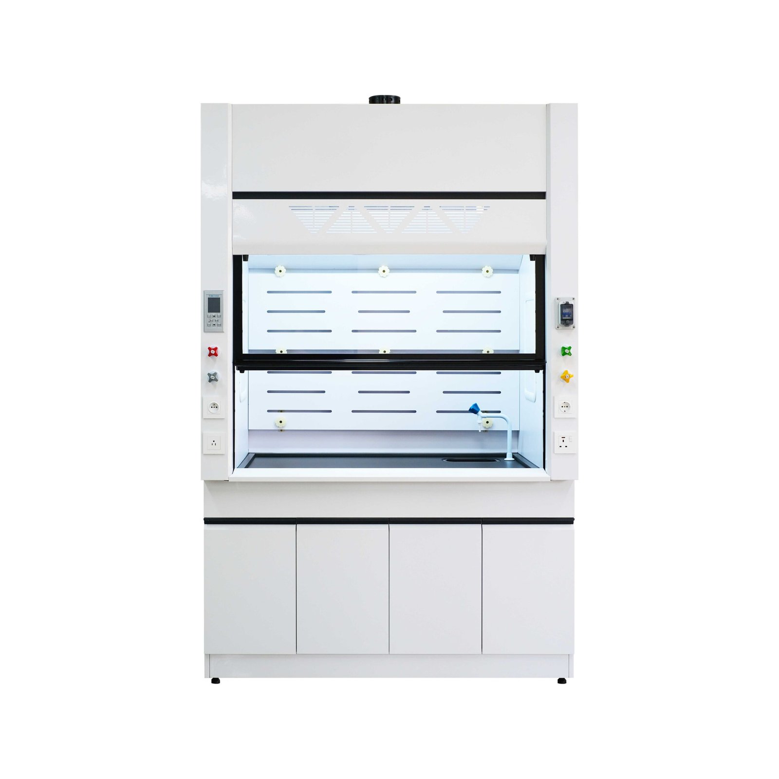
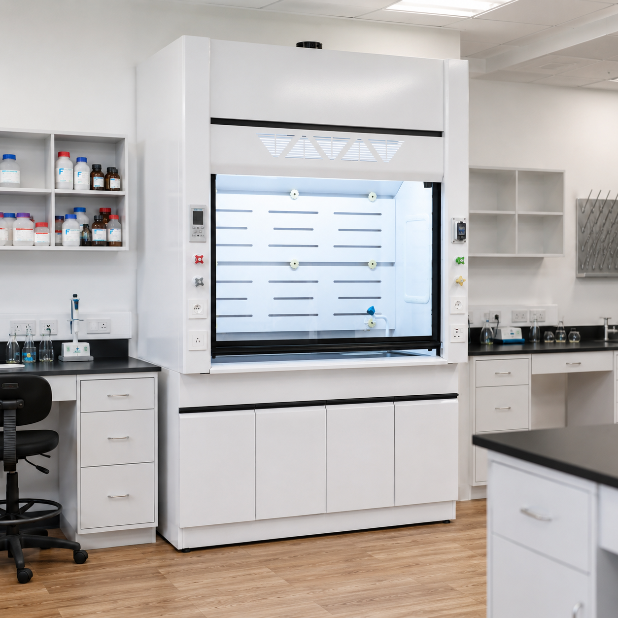
A general purpose steel fume hood provides a ventilated work chamber for routine laboratory operations that can release hazardous or objectionable vapors. Room air enters through the sash opening, passes across the work zone and leaves through a ducted exhaust connection. The building exhaust system then carries the contaminated air to the approved discharge or treatment point.
Product Overview
What This General Purpose Steel Fume Hood Is
The general purpose fume hood family combines a powder-coated steel outer cabinet with a vertical sash, rear baffle system, work surface and exhaust collar. The outer steel shell provides the structural enclosure and service zones. The liner, baffle, work surface, fixtures and other exposed components are selected separately because they face different combinations of chemicals, heat, spills and cleaning agents.
The hood is intended for ducted chemical ventilation rather than filtered recirculation. Reference widths of 1200, 1500 and 1800 mm cover common laboratory layouts, while the internal work zone, services, base arrangement and exhaust connection can be adjusted to the apparatus and room plan.
Hood Body And Exhaust-System Boundary
The hood contains the source and directs contaminated air toward the exhaust connection, but it does not create reliable containment without the rest of the ventilation system. Sash position, exhaust volume, available static pressure, duct resistance, room make-up air and control response all affect performance at the opening.
The quotation therefore identifies whether it covers the hood body alone or also includes the base cabinet, fan, ductwork, airflow monitor, CAV or VAV controls, room-pressure coordination and exhaust treatment. These components can be supplied as a coordinated package, but they are not implied unless listed in the supply schedule.
Product Selection Summary
A general purpose fume hood is the practical starting point for routine wet chemistry, reagent preparation, sample treatment and similar laboratory work when the chemical and temperature exposure can be handled by the selected liner, baffle and work surface. It should not be selected from the word "general" alone. The process inventory and exhaust conditions still determine the final construction.
When to Choose a General Purpose Fume Hood
- The process produces vapors, gases, odors or light airborne contamination that should be captured and discharged through a building exhaust system.
- A painted-steel outer cabinet is suitable for the room environment, while the internal liner and work surface can be matched to the chemical exposure.
- The apparatus fits a conventional benchtop work chamber and does not require the full floor-level clearance of a walk-in hood.
- The laboratory can provide the required exhaust volume, static pressure, make-up air and a suitable discharge or treatment arrangement.
- The project can verify airflow and functional operation after the hood, ductwork, fan and controls are installed.
Select A Different Hood When
Use a special-purpose configuration when the process creates hazards that a routine steel hood is not designed to address. Perchloric-acid work can require a dedicated wash-down hood and exhaust path. High-temperature acid digestion, hydrofluoric-acid exposure, radiochemical work and hazardous-location electrical requirements each change the materials, internal geometry, services or compliance review.
A polypropylene, FRP or stainless-steel fume hood may also be a better fit when corrosive exposure extends beyond the work chamber to the cabinet, base or surrounding room. A ductless hood is a separate choice that depends on filter compatibility, chemical quantity and change-out management; it is not an interchangeable version of this ducted product.
Information Needed Before Selection
The first technical review should include the chemical list and concentration, operating temperature, expected vapor and heat release, apparatus dimensions, preferred working opening, proposed hood width, duct route and available static pressure. Add the required utilities, base-cabinet type, airflow-control strategy, room-pressure requirement and any exhaust-treatment obligation.
These inputs establish whether the general-purpose family is appropriate and reveal the fields that remain project-specific. They also prevent a nominal cabinet width from being approved before the usable chamber, sash access and exhaust demand have been checked together.
Key Specifications And Reference Sizes
Core Configuration
| Selection Field | Available Configuration | Project Check |
|---|---|---|
| Product type | Ducted benchtop general purpose fume hood | Confirm process suitability |
| Exterior cabinet | Powder-coated cold-rolled or galvanized steel | Confirm substrate, thickness and finish |
| Liner and baffle | Phenolic, FRP, PP, stainless steel or another compatible system | Select from chemistry and heat load |
| Work surface | Epoxy resin, phenolic resin, ceramic or stainless steel | Review spills, heat and cleaning |
| Front access | Vertical sash with project-defined working opening | Confirm glazing, stops and usable access |
| Exhaust arrangement | Ducted connection to an external exhaust system | Confirm collar, airflow and static pressure |
| Reference width series | 1200 / 1500 / 1800 mm | Custom dimensions available |
| Airflow control | CAV, two-state or VAV package available | Define sensor, alarm and BMS scope |
| Utilities and accessories | Service fixtures, cup sink, outlets, lighting, monitor and base cabinet | List each required item |
Reference Width And Airflow Planning Table
The following configurations provide a consistent starting point for room planning and exhaust discussions. They are reference arrangements for a made-to-order product, not fixed performance values. The approved technical schedule replaces them after the sash opening, internal materials, duct path and site pressure have been confirmed.
| Nominal Width | Reference Overall Size (W × D × H) |
Reference Chamber Size (W × D × H) |
Reference Exhaust Volume | Planning Use |
|---|---|---|---|---|
| 1200 mm | 1200 × 850 × 2350 mm | 960 × 680 × 1150 mm | 700-1300 m³/h | Compact apparatus |
| 1500 mm | 1500 × 850 × 2350 mm | 1260 × 680 × 1150 mm | 900-1700 m³/h | General laboratory work |
| 1800 mm | 1800 × 850 × 2350 mm | 1560 × 680 × 1150 mm | 1300-2100 m³/h | Larger apparatus or added clearance |
How To Interpret The Reference Values
Width does not determine airflow by itself. The open sash area and selected face-velocity criterion set the initial exhaust requirement; duct losses, baffle setting, room air movement and the chosen control method then affect the duty at the hood connection. The reference range is useful for early fan and duct discussions, but the project schedule must pair each airflow value with a defined sash opening and available static pressure.
The chamber dimensions should also be checked against the apparatus rather than treated as storage volume. Leave clearance for air to move around equipment, keep heat and vapor sources inside the capture zone and preserve access to service fittings, baffles and removable panels.
Construction And Material Selection
Painted Steel Exterior And Double-Wall Service Zones
The steel outer cabinet provides the structural frame, front posts, top enclosure and service-access zones. A chemical-resistant powder coating protects the exposed exterior surfaces in the laboratory environment. The double-wall arrangement also creates routes for plumbing and electrical services without placing their connections directly in the work chamber.
Painted steel describes the outer construction, not every surface touched by the process. The finish, substrate and sheet thickness are confirmed for the order, while panels that require routine service remain removable after installation.
Liner, Baffle And Work-Surface Selection
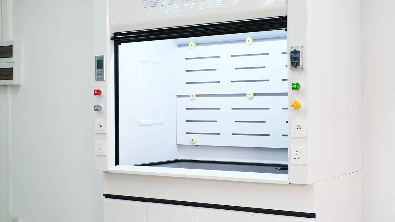
The liner, rear baffles and work surface require separate material decisions because they face the highest chemical, thermal and spill exposure. Phenolic, FRP, PP and stainless-steel liner systems cover different combinations of acids, bases, solvents, cleaning agents and heat. Epoxy resin, phenolic resin, ceramic and stainless steel provide corresponding work-surface choices.
Material selection should follow the complete chemical list rather than the most familiar reagent. Include concentration, temperature, contact duration, mixed vapors, likely spills and the cleaning method. A compatible liner does not compensate for an unsuitable work surface, drain, gasket, service fitting or downstream exhaust component.
Rear Baffle Arrangement
The rear baffle system divides extraction across the lower, middle and upper parts of the work chamber. This helps remove heavier vapors near the work surface while also drawing warm or buoyant contaminants from higher in the enclosure. Removable or adjustable baffles improve cleaning and allow the internal arrangement to be coordinated with the intended process.
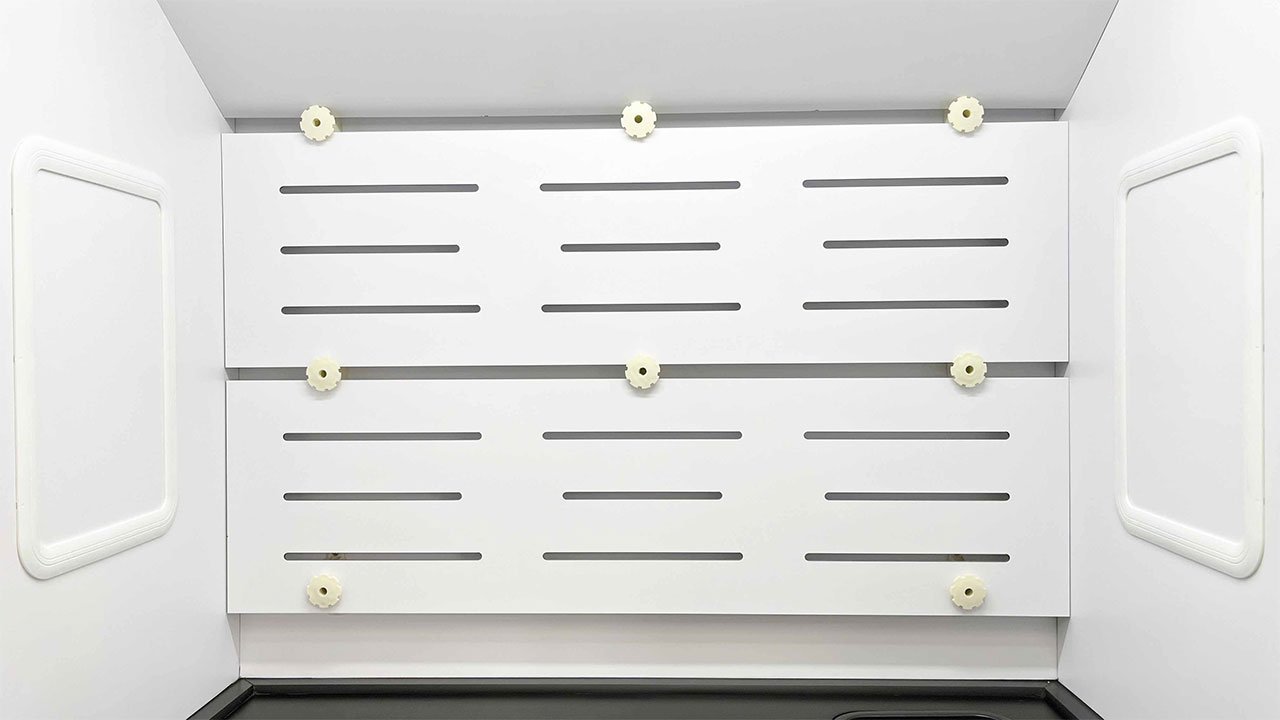
Large apparatus must not seal against the baffle or block its lower openings. The equipment layout should leave a clear route from the sash opening, around the process and into the rear extraction zones.
Sash, Airfoil And Service Access
The vertical sash gives direct access to the work area and forms a movable barrier between the operator and the process. The approved drawing defines the glazing material, full opening, normal working opening, stops and counterbalance arrangement. A lower airfoil guides incoming air over the front edge of the work surface and helps reduce the disturbed zone at the sill.
Service valves, electrical outlets, lighting and monitor controls can be placed on the front posts or service panels. Their quantity, voltage, connection type and chemical exposure must be scheduled before manufacture. Cup sinks and drains should be included only when the process and waste-handling plan require them.
Airflow, Exhaust And Control Integration
Airflow Path Through The Hood
Air enters through the sash opening and any designed bypass path, moves across the work zone and is collected through the rear baffle openings. It then passes to the top plenum and exhaust collar. The hood shapes this path, while the fan and duct system provide the pressure difference that keeps air moving away from the operator.
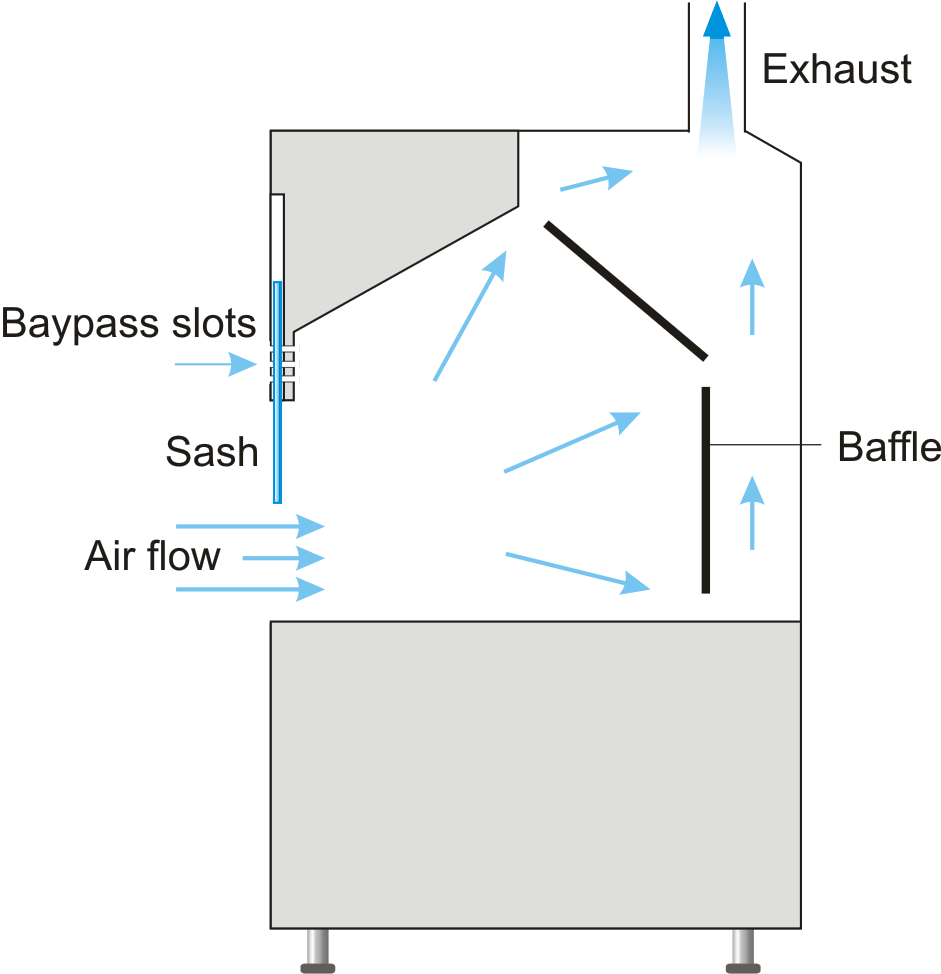
The diagram explains the operating path rather than a guaranteed airflow pattern for every installation. Equipment position, cross-drafts, open doors, supply-air diffusers and users moving near the sash can change local flow. The installed hood must therefore be evaluated in its actual room.
Face Velocity, Sash Opening And Static Pressure
Face velocity is meaningful only when paired with the sash opening at which it is measured. Increasing the open area at the same velocity raises the required exhaust volume. Closing the sash reduces the open area, but the control system must prevent unstable velocities, excessive noise or room-pressure problems.
Static pressure at the exhaust collar must be sufficient to overcome the hood, duct fittings, treatment equipment and discharge losses at the scheduled airflow. A fan selected only from nominal cabinet width can miss the real duty. Provide the duct route and operating points so airflow and pressure can be evaluated together.
Hood, Fan, Ductwork And Treatment Boundary
| System Element | Technical Role | Scope To Confirm |
|---|---|---|
| Fume hood body | Contains the source and directs air to the collar | Cabinet, liner, sash, baffles, work surface and services |
| Exhaust fan | Provides airflow and pressure for the complete path | Fan duty, materials, motor, VFD and weather arrangement |
| Ductwork | Carries contaminated air to treatment or discharge | Material, size, route, fittings, drainage and access |
| Make-up air | Replaces exhausted room air without disturbing capture | Diffuser location, room balance and simultaneous operation |
| Airflow controls | Monitor or adjust airflow as sash or operating mode changes | Sensor, alarm, air damper, controller and BMS signals |
| Exhaust treatment | Reduces selected contaminants before discharge | Need, chemistry, removal target, pressure loss and waste handling |
CAV, Two-State And VAV Options
A constant-air-volume system operates around one scheduled exhaust condition. A two-state arrangement switches between two defined duties, such as occupied and setback operation. A VAV system changes exhaust flow in response to sash position, face velocity or another approved control input. The appropriate choice depends on the number of hoods, room-pressure strategy, energy objective and required response.
Controller display, air-damper position or fan command does not by itself prove that the required airflow is present. Define the measurement method, alarm points, emergency mode, BMS interface and site acceptance test. Where several hoods share an exhaust system, include simultaneous diversity and room supply/exhaust tracking in the control review.
Applications, Fit And Product Selection
Suitable Routine Laboratory Work
A general purpose steel fume hood is commonly selected for reagent preparation, sample transfer, wet-chemistry procedures, solvent handling and analytical work that produces vapors or odors within the limits of the chosen materials. It can serve research, quality-control, healthcare, industrial and teaching laboratories when the process is compatible with a conventional ducted enclosure.
The building type does not establish suitability. A school hood and an industrial quality-control hood may share the same cabinet size while requiring different services, operating schedules, chemicals and control sequences. Selection should remain tied to the process, apparatus and room ventilation.
Conditions Requiring A Special-Purpose Hood
Do not extend a general-purpose configuration to every chemical process. Perchloric acid can require a dedicated wash-down design and compatible exhaust path. Hot, concentrated acid digestion can require different liner, work-surface and duct materials. Hydrofluoric-acid work requires a glass-free compatibility review. Radioisotope procedures can introduce seamless construction, decontamination and monitoring requirements. Flammable-vapor work may require a project-specific hazardous-location electrical design.
These conditions should be identified before the cabinet is quoted. Adding a different liner after the airflow system, services and internal geometry have already been selected may not create a suitable special-purpose hood.
Configuration And Customization Sequence
- Define the process. List chemicals, concentrations, temperatures, vapor release, heat load, operating duration and cleaning method.
- Fit the apparatus. Record equipment width, depth and height together with service connections, access movements and the clear space needed around it.
- Select exposed materials. Choose the liner, baffles, work surface, drain, sash glazing, fixtures and duct materials from the complete exposure list.
- Set the working opening. Define the normal sash position, full access requirement and any sash stop or automatic-sash function.
- Calculate exhaust duty. Pair the working opening and design criterion with available static pressure, duct losses, fan duty and room make-up air.
- Choose controls and alarms. Decide between CAV, two-state or VAV operation and define monitoring, emergency mode, BMS points and acceptance measurements.
- Lock the supply schedule. Identify the hood, base, fan, ductwork, treatment, utilities, controls, installation and commissioning responsibilities.
Available Configuration Options
Project options include custom external and internal dimensions, alternative liner and work-surface materials, base cabinets, service fixtures, cup sinks, drains, electrical outlets, lighting, airflow monitors, sash stops and control packages. Exhaust-collar size and position can be coordinated with the approved duct drawing.
Options should solve a defined process or installation need. For example, a wider cabinet should provide necessary apparatus clearance, not simply a larger nominal product. A sink should have an approved drainage path, and an airflow monitor should match the sensor and alarm functions in the control schedule.
Information Required For Quotation
For each hood tag, provide the chemical list, concentration and temperature; process and apparatus description; required external and internal dimensions; normal and maximum sash opening; liner and work-surface preference; exhaust airflow and static pressure; duct route; service fixtures; electrical supply; base cabinet; airflow-control sequence; room-pressure requirement; quantity and destination. Include the laboratory layout, reflected ceiling plan and exhaust schematic when available.
The returned technical schedule should identify the proposed dimensions, materials, exhaust connection, planning airflow, controls, accessories, supply boundary and unresolved project items. Those approved fields define the delivered hood more accurately than the family-page reference values alone.
Installation, Commissioning And Maintenance
Pre-Installation Coordination
Confirm the delivery route, floor loading, bench or base support, wall and ceiling clearance, exhaust-collar position, duct support, fan location, service entries and access to removable panels before the hood arrives. The room supply-air pattern should be reviewed at the same time because high-velocity diffusers, doors and traffic close to the sash can disturb capture.
The hood should be level and secured without twisting the cabinet or sash guides. Duct connections must not impose structural load on the exhaust collar. Water, gas, electrical and drainage work should follow the approved utility schedule, local requirements and the material compatibility established for the process.
Airflow And Functional Acceptance
After the hood, ductwork, fan and controls are complete, verify exhaust airflow and static pressure at the defined operating conditions. Check sash movement, lighting, service fixtures, monitor display, alarms, emergency mode and any CAV or VAV response. Where the room uses pressure control, test the hood together with the supply and general exhaust systems.
Airflow readings should record the sash opening, fan condition and control mode. Smoke visualization or other site procedures can help identify reverse flow and disturbances, but the required acceptance method belongs to the project specification and applicable local rules. A factory reference value does not replace installed-system verification.
Operation, Inspection And Documentation
Keep the sash at the designated working position and place apparatus far enough inside the enclosure to preserve capture around it. Do not use the work chamber for permanent chemical storage or block the rear baffle openings. Large equipment may need to be raised so air can move beneath and around it.
Routine inspection should cover the sash and counterbalance, airfoil, liner joints, work surface, baffles, fixtures, drains, monitor, alarms, duct connection and visible corrosion or coating damage. Recheck airflow after fan, duct, control or room-ventilation changes and after moving large apparatus into the hood.
Keep the approved drawing, material schedule, exhaust duty, control sequence, acceptance record and maintenance instructions with the hood tag. These documents preserve the basis of selection and make later changes easier to evaluate.
Related Laboratory Fume Hoods
Compare the polypropylene fume hood when corrosive exposure calls for welded PP construction throughout the cabinet, the FRP fume hood when fiberglass-reinforced construction fits the chemical and structural requirement, or the stainless steel fume hood when cleaning, durability or process conditions justify a stainless cabinet. Review the full laboratory fume hood range before selecting a cabinet for a special-purpose process.
Dedicated pages for the perchloric acid fume hood, acid digestion fume hood, radioisotope fume hood and explosion-proof fume hood address process-specific construction and system requirements that should not be added casually to a general-purpose hood.
Frequently Asked Questions
What Is A General Purpose Fume Hood?
It is a ducted laboratory enclosure for routine chemical operations that release vapors, gases, odors or light airborne contamination. It draws room air through a controlled sash opening and sends the contaminated air to an external exhaust system.
Is A Steel Fume Hood Made Entirely From Steel?
No. "Steel" describes the outer cabinet in the general purpose fume hood family. The liner, baffles, work surface, sash, fixtures, drains and exhaust components can use different materials selected for their actual exposure.
Which Widths Are Available?
Reference widths are 1200, 1500 and 1800 mm. External dimensions, chamber clearance, base arrangement and service positions can be adjusted for the apparatus and laboratory layout.
How Much Exhaust Air Does The Hood Require?
The requirement depends on hood width, working sash opening, design criterion, duct losses and available static pressure. Reference planning ranges are 700-1300, 900-1700 and 1300-2100 m³/h for the three width series, but the project schedule must confirm the operating point.
Are The Exhaust Fan And Ductwork Included?
Only when they appear in the quotation. The hood can be supplied alone or with a coordinated fan, ductwork, airflow controls and exhaust-treatment package. The supply schedule identifies the boundary at each connection.
Can The Hood Use VAV Control?
Yes. CAV, two-state and VAV packages are available. A VAV configuration requires a defined control input, airflow measurement or verification method, compatible air damper and fan strategy, alarms and commissioning procedure.
Can It Be Used For Perchloric Acid Or Hot Acid Digestion?
Not as an unmodified general-purpose configuration. These processes can require dedicated internal materials, geometry, wash-down, drainage and exhaust components. Select the corresponding special-purpose hood after reviewing the chemical and temperature conditions.
What Information Is Needed To Prepare A Quotation?
Provide the chemical list, concentrations, temperatures, apparatus dimensions, preferred hood size and sash opening, available airflow and static pressure, liner and work-surface requirements, utilities, controls, base cabinet, quantity, destination and laboratory or CAD layout.
Contact The Xicheng Engineering Team Today
Send us your chemical list, operating temperatures, apparatus dimensions, preferred hood width, working sash opening, available airflow and static pressure, required utilities, and laboratory layout or CAD drawings. We will prepare a material-specific general purpose fume hood configuration, exhaust-integration proposal and quotation within 24 hours.
Shenzhen Office: No. 34 Zhenxing Road (Shengtaian Heavy Industrial Park B), Loucun, Guangming New District, Shenzhen, Guangdong, China
WhatsApp: +86 181 2647 8161
Engineering Mailbox: fanalax34@gmail.com