


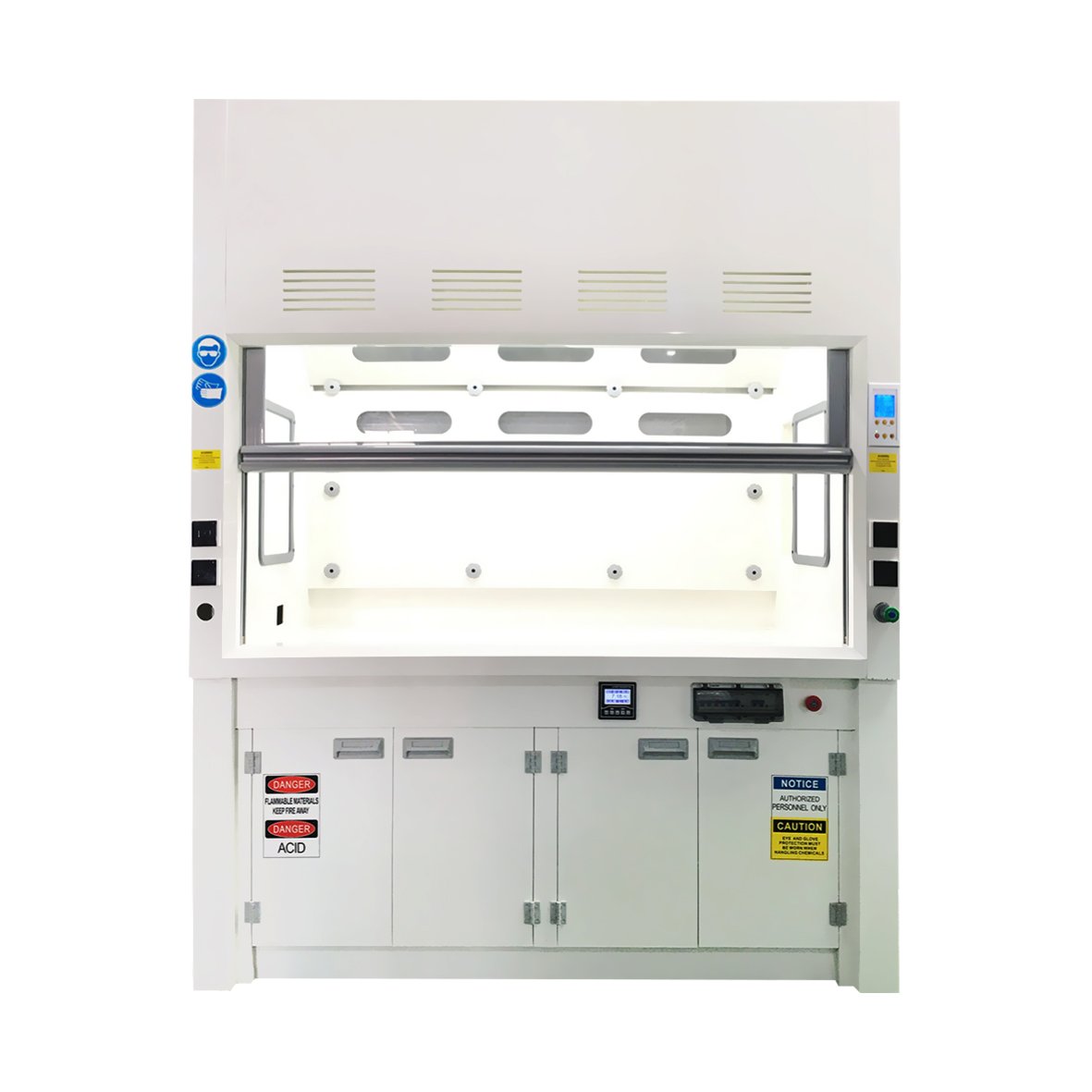
Description
Perchloric Acid Fume Hood for Dedicated Wash-Down Exhaust
A perchloric acid fume hood is a special-purpose laboratory enclosure designed around the risks created when perchloric-acid vapor or mist can condense on the hood and exhaust surfaces. It combines a cleanable work chamber with a defined water-wash path, controlled collection and drainage, and an independent exhaust interface. These elements are selected together because changing only the visible liner does not address deposits that can form behind the baffle, in ductwork or near the exhaust fan.
XICHENG configures the hood for the documented process and facility. The project schedule defines the perchloric-acid concentration, temperature, quantity, operating frequency and heating condition; apparatus and working opening; interior and exposed-component materials; wash-water coverage and controls; trough and drain path; duct, fan and discharge arrangement; airflow monitoring; and the division of supply among the equipment manufacturer and site contractors.
What Is
The perchloric acid fume hood is a made-to-order wash-down hood and a set of controlled interfaces to the building systems. Inside the enclosure, smooth coved or continuously welded surfaces, an accessible baffle zone, spray piping, a collection trough and a drain connection support washing and inspection. Outside the enclosure, the water supply, wastewater route, dedicated duct and exhaust fan must continue the approved system design.
The final supplied boundary can vary by project. One order may include the hood, wash piping, drain connection and control valve while the mechanical contractor supplies the dedicated duct and remote fan. Another may require a more coordinated package with duct wash components, airflow monitoring and controls. The quotation and approved drawings must identify every included component and every site-provided interface so that no section between the hood collar and final discharge is assumed.
Reference widths and exhaust-volume directions can support early room planning, but they do not determine the installed system by themselves. The working opening, apparatus arrangement, duct route, pressure loss, fan selection, wash-water conditions and drainage design must be closed before manufacture and commissioning.
Why Perchloric Acid Requires a Dedicated Design
When perchloric acid is heated or otherwise released as vapor or mist, residues can collect on unsuitable hood and exhaust surfaces. Contact with some metals or other materials can create shock-sensitive perchlorate deposits. This is why heated perchloric-acid procedures should not be moved into a conventional fume hood merely because its visible chamber appears corrosion resistant.
The dedicated design reduces locations where residue can remain and provides a controlled method for washing the applicable surfaces. Rounded or coved transitions, accessible baffles, a watertight collection zone and a defined drain route make inspection and cleaning more practical. Wash nozzles must cover the approved path rather than only the front chamber, and the duct arrangement must support drainage and access instead of creating hidden horizontal pockets.
An independent exhaust route prevents the perchloric-acid stream and wash system from being treated as a branch of ordinary manifold exhaust. The mechanical design must specify the duct material, geometry, inspection openings, remote fan and discharge conditions. Airflow and wash readiness are separate operating conditions: adequate exhaust does not prove that spray coverage and drainage are available, and an active wash circuit does not prove that the hood maintains its required inward airflow.
Product Selection Summary
A perchloric fume hood should be selected when the documented procedure can release perchloric-acid vapor or mist and the project can provide a complete wash-down, drainage and independent exhaust arrangement. The decision is driven by the process and the full exhaust path, not by cabinet material or hood width alone. Use the conditions below to establish whether the perchloric acid fume hood family fits the work before dimensions, airflow and component materials are finalized.
When to Choose a Perchloric Acid Fume Hood
- Perchloric acid will be heated, evaporated, digested or otherwise handled under conditions that can carry vapor or mist into the hood and exhaust system.
- The hood interior, baffle zone and applicable exhaust surfaces can be included in a defined wash-coverage schedule.
- Wash water can be collected through a watertight work zone, rear trough and controlled drain route without allowing residue-bearing liquid to accumulate.
- The facility can provide an individual, non-manifold duct and fan route from the hood connection to the final discharge point.
- Materials can be reviewed component by component against the acid concentration, temperature, co-used chemicals, cleaning agents and expected exposure.
- The project team can coordinate plumbing, ductwork, fan, electrical supply, controls, wastewater handling, commissioning and operating procedures as one system.
Key Product-Family Data
The available configuration is a made-to-order perchloric acid hood with a cleanable interior, accessible baffle zone, wash piping, collection and drain interfaces, and a dedicated exhaust connection. A three-width reference series provides a starting point for laboratory planning. The selected width does not establish the sash opening, exhaust requirement, duct size or wash-water demand; those values depend on the apparatus, operating opening and approved system design.
The project schedule must identify the material and construction of each exposed part, including the work surface, liner, baffle, sash components, fasteners, seals, trough, drain, duct and fan. A general label such as stainless steel or corrosion resistant is not a complete material specification. The wash system also requires a defined supply condition, control method, coverage zone and drainage endpoint. The approved equipment schedule and drawings state which components are supplied with the hood and which are completed on site.
Do Not Select It from Material or Product Name Alone
Do not specify the wash-down fume hood only because a tender calls for a stainless-steel hood, an acid hood or a wash-down enclosure. The perchloric-specific decision requires the process risk, cleanable geometry, wash coverage, drain path and dedicated exhaust arrangement to be confirmed together. A conventional hood fitted with a spray bar is not equivalent if residue can remain in an inaccessible baffle, horizontal duct section or unwashed fan connection.
For hot corrosive work that does not involve perchloric acid or perchlorate-deposit control, evaluate an acid digestion fume hood. When chemical resistance of the cabinet is the primary issue and no dedicated perchloric wash system is required, a polypropylene laboratory fume hood or stainless steel laboratory fume hood may be more appropriate. None of these alternatives should be used for heated perchloric-acid work unless the complete special-purpose system has been evaluated and approved for that process.
Do not assume that a wet scrubber or recirculation package is part of the standard hood. Gas treatment and wastewater treatment are separate engineering decisions. They may be added when the process, discharge requirement and approved responsibility boundary call for them, but they do not replace washable exhaust surfaces or the independent duct route.
Key Specifications and Reference Configurations
The values in the first table are reference planning configurations for comparing cabinet and chamber envelopes. They are not a stock-size guarantee or a substitute for the project airflow calculation. The approved drawings, component schedule, wash-system design and mechanical calculations govern the manufactured hood and its building interfaces.
Reference Planning Configurations
| Nominal Width | Reference Overall Size, W x D x H | Reference Chamber Size, W x D x H | Reference Exhaust-Volume Range |
|---|---|---|---|
| 1200 mm | 1200 x 1100 x 2350 mm | 1000 x 650 x 1150 mm | 700-1300 m3/h |
| 1500 mm | 1500 x 1000 x 2350 mm | 1300 x 650 x 1150 mm | 900-1700 m3/h |
| 1800 mm | 1800 x 1100 x 2350 mm | 1600 x 650 x 1150 mm | 1300-2100 m3/h |
These ranges are useful for early space, utility and exhaust planning only. Final external dimensions, usable chamber, clear sash opening, exhaust volume, face-velocity criterion, static pressure, collar size and fan duty must be calculated for the approved apparatus arrangement and operating opening, then verified under the agreed commissioning conditions.
Compare Hood Size, Chamber and Working Opening Separately
Nominal width identifies the general cabinet class, not the complete usable envelope. Side-wall build-up, service chases, wash piping and the baffle reduce the clear internal space. A large apparatus may fit through the room doorway but still interfere with the sash travel, rear baffle, spray path or drain trough after installation. Provide the apparatus width, depth, height and service clearances before selecting the hood size.
The chamber dimensions also do not define the operating opening. The sash arrangement and permitted working position influence the required exhaust volume and the operator’s reach. A design review should identify the normal working opening, maximum setup opening and closed or standby position, together with any stop, alarm or airflow-control sequence. The opening used for airflow calculation must match the opening used during acceptance testing.
Allow separate clearance for the exhaust collar, vertical duct route, water and drain connections, electrical service and access to removable baffles or inspection points. Space above and behind the cabinet should support maintenance without forcing a horizontal duct pocket or concealed plumbing joint. Building access, finished ceiling height, base-cabinet arrangement and floor or wall penetrations must be coordinated before the approved drawing is released.
Wash-Water, Drain and Exhaust Interfaces
The water inlet is a process interface, not an ordinary convenience tap. The project must define the available pressure and flow, water quality, isolation valve, activation method, controls and any backflow or building-plumbing requirements. No universal inlet pressure, nozzle count or wash duration can be assigned before the coverage zones and duct arrangement are known.
The drainage path begins at the wash collection surfaces and continues beyond the hood connection. The design must identify trough geometry, drain size, slope, receiving line, inspection access and wastewater destination. The facility also decides whether segregation, neutralization or another treatment step is required. A drain connection on the cabinet does not by itself confirm that the downstream route is suitable.
The exhaust interface must be sized with the duct and fan. Confirm collar dimensions, duct material, vertical or self-draining routing, inspection points, system resistance, fan location and discharge. The hood cannot generate airflow on its own, and an exhaust-volume reference does not establish the available static pressure. Fan duty and control behavior must be based on the installed route and the agreed sash condition.
Wash-Down Construction and Drainage
The wash-down system must reach the surfaces included in the approved perchlorate-deposit control plan and move the resulting liquid into a controlled drain route. Cabinet material, spray nozzles and a drain connection are necessary design fields, but none is sufficient on its own. Interior geometry, component materials, spray coverage, collection and downstream wastewater handling must work as one cleanable path.
Coved Interior and Component-Level Materials
The work chamber should minimize ledges, open seams and inaccessible corners where residue can remain. Coved transitions, continuously welded joints and a watertight collection zone make washing and visual inspection more practical. The baffle should be removable or otherwise accessible without creating concealed areas that cannot be reached by the approved wash or maintenance method. Utility penetrations and fastener locations should be limited and detailed so that liquid cannot enter an uninspectable cavity.
Type 316 stainless steel is a common construction direction for a perchloric acid hood, but a grade name is not a universal compatibility statement. The work surface, liner, baffle, sash frame, fasteners, seals, trough, drain, spray piping, nozzles, duct and fan may experience different chemical, thermal and mechanical conditions. Each exposed component must be reviewed against the process concentration, temperature, co-used substances and cleaning method.
Surface finish and joint construction matter alongside the base material. A nominally resistant sheet can still create a poor wash path if joints trap liquid, welds are unfinished, dissimilar metals are exposed or replaceable parts interrupt drainage. The approved material schedule should identify both material and construction for the complete exposed path rather than describing only the visible liner.
Define the Complete Wash Coverage
Wash coverage begins in the hood chamber and continues through every applicable surface where vapor, mist or residue may travel. The schedule should identify the work-zone walls, baffle face and rear zone, exhaust transition, collar, duct sections and fan-side components that are included. It should also identify surfaces that are not washed and explain how they remain accessible for inspection or cleaning.
Nozzle presence does not prove coverage. Spray direction, shadowed areas, pipe location, duct geometry and available water conditions determine where liquid actually reaches. A front chamber that becomes visibly wet may still leave a dry baffle cavity or duct section. Coverage should therefore be reviewed from the hood connection through the approved exhaust route and checked under the installed water conditions.
Wash Piping, Valves and Controls
The wash circuit may include an inlet connection, isolation and control valves, distribution piping, spray devices and status or control interfaces. The final arrangement depends on whether the supplied scope ends at the cabinet or continues into duct and fan wash components. Water pressure, flow, quality, nozzle pattern, activation method and sequence must be defined for the approved geometry rather than taken from a generic cabinet specification.
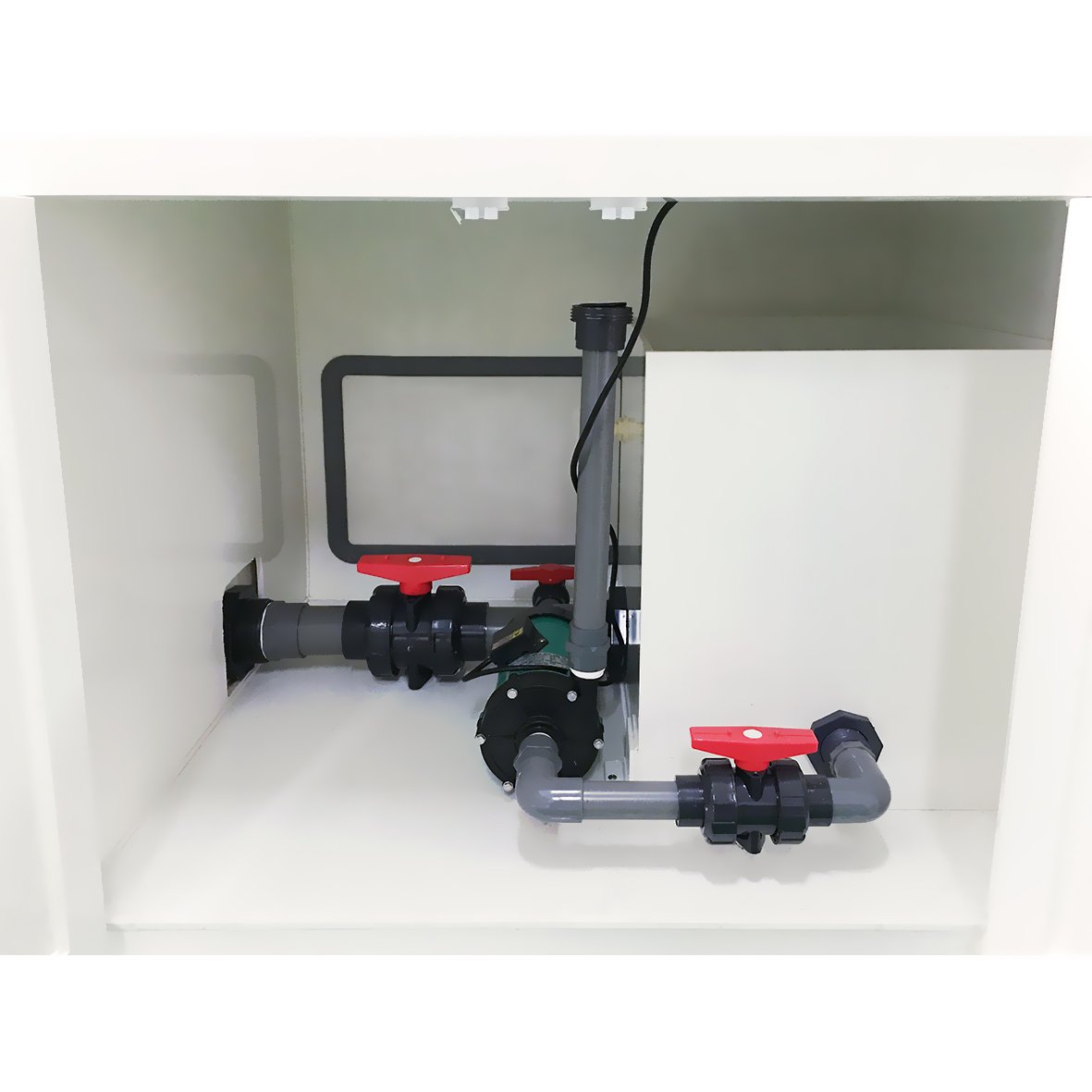
The illustrated arrangement helps identify the interfaces that must be coordinated, but it does not establish one mandatory circuit. It does not confirm final pipe materials, inlet pressure, flow, valve logic, reservoir need or supplied boundary. The project wash schematic must state which components are included, how the circuit is isolated and activated, and how the operator confirms that the required sections receive water.
Manual activation may be suitable for one operating procedure, while another project may require controlled sequencing, status indication or interlocks. The facility must define who is permitted to initiate a wash, what operating conditions are required, how exhaust remains available during the sequence and how an unavailable water supply is communicated. The control design should avoid implying that an energized valve proves successful spray coverage.
Collection Trough, Drain and Wastewater Route
Wash water must move from the wetted surfaces to a defined collection point without pooling in the chamber or exhaust path. A watertight work zone, rear collection trough and correctly located drain connection support this movement. Slope, transitions and penetrations should be reviewed on the approved drawing so that liquid is directed toward the drain and does not remain behind the baffle or in a duct low point.
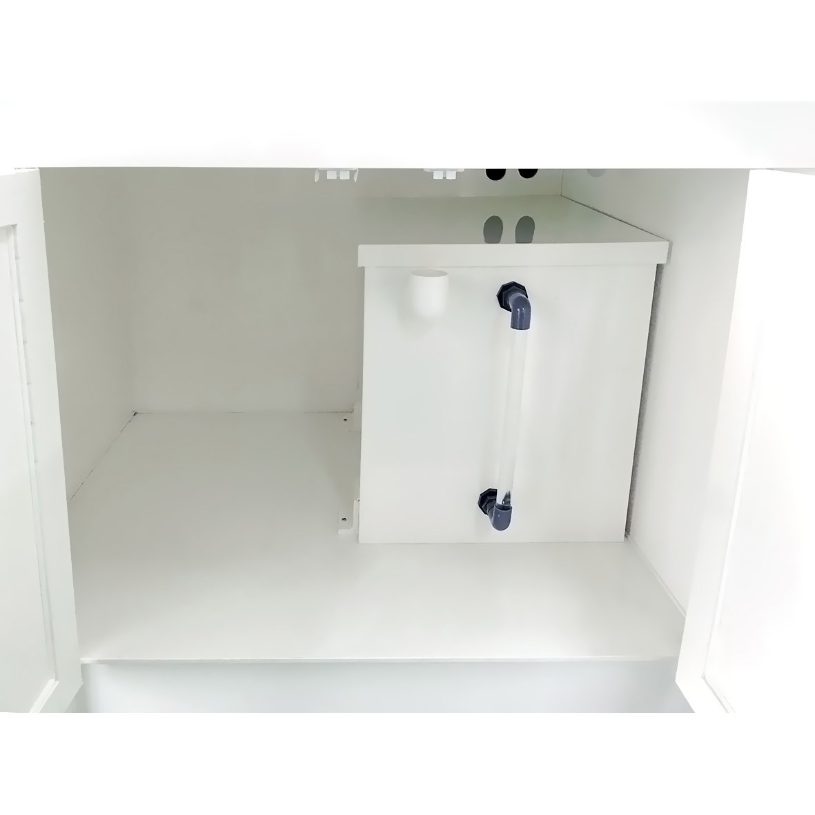
The image shows a possible internal piping and collection arrangement, not proof of complete hood-to-stack coverage. It does not define the final drain geometry, receiving line, treatment requirement or wastewater destination. Those fields remain on the plumbing and wastewater plan, and the receiving system must be ready before a functional wash test is performed.
Drainage responsibility continues beyond the equipment connection. The project team must identify the downstream pipe material, slope, separation from incompatible wastes, inspection access and destination. Local facility and regulatory requirements determine whether collected liquid can enter a treatment system, requires segregation or needs another approved disposal route. The hood drain must not be connected by assumption.
| Wash or Drainage Area | Design Information to Confirm | Functional Check |
|---|---|---|
| Work chamber and baffle | Cleanable geometry, material, access and intended spray zones | Observe wetting of specified accessible surfaces and inspect shadowed areas |
| Collar, duct and fan path | Included wash sections, routing, low points and inspection access | Confirm coverage and free drainage for the installed geometry |
| Water supply and controls | Pressure, flow, quality, isolation, activation, sequence and status | Operate controls and verify water reaches the defined circuit |
| Collection trough and drain | Slope, connection, seal, downstream pipe and wastewater destination | Check for leakage, pooling, blockage and uncontrolled discharge |
Dedicated Exhaust and Airflow Integration
The perchloric acid hood, duct and exhaust fan must be engineered as one independent air path. The hood connection is only the starting point: duct geometry, drainage, inspection access, system resistance, fan construction and final discharge all affect whether the installed system can maintain the intended inward airflow while remaining accessible for washing and inspection.
Why the Exhaust Path Must Remain Independent
An individual exhaust route prevents the perchloric-acid stream from entering an ordinary shared manifold where deposits could reach branches and equipment that are not designed for the process. It also gives the project a defined boundary for material selection, wash coverage, drainage and maintenance. The independent route should continue from the hood collar through the dedicated duct and fan to the approved discharge point.
Isolation is a system condition, not merely a separate collar on the cabinet. Connecting that collar to a common riser would reintroduce shared surfaces and uncertain flow interactions downstream. The mechanical design should therefore identify the complete route, every connection, access point, fan location and discharge condition before the hood and exhaust equipment are released.
The dedicated path does not remove the need to coordinate laboratory pressure and replacement air. Exhausting the hood changes room airflow and can affect doors, neighboring enclosures and building pressure relationships. The air-balance design must provide suitable make-up or supply air without directing disruptive cross-drafts across the sash opening.
Duct Geometry, Drainage and Inspection Access
Routing should minimize horizontal sections and hidden low points where liquid or residue can remain. A vertical or intentionally self-draining path supports wash-water return and reduces stagnant sections, but the actual geometry must be shown on the mechanical drawing. Where offsets cannot be avoided, their slope, collection behavior and access for inspection and cleaning require specific review.
Duct joints, transitions, supports and penetrations should preserve the cleanable path and remain compatible with the selected material system. A nominal duct material does not resolve how seams, flanges, gaskets or dissimilar components behave under the process and wash conditions. The component schedule should identify these details through the fan and any downstream section included in the wash plan.
Inspection openings must be located where the facility can actually reach them after ceilings, services and access panels are installed. Access is particularly important near changes in direction, the hood transition, low points and fan-side components. The design should also allow components to be isolated and serviced without exposing personnel to an uncontrolled exhaust path.
Size the Hood, Duct and Fan as One System
Airflow selection begins with the clear sash opening and the operating condition used for the containment basis. Hood width alone does not determine exhaust volume. The calculation must account for the selected opening, chamber and baffle geometry, duct velocity, fittings, vertical rise, discharge arrangement and the pressure losses of all installed components.
The reference exhaust-volume ranges in the specifications section are planning directions, not fan-selection values. The final fan duty must be based on the calculated airflow and total system resistance at the installed condition. Available static pressure should be stated at a defined point so that the hood, duct and fan schedules use the same reference. Motor, drive, control method and exposed fan materials remain project-selected fields.
Variable or standby airflow may be considered only when the control sequence preserves the required hood condition and remains compatible with the dedicated exhaust and wash procedure. A sash-position signal or damper command is not proof of actual airflow. Any airflow-control strategy should define the measured variable, operating setpoints, alarm conditions, failure response and commissioning method.
Room supply air should be checked at the same time. High-velocity diffusers, open doors or large thermal loads can disturb the opening even when the exhaust fan reaches its scheduled volume. Final acceptance must therefore evaluate the installed hood within the actual room and ventilation condition rather than treating fan airflow as the only evidence.
Airflow Monitoring and Wash-System Status Are Different
An airflow monitor can indicate whether the sensed exhaust or face-velocity condition remains within the configured range. It cannot confirm that water is available, every nozzle is open, all specified surfaces are wetted or the drain is clear. Conversely, a wash-control indication cannot confirm inward airflow or containment at the sash opening.
The control schedule should keep these functions distinct. Airflow status may include a local display, audible or visual alarm and a BMS point. Wash status may include valve command, water-availability indication, sequence status or fault reporting where those functions are supplied. Drainage may require a separate observable check or project-specific sensor. The required signals, alarm delays, response and fail condition should be defined before controls are ordered.
Commissioning should compare the installed airflow with the agreed opening and system condition, verify monitor and alarm behavior, and confirm that room air movement does not undermine the enclosure. Wash and drainage checks are then performed as separate functional tests. Recording each result independently prevents one active indication from being treated as evidence that the complete perchloric-acid exhaust system is ready.
Applications, Suitability and Product Selection
The perchloric acid fume hood family is intended for documented perchloric-acid procedures that require a dedicated wash-down hood and independent exhaust path. Suitability depends on the actual acid condition, apparatus, operating frequency and facility systems. The laboratory name or industry does not establish fit; two rooms performing different procedures may require different hoods even when both describe their work as analytical chemistry.
Good-Fit Perchloric-Acid Work
A good-fit application typically involves perchloric acid being heated, concentrated, evaporated or used in a digestion step that can carry vapor or mist beyond the work chamber. Examples may include sample preparation or analytical procedures where the documented method and facility safety review require a dedicated perchloric fume hood. The procedure, not the example label, controls the selection.
The application should have a stable and reviewable operating envelope. The project team should know the maximum acid concentration and quantity, the operating temperature, the heat source, how often the work occurs and what other materials enter the hood. It should also be possible to define a clear wash procedure, wastewater route, dedicated exhaust path and maintenance responsibility.
The hood is also a better fit when the facility can segregate this work from incompatible general use. Dedicated equipment, posted use restrictions and documented operating procedures help prevent an apparently available enclosure from being used for unrelated work that has not been included in the material and hazard review.
When a Perchloric Acid Fume Hood Is Not a Good Fit
A perchloric acid hood is not the default choice for every hot-acid procedure. When the work uses other corrosive acids and perchlorate-deposit control is not the governing mechanism, an acid digestion fume hood may provide the more appropriate material and heat-management direction. For ordinary chemical ventilation, a general-purpose steel fume hood may be sufficient after the chemical and airflow review.
Do not assign general solvent, flammable-material or mixed-waste work to the perchloric acid fume hood without a separate process review. The presence of a wash system does not establish suitability for combustible materials or incompatible chemical mixtures. The perchloric acid fume hood is also a poor fit when the exhaust must connect to a shared manifold, the duct cannot be inspected or drained, the wastewater destination is undefined, or the facility cannot maintain the specified wash and exhaust systems.
Small quantities or unheated use should still be reviewed through the facility’s risk process rather than assumed to require or not require the wash-down fume hood. The purpose of the selection review is to match the equipment and controls to the documented procedure, not to apply one threshold to every laboratory.
Select the Complete Configuration in This Order
- Define the process. Record concentration, quantity, temperature, heating, duration, frequency, co-used substances and cleaning method.
- Approve the exposed-component materials. Review the work surface, liner, baffle, sash parts, seals, fasteners, trough, drain, duct and fan against the complete exposure.
- Map wash coverage. Identify every hood and exhaust surface to be washed, the access needed to inspect it and the method used to verify wetting.
- Close the drainage path. Define collection, slope, drain connection, downstream pipe, wastewater destination and treatment responsibility.
- Fit the apparatus and opening. Select the cabinet and chamber envelope around the apparatus, working opening, sash movement, utilities and maintenance clearance.
- Calculate exhaust and room air. Determine the airflow basis, duct loss, fan duty, discharge and replacement-air condition for the installed route.
- Define controls and utilities. Close water, power, airflow monitoring, wash control, alarms, BMS and failure-response requirements.
- Assign supply and lifecycle responsibilities. State who provides, installs, tests, operates, inspects and maintains each interface.
Information Needed to Configure the System
Submit the process method or a concise process description, chemical list, apparatus drawing and laboratory layout. Include the desired working opening, room access constraints, available ceiling height and proposed location of water, drain, power and exhaust services. A simple mark-up showing apparatus and utility positions is more useful than a width request without an internal layout.
Provide the mechanical and plumbing basis where available: duct route, fan concept, discharge point, expected room pressure relationship, water conditions, receiving drain and wastewater requirements. Identify control and documentation needs such as airflow indication, local alarms, wash status, BMS points, operator access, inspection ports, acceptance records and training.
XICHENG uses these inputs to prepare a coordinated hood configuration and interface schedule. The returned package should identify the proposed envelope, preliminary material direction, wash and drain arrangement, exhaust connection, controls, optional scope, exclusions and unresolved project fields. Final manufacture and installation should follow the approved project documents after the laboratory, facility and relevant contractors have closed the interfaces.
Installation, Commissioning and Maintenance
A perchloric acid fume hood is ready for service only after the cabinet, wash-water circuit, drainage, dedicated exhaust, room air and controls have been installed and checked as a coordinated system. Delivery of the hood does not close the building interfaces. Installation records should show what was supplied, what was completed on site and which party accepted each functional result.
Coordinate the Building Interfaces
Before delivery, confirm the transport route, doorway and lift dimensions, floor loading, finished ceiling height, final hood position and maintenance clearances. Verify that the base, work surface and cabinet can be leveled and sealed as shown on the approved drawing. Service penetrations should be located without creating hidden liquid paths or obstructing baffle and inspection access.
The mechanical contractor should coordinate the dedicated duct route, supports, joints, access openings, fan, discharge and replacement-air condition. The plumbing scope should identify the water connection, isolation, controls, collection drain, receiving line and wastewater destination. Electrical and controls work should identify power, airflow monitoring, wash controls, alarms, BMS points and failure responses. These interfaces should be reviewed together because a late change to one can affect access, drainage or exhaust resistance elsewhere.
Materials and installation details must match the approved component schedule. Substituting a gasket, drain fitting, duct joint or fastener on site can change chemical exposure and washability even when the visible cabinet remains unchanged. Deviations should be documented and reviewed before the system is placed into perchloric-acid service.
Commission Airflow, Wash Coverage and Drainage
Begin by checking the delivered configuration against the approved drawings and schedules. Confirm chamber construction, baffle access, spray and drain components, collar, controls and labeled service connections. Correct missing, damaged or substituted components before functional testing so that the observed result applies to the intended configuration.
Airflow testing should use the agreed sash opening and operating condition. Record the exhaust condition, monitor indication, alarm response and relevant room state, including doors and replacement air. Where a containment test or another acceptance method is required, the procedure and criteria should be agreed before testing and recorded with the final configuration.
Test the wash function independently. Operate the defined control sequence, observe whether the specified surfaces receive water and inspect for leakage or inaccessible dry zones. Then confirm that the liquid reaches the trough and receiving drain without persistent pooling, blockage or uncontrolled discharge. A successful airflow result cannot substitute for these wash and drainage checks.
Establish the Operating Wash Procedure
The facility procedure should state when washing is initiated, who is authorized to operate it, what hood and exhaust conditions are required, how successful operation is observed and what response follows a water or drainage fault. It should also identify any pre-use check and the conditions that prevent perchloric-acid work from starting.
No single wash interval applies to every process. The procedure should reflect concentration, temperature, quantity, duration, frequency, deposit potential and the approved facility risk assessment. Operating experience and inspection findings may justify revising the interval, but a change should be documented rather than made informally.
Where wash water requires segregation or treatment, the procedure should connect equipment operation to the accepted wastewater route. Operators should not begin a wash when the receiving system is unavailable or when a temporary connection has not been reviewed. The response to a blocked drain, interrupted water supply or alarm condition should be defined before routine use.
Inspect and Clean the Complete Accessible Path
Inspection should include the work surface, chamber seams, baffle and rear zone, spray devices, collection trough, drain, collar and accessible duct and fan-side sections included in the system plan. Look for residue, staining, corrosion, leakage, damaged seals, obstructed spray openings, blocked drainage and changes that reduce access. Findings should be assessed against the actual material and process rather than a generic cosmetic standard.
Cleaning and repair methods must remain compatible with the component materials and the perchloric-acid process. Abrasive tools, unapproved cleaners or replacement parts can introduce new surfaces or residues. Any repair that changes a wetted joint, drain path, duct geometry, nozzle position or exposed material should be reviewed before the hood returns to service.
Related Laboratory Fume Hood Options
The correct alternative depends on what changes in the process. A different hood should be selected when perchlorate-deposit control is no longer the governing requirement, not merely because another cabinet has a lower cost or similar material description. The following options cover adjacent but distinct ventilation decisions within the laboratory fume hood range.
Acid Digestion Fume Hood
Select an acid digestion fume hood for reviewed hot-acid digestion where temperature, corrosion resistance, apparatus and exhaust treatment are the primary design issues and a dedicated perchloric wash-down path is not required. If perchloric acid is later introduced, the digestion-hood specification must be reassessed rather than assumed to cover the new deposit mechanism.
Polypropylene or Stainless Steel Fume Hood
A polypropylene laboratory fume hood can be considered when corrosion resistance to the documented chemical stream is the main selection factor. A stainless steel laboratory fume hood can support other chemical, thermal or cleanability requirements. Neither material label creates complete wash coverage, controlled drainage or an independent perchloric-acid exhaust route.
General-Purpose Steel Fume Hood
A general-purpose steel fume hood is intended for conventional ducted laboratory chemical ventilation within its approved chemical and operating limits. It is not an alternative for heated perchloric-acid work. Use it when the process does not require special wash-down, dedicated drainage or a perchloric-specific exhaust system.
Frequently Asked Questions
Can heated perchloric acid be used in a standard fume hood?
Heated perchloric acid should not be assigned to an ordinary hood simply because the chamber appears corrosion resistant. Vapor or mist can carry material into baffle and exhaust surfaces where hazardous deposits may form. The process requires facility review and, where applicable, a dedicated wash-down hood with controlled drainage and an independent exhaust path.
Why is a dedicated exhaust system required?
The dedicated route keeps the perchloric-acid stream and its wash/inspection boundary out of a general shared manifold. It allows the duct, fan, drainage behavior, access points and materials to be designed for the specific process. A separate hood collar is not enough if it later connects to common ductwork.
Does a stainless-steel interior make any hood suitable for perchloric acid?
No. Stainless steel is a material direction, not a complete system definition. Suitability also depends on the grade and construction of the work surface, baffle, sash parts, seals, fasteners, trough, drain, duct and fan, plus cleanable geometry, wash coverage and the actual chemical and temperature exposure.
How often should the wash-down system be operated?
There is no universal interval for every procedure. The facility should establish the operating wash procedure from acid concentration, temperature, quantity, duration, frequency, apparatus and observed system condition. The procedure should state who activates the wash, required exhaust and drainage conditions, how operation is verified and how faults are handled.
Contact the Xicheng Engineering Team Today
Send the Xicheng engineering team your perchloric-acid concentration, maximum quantity, operating temperature, heating method and use frequency, together with the apparatus layout, desired working opening and laboratory plan. Include available water and drain conditions, the proposed dedicated duct and fan route, wastewater requirements, monitoring and control needs, quantity and delivery destination. We will use this information to define the hood configuration, component-material review, wash and drainage scope, exhaust interfaces and site responsibilities for quotation.
Shenzhen Office: No. 34 Zhenxing Road (Shengtaian Heavy Industrial Park B), Loucun, Guangming New Dist, Shenzhen, Guangdong, China
WhatsApp: +86 181 2647 8161
Engineering Mailbox: fanalax34@gmail.com